craig.cahillane@LIGO.ORG - posted 04:06, Friday 25 January 2019 - last comment - 01:21, Saturday 26 January 2019(46635)
PSL Rack CARM signal chasing
Koji, Georgia, Craig

This evening we ran several tests of the electronics handling the CARM signal around the PSL racks.

----------------------------------------------
Analog to Digital REFL Calibrations
----------------------------------------------

We looked at a bunch of peak values while injecting a 9.101 MHz sine wave into the demod boards.

Our biggest confusion was probably the factor of 500 response difference of the REFL A and B 9 demod boards to the same input signal.
We unplugged and terminated the signal coming from the photodiodes, and set the Agilent to give a 9.101 MHz, -20 dBm signal into RF In on each demod board.  Then we read out the signal seen on REFL {A,B} {I,Q} MON demod board analog outputs, as well as the digital channels.  Peaks read out with flattop windows power spectra, not PSDs.

Channel                          Response
----------------------------------------------
H1:LSC-REFL_SERVO_ERR_OUT_DQ     1.59e-3 cts
H1:LSC-REFL_A_RF9_I_ERR          4.38e-1 cts
REFL A 9 I analog monitor        346.7 μVrms

Moved injection to REFL B RF In:

H1:LSC-REFL_B_RF9_I_ERR          1.17e-1 cts
REFL B 9 I analog monitor        120.0 mVrms

Moved injection to REFL A RF In again:

REFL A 9 I analog monitor        340.3 μVrms
REFL A 9 Q analog monitor        342.1 μVrms

Moved injection to REFL B RF In again:

REFL A 9 I analog monitor        120 mVrms
REFL A 9 Q analog monitor        120 mVrms


Demod boards are DCC D1000181, Serial numbers are S1000772 for REFL A, S1000771 for REFL B.

We also note the frequency response ratio of CARM OUT2/REFL A 9 I analog monitor = 13.1 dB, while the Sum Node A Input 2 gain = 8 dB and CMB IN1 gain = 6 dB.  Not bad.

----------------------------------------------
CARM Circuit Voltage Noise
----------------------------------------------

Basic CARM Path
9 MHz Beatnote ---------> REFL A PD ---------> REFL A 9 Demod Board ---------> Sum Node ---------> Common Mode Board (CMB) ---------> IMC Board ---------> IMC VCO


We measured the intrinsic electronics noise of the REFL A demod board, Sum Node, and first part of the Common Mode Board.  Sum Node A Input 2 gain = 8 dB, CMB IN1 gain = 6 dB.  We preamplied the circuit signal by 100 with an SR560 to avoid the SR785 noise floor.  We took four sets of spectra:
1) Demod RF In 50 Ω terminated, CMB OUT2 measured
2) Sum Node A Input2 50 Ω terminated, CMB OUT2 measured
3) CMB Input1 50 Ω terminated, CMB OUT2 measured
4) Demod RF In 50 Ω terminated, REFL A 9 I analog monitor measured

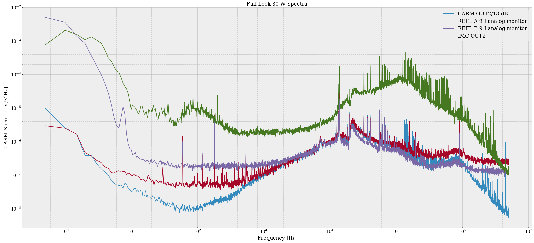
The (scaled to remove the SR560 gain) results of these measurements are shown in attachment one.  It appears that the worst circuit noise originates in the Sum Node.
The big hump in the dark orange spectrum is probably a random RF line wandering through DC during our measurement, it is not present in the other measurements at low frequency.

During these measurements with OUT2, we noticed an mysterious peak wandering around at 60-80 kHz.  Georgia was able to toggle the frequency of the line with the Sum Node B Input1 being turned on and off, even though IN2 on the CMB was NOT connected.

----------------------------------------------

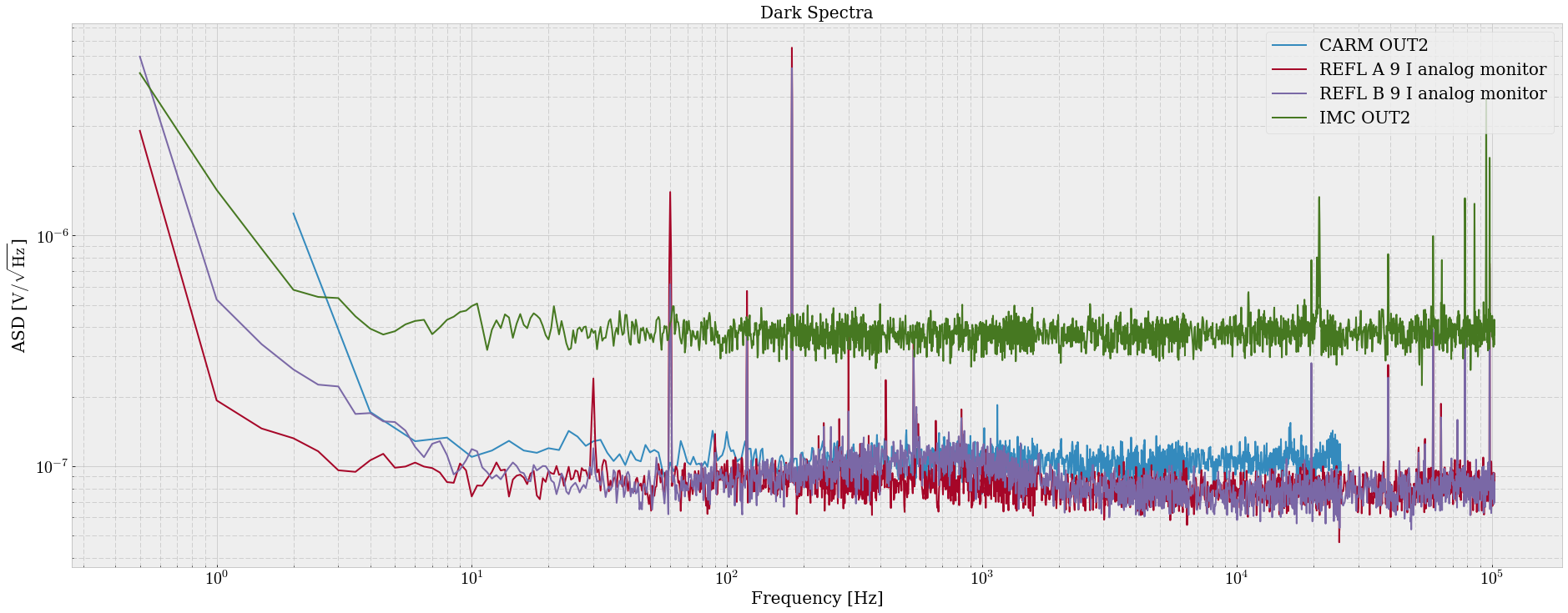
What does any of this mean for the CARM path?  The question came up when I measured REFL A 9 IMON and CARM OUT2 paths, and found that CARM OUT2 had lower noise than REFL A 9 IMON would have predicted. (red and blue in attachment two)
All it likely means is there is some additional sensing noise in the CARM path that we are just now understanding.
Also somehow the responses of REFL A and B analog monitors are vastly different to the same input.
Images attached to this report
Non-image files attached to this report

Comments related to this report
After some conversation with Daniel and more thinking, things seem bad for the REFL A demod board signal.

We put in -20 dBm (22.4 mV) into RF In, and got back 346.7 μV from REFL A 9 I and Q, and 120 mV from REFL B I and Q.
Barring some measurement mistake, the signal gain for the REFL A demod board is 0.0155.  For the REFL B demod board it is 5.36, much closer to spec.  The analog response ratio REFL B / REFL A ≈ 350.

This is strictly a signal attenuation, the dark and shot noise of the signal chain is the same for both PDs.

The LO monitors report the same input for both boxes.  Same for the RF monitors.

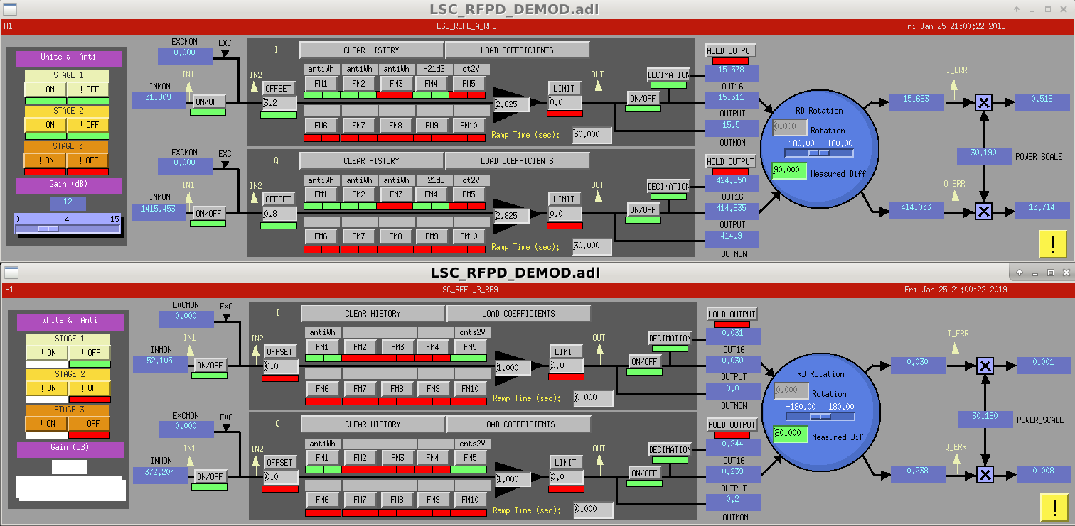
The digital readbacks of H1:LSC-REFL_A_RF9_I_ERR and H1:LSC-REFL_B_RF9_I_ERR are also consistent with low REFL A signal response.  I reported 0.438 counts peak response in REFL A, and 0.117 counts for REFL B, but when looking at the calibrations we see that REFL A FM5 [ct2V] is not applied, while it is for REFL B.  Assuming whitening is accounted for correctly, this is about a factor of 2^14/10 = 1638.4 cts/V difference, meaning the true REFL B / REFL A digital readback ratio is around 440.

The demod circuit is relatively simple: DCC D0902745.  If both analog and digital readbacks yield a low signal response the error in the board comes before the differential amplifier.  We also see the reduced signal response in both I and Q channels for REFL A, indicating the error is probably before the PE4-140s.  And if the RF and LO monitors report the same inputs for both boxes, the error is after the RF directional couplers.  This means the most likely candidate for the signal attenuation is the transformers (TC4-1Ts), or somehow one of the directional couplers is not supplying what it claims to supply.
Images attached to this comment

Went out there to repeat the demod board ratio measurement for REFL A because if any of the above were actually true, locking would be impossible, and our dark/shot noise measurements would have to be different between REFL A and B.

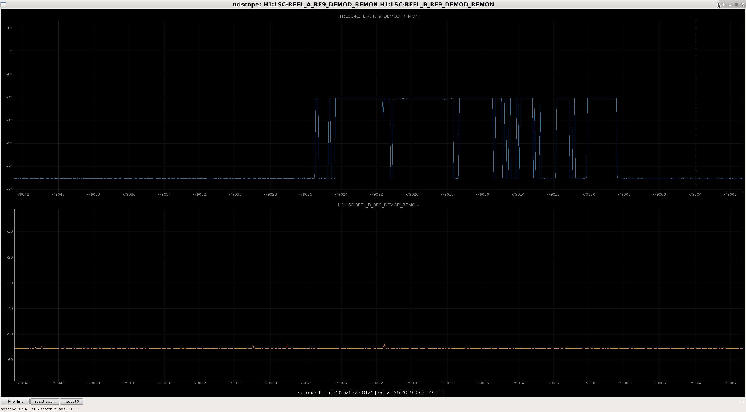
Turns out the Agilent RF source was not making a great connection when plugged into RF In.  In attachment one, the blue RFMON shows the connection was spontaneously dropping while the measurement was happening.  The cable must have been broken, since the measurement was repeatable.

This time I used a Marconi with 9.101 MHz and -20 dBm and exchanged the cable, and got a reasonable result:

Channel                                Response
-----------------------------------------------
REFL A 9 I analog monitor           117.6 mVrms
REFL A 9 Q analog monitor           118.2 mVrms
H1:LSC-REFL_A_RF9_I_ERR              48.4 cts

REFL B 9 I analog monitor           117.6 mVrms
REFL B 9 Q analog monitor           118.3 mVrms
H1:LSC-REFL_B_RF9_I_ERR               0.115 cts


The demod gain for both boards is 5.25.
Images attached to this comment