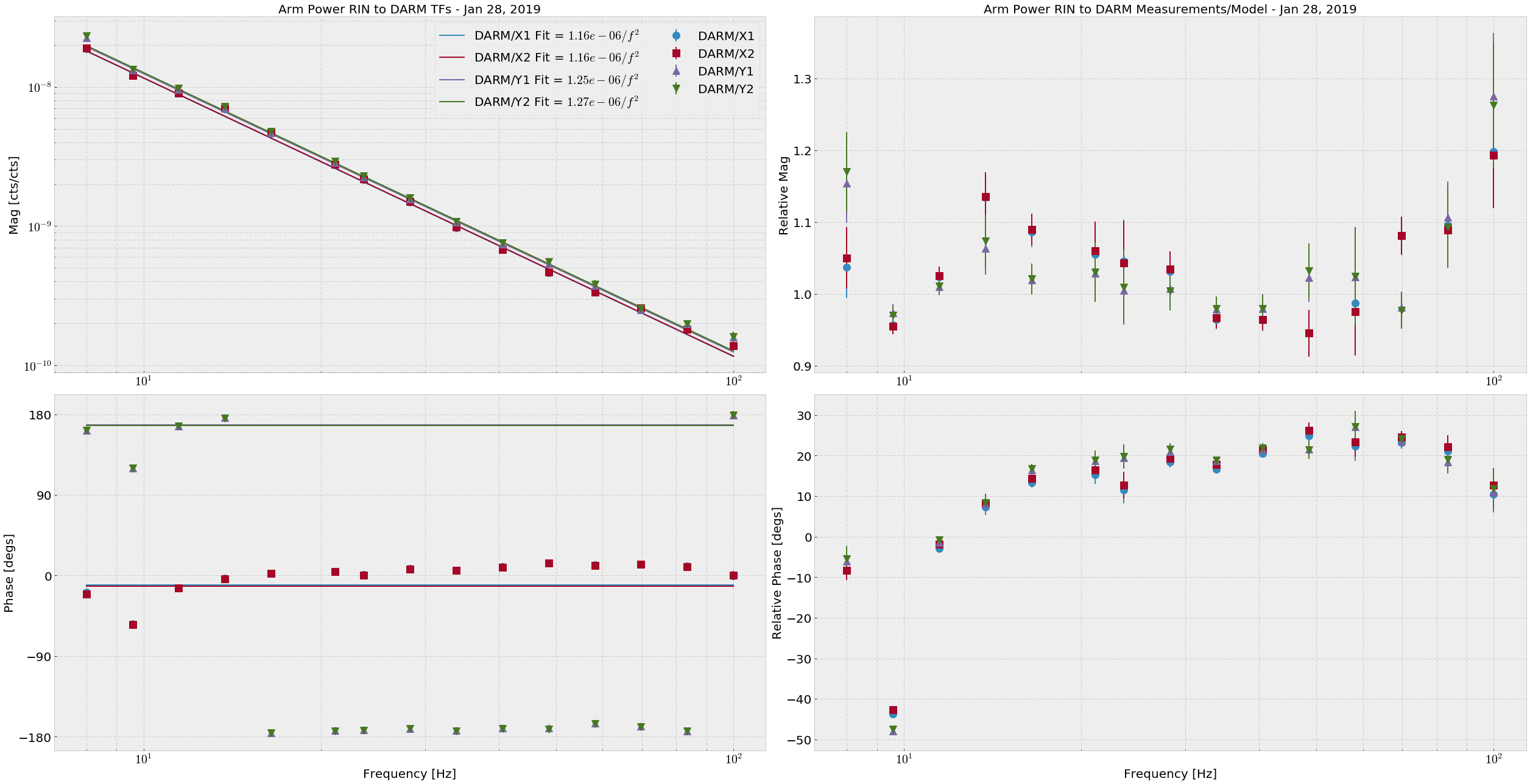
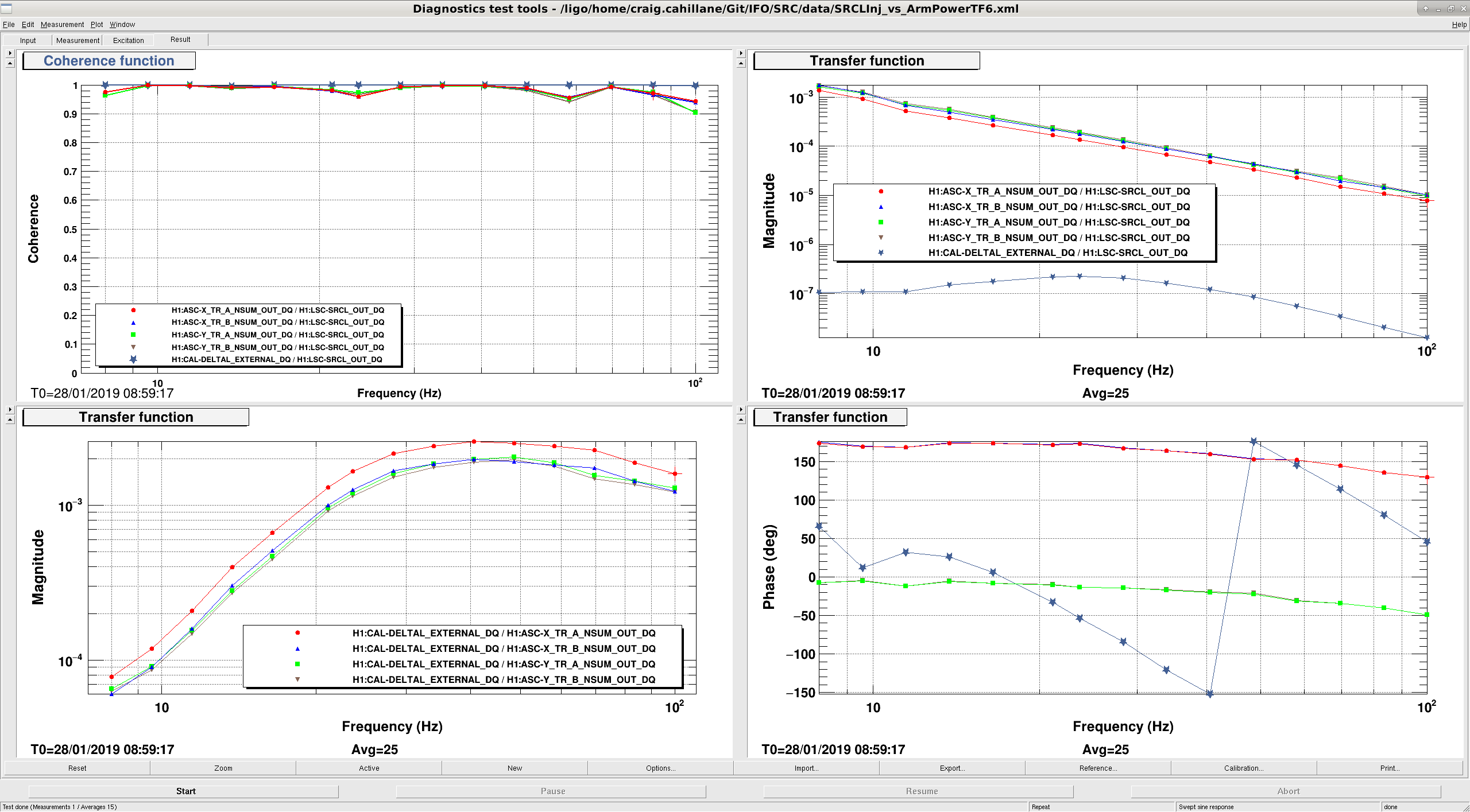
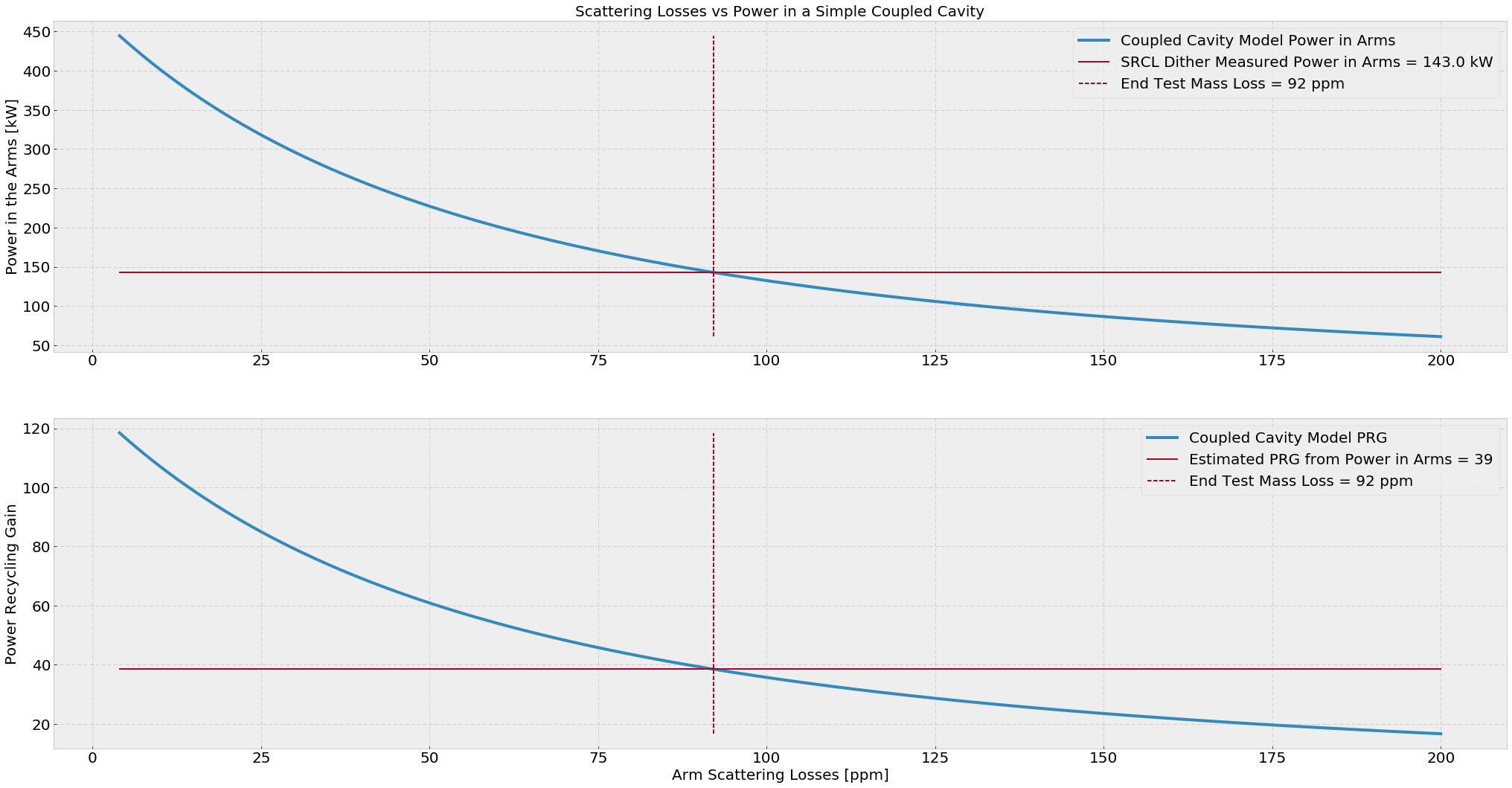
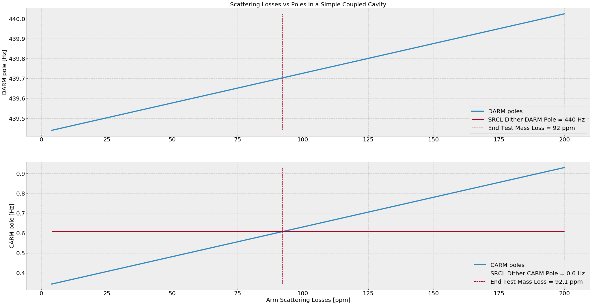
On January 8th I tried to measure the average arm power by dithering SRCL. Last night I did it again, this time with better TFs taken simultaneously. Average Arm Power = 143.0 +- 5.8 kW This time I directly fit each of the four Arm Trans QPD RINs (H1:ASC-{X,Y}_TR_{A,B}_NSUM_OUT_DQ) to DARM (H1:CAL-DELTAL_EXTERNAL_DQ), then fit a 1/f2 (attachment one). The DARM calibration used was the stop gap made by Keita. The average powers for the RIN calculation are as follows, and are good to +- 300 cts:Arm Trans QPD counts XA 145658 XB 191409 YA 207723 YB 221769This time the math is simpler:P_arm = DARM/ArmTransRIN Fit × π2 × m × cIf we look at the different in the arm trans RIN response between the arms, and say that the RIN we see is entirely due to radiation pressure in the arms, we get(DARM/Y)/(DARM/X) =,X/Y= 1.08meaning there may be 8% more light in the X arm than the Y arm. EDIT: It is actually the Y arm with 8% more light than the X arm. If we calculate the simple power recycling coupled cavity, I find that the estimated average ETM scatter losses are around 92 ppm and the estimated PRG here is 39. (attachment three) The measured value of PRG at the time of the measurement is 41.8, and the true input power was 26.5 W (requested was 30W). If we take these numbers to be true, then our arm gain according to the SRCL dither is 258.
Some simulation work related to this measurement.
From galaxy, I find that LHO's ITMX (ITM07) has a reflectivity of R_ITMX = 1.50%, while LHO's ITMY (ITM11) has a reflectivity of 1.42%. So there's quite an imbalance there.
I set up a simple simulation, using only the TEM00 mode, so without including any mismatch. Each arm has about 92 ppm of total round trip losses, following Craig's estimate. The first plot below shows some powers as a function of the two ITM reflectivities.
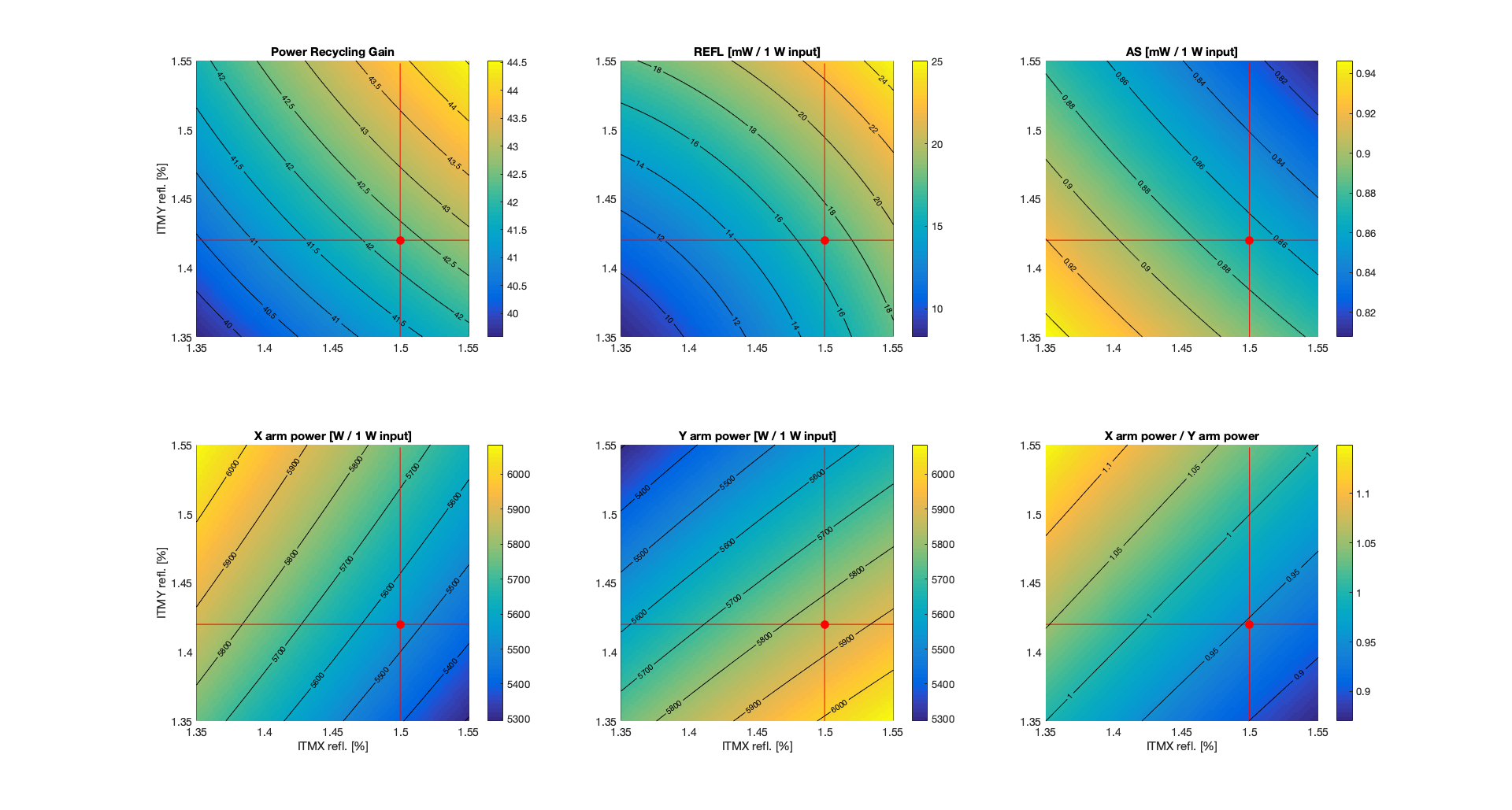
The red dot represent the nominal condition, which gives, for 1 W input power
PRG = 42.3
REFL = 17 mW (carrier only, TEM00, perfect matching)
AS = 0.9 mW (carrier only, TEM00m, perfect matching, nominal DARM offset of 1.2e-11 m
XARM = 5536 W
YARM = 5848 W
X/Y = 0.946 [more power in Y arm than X arm]
So there is more power in the Y arm than in the X arm, as one would expect since ITMY has higher reflectivity, so that the Y arm has higher finesse.
I also tried to reproduce more closely Craig's SRCL dither measurement. So in simulation, I computed the transfer function from SRCL motion to the RIN as measured in transmission of both arms. The plot below shows the simulated transfer functions RIN_ARM / SRCL for X and Y:
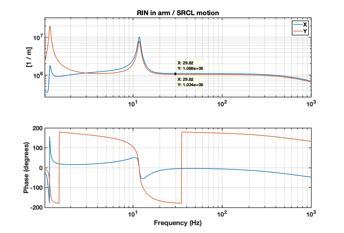
The numerical values are
RIN_X / SRCL_z = 1.088e6 /m
RIN_Y / SRCL_z = 1.034e6 /m
so (RIN_X / SRCL_z ) / (RIN_Y / SRCL_z) = 1.052. This is the ratio of powers, since the simulated transfer functions from SRCL to powers are equal for both X and Y, so the transfer functions to RIN are scaled by the inverse of the power.
Craig's measurement is actually the transfer function DARM / RIN while injecting on SRCL. In simulation, I used the AS port power as a proxy for DARM and computed the transfer functions TF(AS_DC / SRCL) and TF(RIN / SRCL). Then the equivalent of Craig's DARM / X and DARM / Y should be, at 30 Hz,
TF(AS_DC / SRCL) / TF(RIN_X / SRCL) = 98.4 W
TF(AS_DC / SRCL) / TF(RIN_Y / SRCL) = 103.6 W
and the frequency dependency is shown in the plot below (1/f^2 as expected).
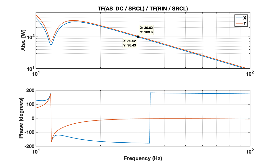
So the equivalent of Craig's ratio (DARM / Y) / (DARM / X) should be
[ TF(AS_DC / SRCL) / TF(RIN_Y / SRCL) ] / [ TF(AS_DC / SRCL) / TF(RIN_X / SRCL) ] = 103.6 / 98.4 = 1.053
which is greater than one as in Craig's measurement, but corresponds to the ratio POWER_Y / POWER_X.
So the conclusion from my simulation is that the ITM different reflectivities gives a ratio of TF (as measured by Craig) greater than 1, which corresponds to higher power in the Y arm than in the X arm (the opposite of what Craig's concluded...)
I didn't know that the ITMs were not the same reflectivity.  This is absolutely mind-blowing information.
I reported higher arm power in the Y arm before, from the HEPI measurement.
The RIN/SRCL TF corresponds to Equation 12 here.  It is not dependent on the arm power at all, but rather the optical response γ of each arm to the SRCL dither.
Also, the DARM/RIN TF in Equations 20 and 21 also indicate that DARM/RIN = 4*Parm/(m c ω2), so I made a mistake last night.
Good that the measurement and the prediction agree that there is more power in Y than in X.
Now we have to figure out why the measurement gives 8% imbalance while from the ITM reflectivities we only get 5%.
Updated simulation:
- added higher order modes (n+m<=10), measured test mass radii of curvature
- locked DARM to have an AS power that corresponds to 20 mA at 26 W input power (1.25 mW on the OMC transmission for 1 W input)
No change in the conclusions. Same imbalance of the arm powers as before (about 5%)
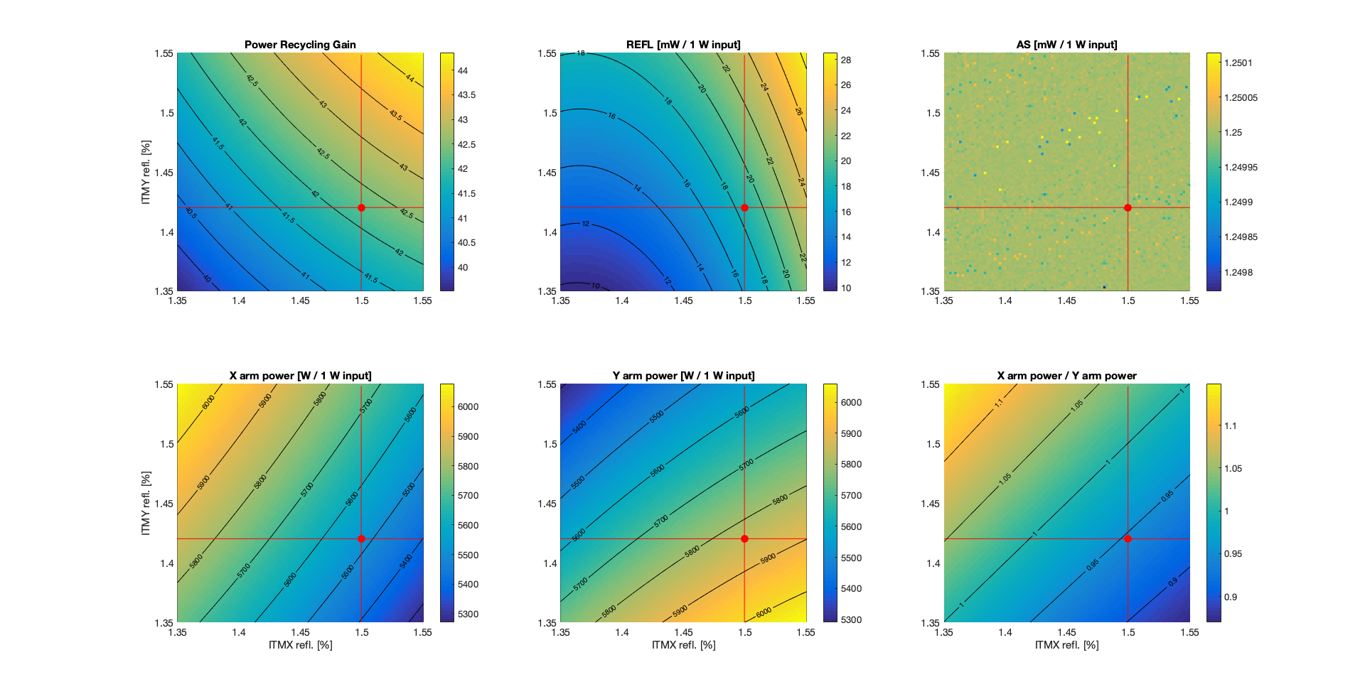
Adding the substrate lenses do not change significantly the power imbalance.
ITMX: static lens -310km, thermal lens +770km
ITMY: static lens +570kn, thermal lens +350km
Follow up to the discussion at today's commissioning call.
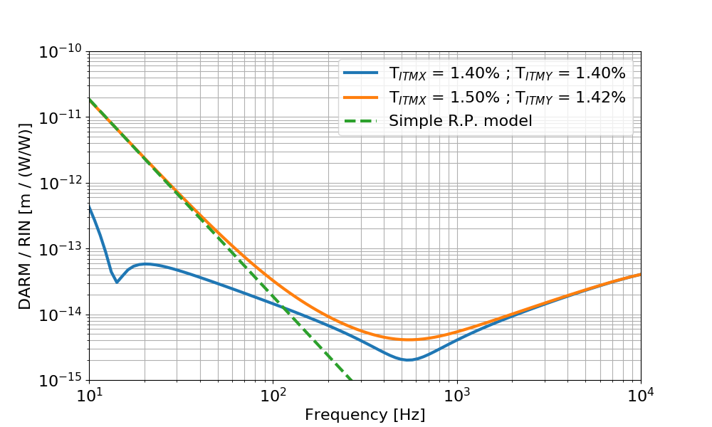
I computed the transfer function from laser relative intensity noise at the IFO input (called rin below) to DARM (calibrated in meters).
The input power is 26 W, and the round trip losses are adjusted to get a recycling gain of about 42. In the blue trace below, the two ITMs have the same reflectivity, equal to the nominal value of 1.4%. In the orange trace the two ITMs have different reflectivities, ITMX = 1.50% and ITMY = 1.42%, from the measured values from galaxy. This is the same configuration used in the other simulations, that gives a 5% power imbalance.
The dashed green curve is a simple radiation pressure model according to the equation below:
where RIN_arm / RIN_input is basically the double cavity pole (since input RIN is filtered by this transfer function. I used the simulated result), Delta P is the DC power difference in the arms ( Y - X = 7.7 kW) and m is the mirror mass. This matches quite well the low frequency simulation.
Using the simulated transfer function I can see what level of RIN at the IFO input would limit the sensitivity. It turns out that one needs a RIN of about 5e-6 (W/W)/rHz.
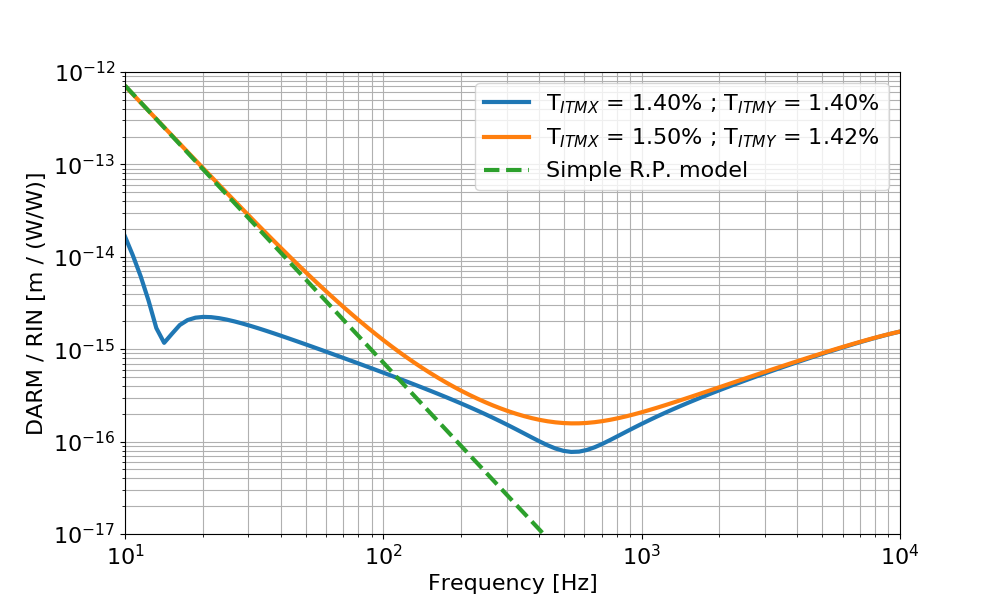
I found a mistake in my previous RIN simulation (many thanks to Matt Evans for spotting the inconsistency). Here's the correct results and plots.
Follow up to the discussion at today's commissioning call.
I computed the transfer function from laser relative intensity noise at the IFO input (called rin below) to DARM (calibrated in meters).
The input power is 26 W, and the round trip losses are adjusted to get a recycling gain of about 42. In the blue trace below, the two ITMs have the same reflectivity, equal to the nominal value of 1.4%. In the orange trace the two ITMs have different reflectivities, ITMX = 1.50% and ITMY = 1.42%, from the measured values from galaxy. This is the same configuration used in the other simulations, that gives a 5% power imbalance.
The dashed green curve is a simple radiation pressure model according to the equation below:
where RIN_arm / RIN_input is basically the double cavity pole 0.6Hz/fr (since input RIN is filtered by this transfer function), Delta P is the DC power difference in the arms ( Y - X = 7.7 kW) and m is the mirror mass. This matches quite well the low frequency simulation.
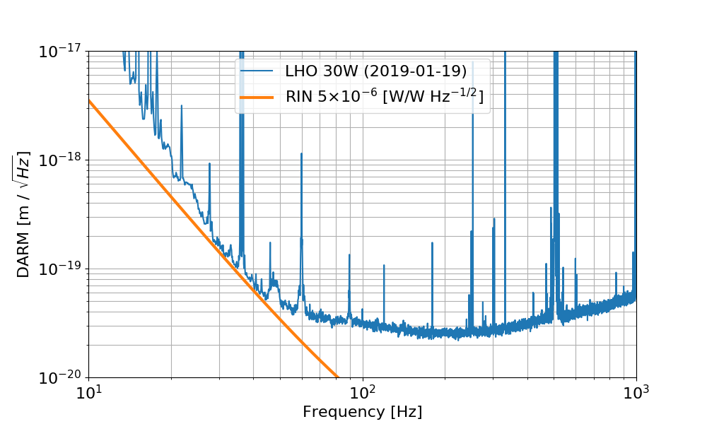
Using the simulated transfer function I can see what level of RIN at the IFO input would limit the sensitivity. It turns out that one needs a RIN of about 2e-7 (W/W)/rHz.

Doesn't this 2e-7 /rtHz RIN seem dangerously close to the measured value at 30Hz?
The intensity noise projection in the noise budget is made by injecting into the ISS second loop. It shows that the intensity noise is not close to DARM. 45828