jeffrey.kissel@LIGO.ORG - posted 13:29, Tuesday 28 September 2021 - last comment - 15:06, Tuesday 28 September 2021(60049)
H1 SUS OMC Damping Loops Improved: Above 10 Hz Sensor Noise Suppression Better by Factors of 10-20, Ringdown Times improved by Factors of 2
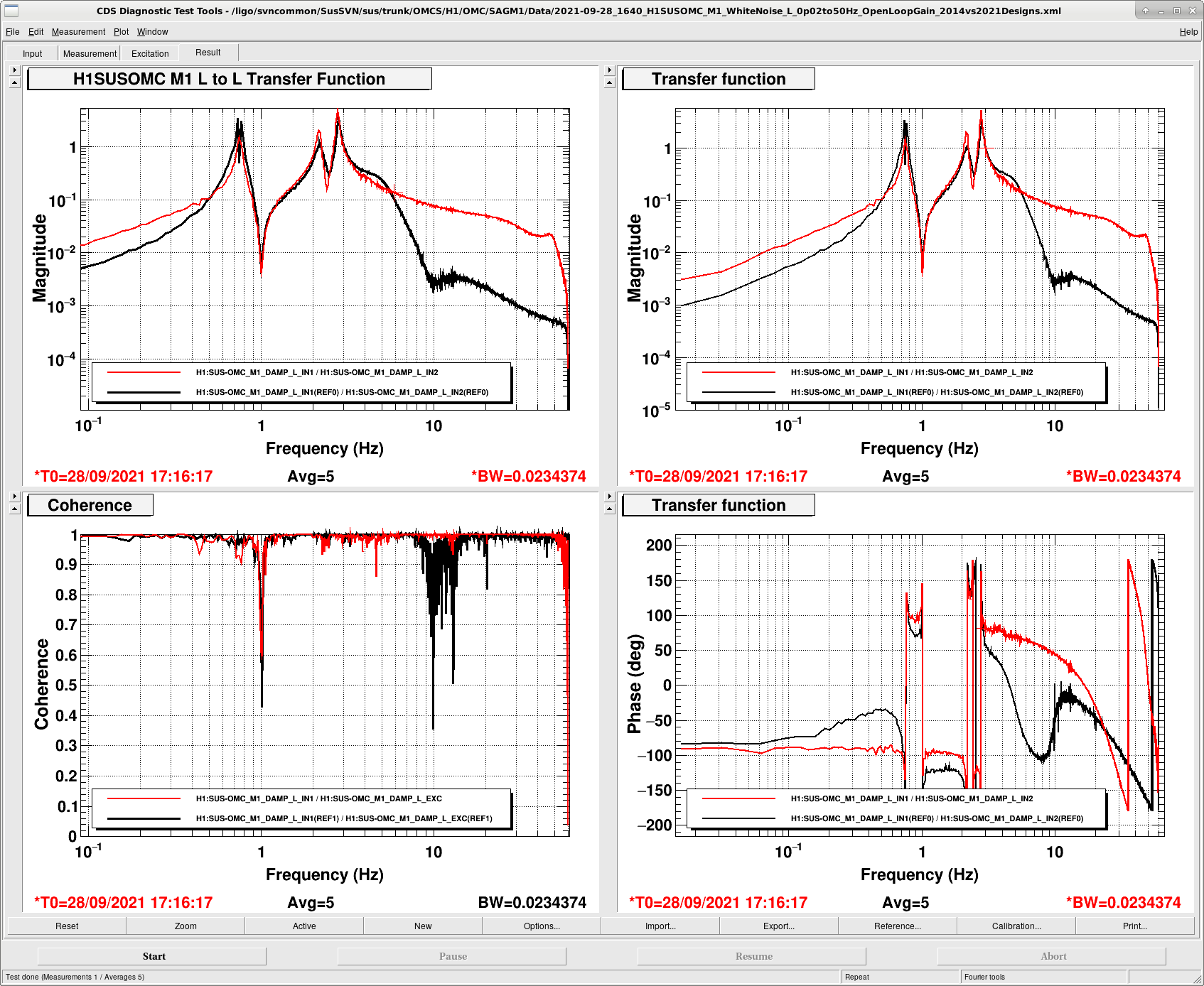
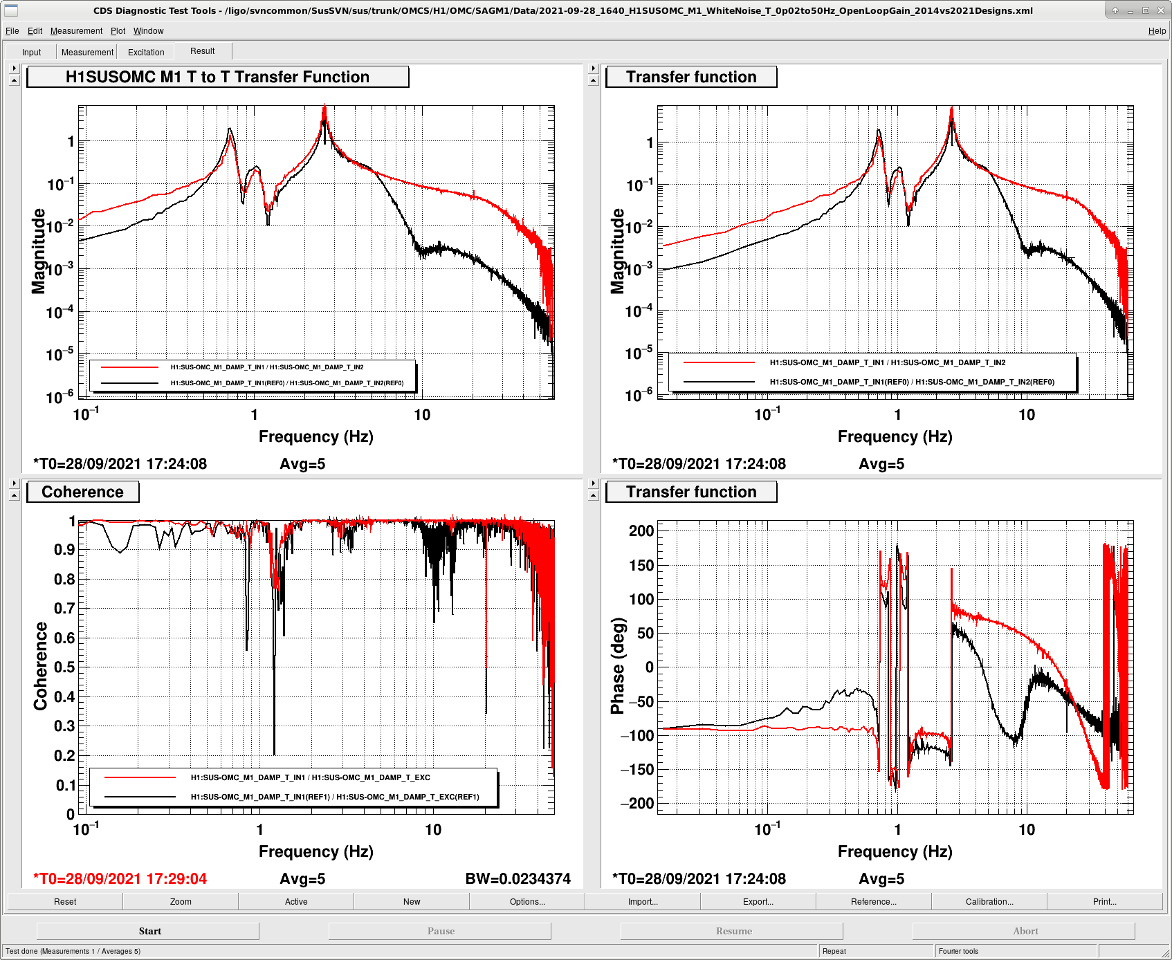
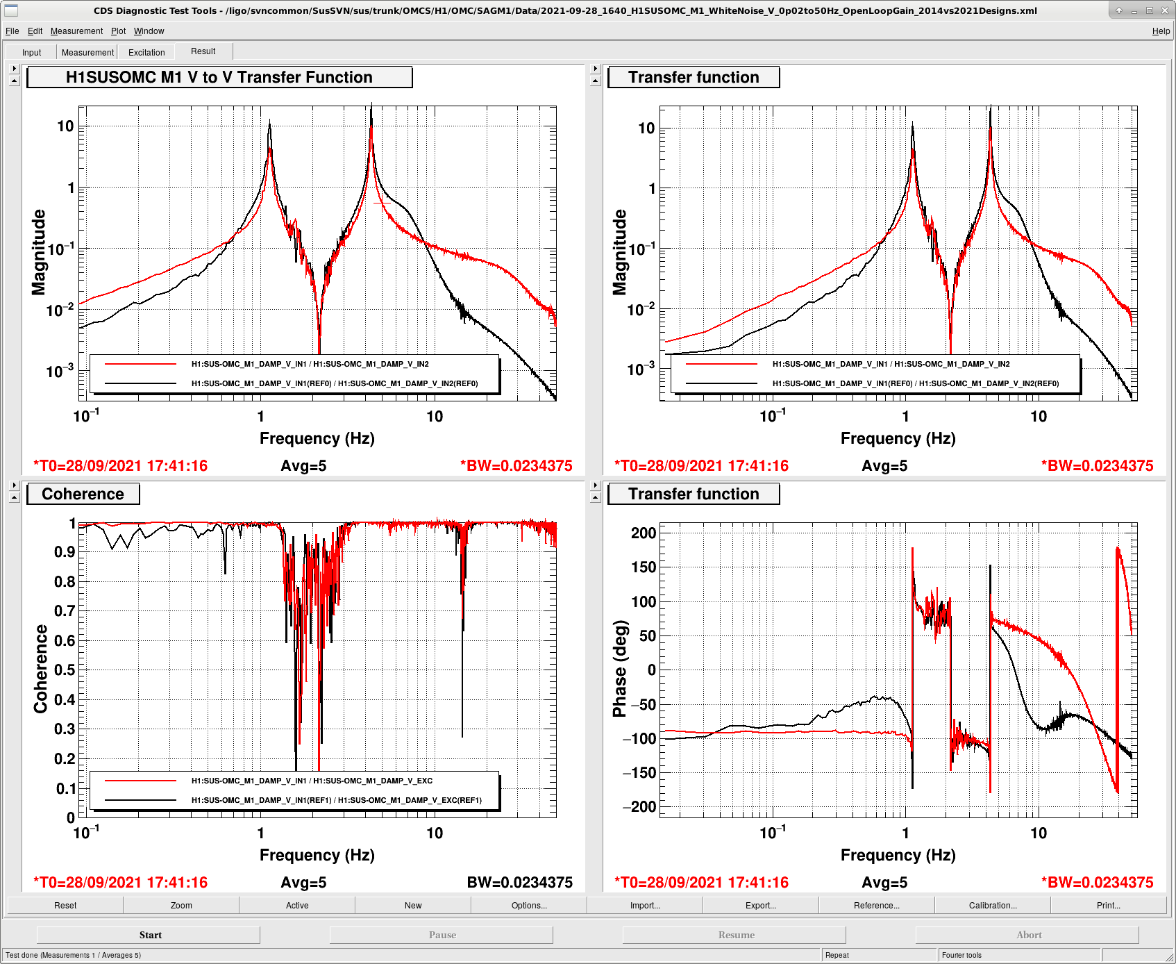
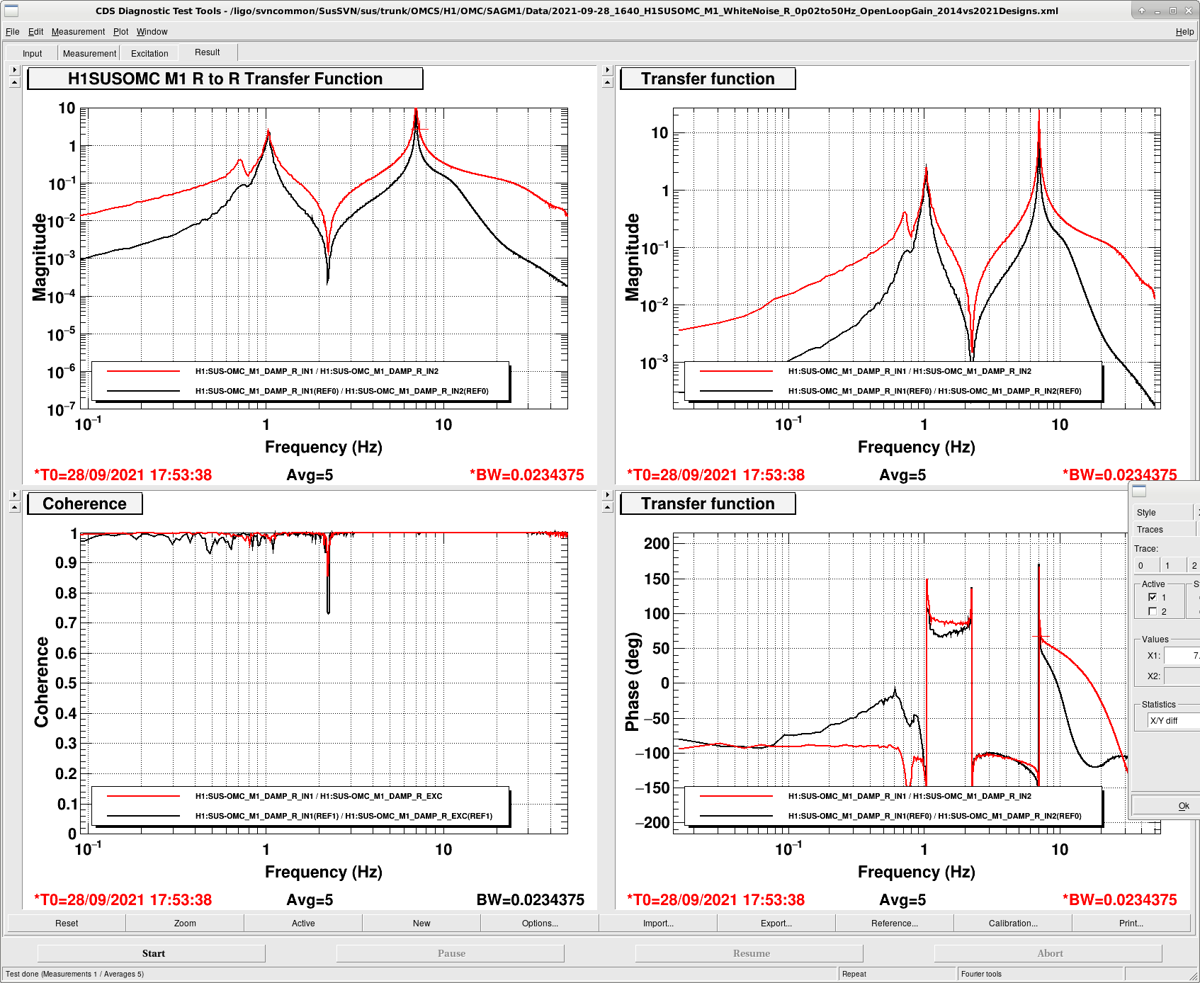
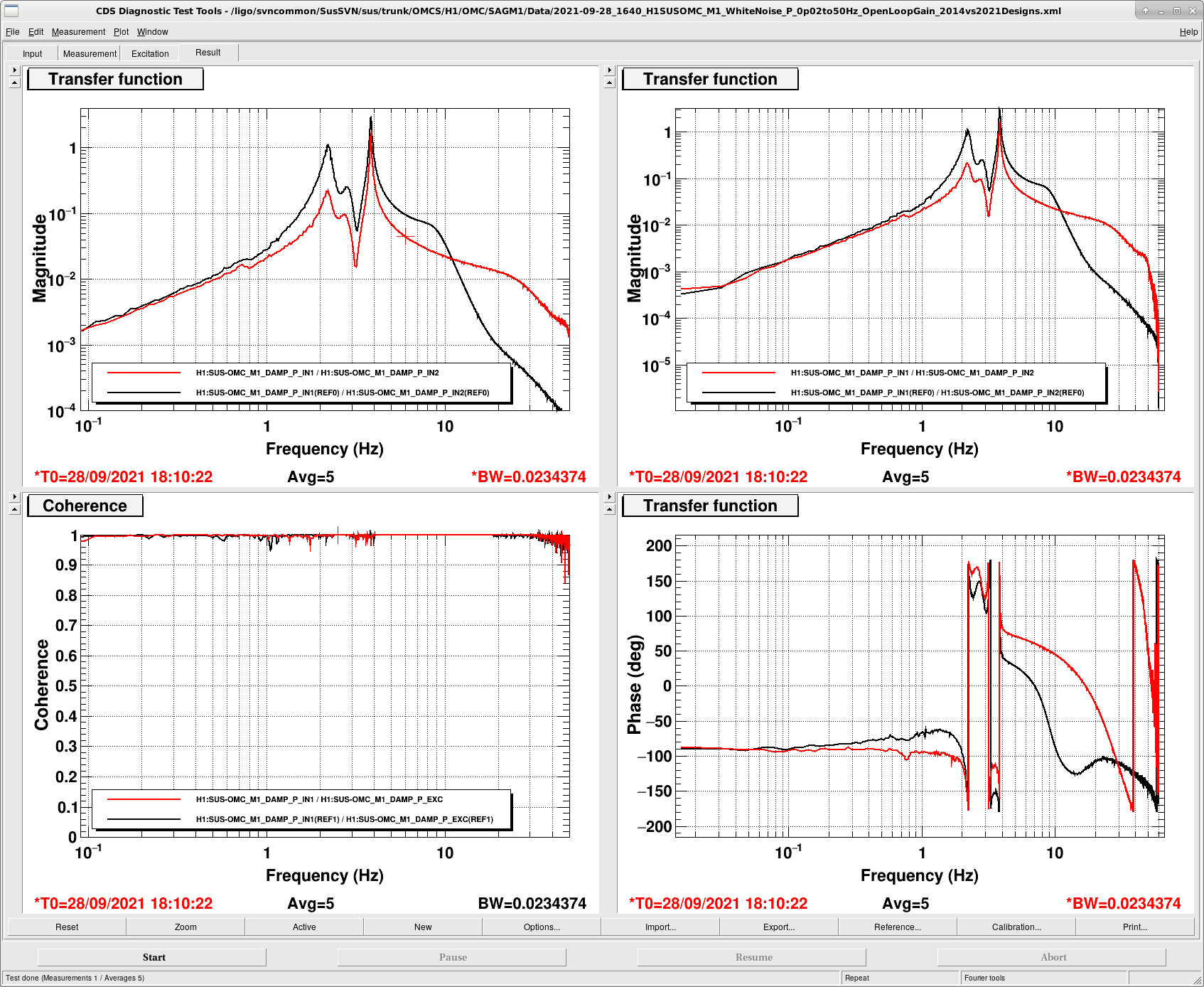
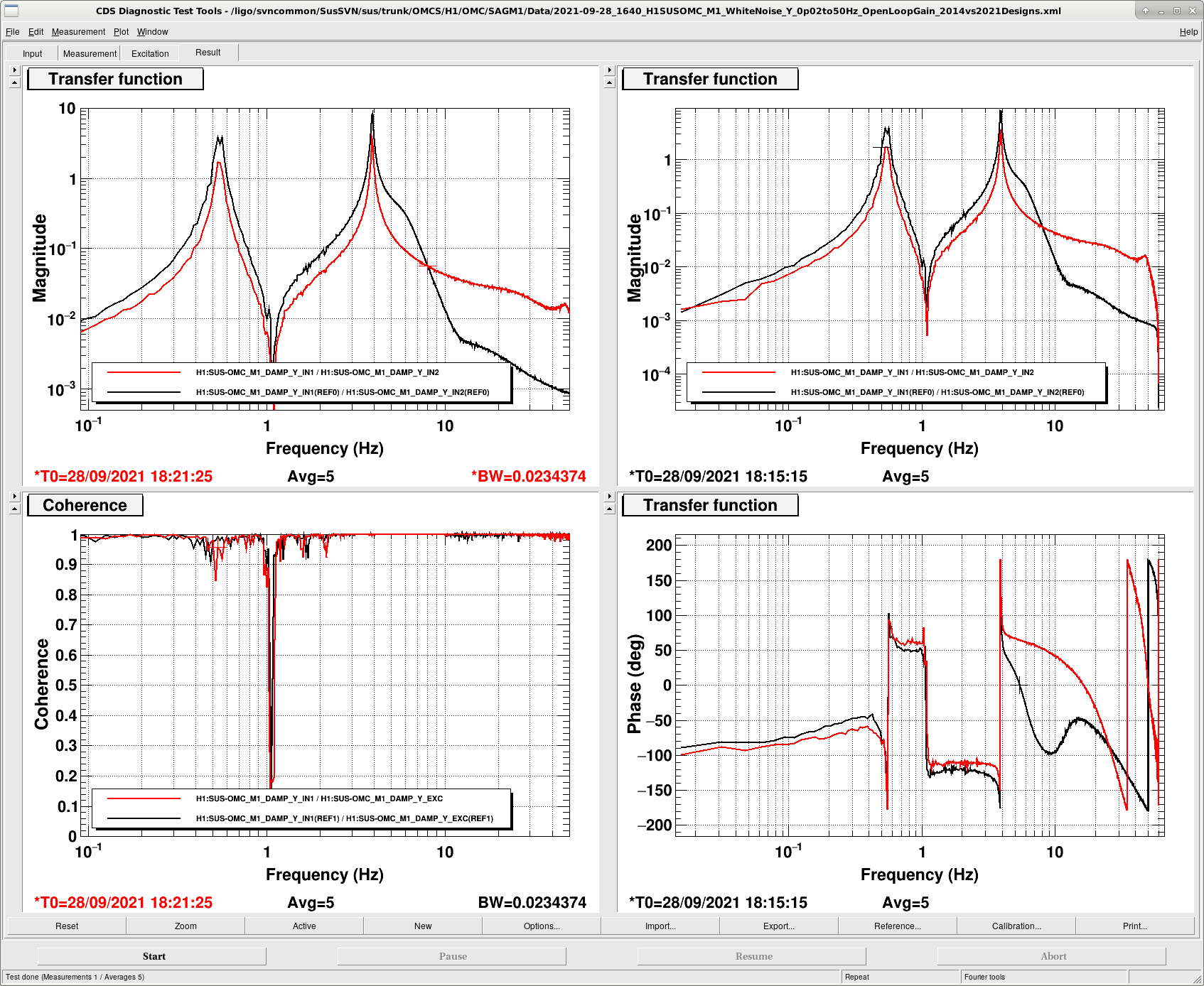
J. Kissel, V. Srivastava

After working with Varun to better understand the need for (finally) improving the OMC damping loops from the primitive 2014 design (see LHO aLOG 60027 and citations there in), I used the "Level 2" design infrastructure that I recently created for the OMCS (again, see LHO:60027) to improve the filters all around.

To re-iterate the motivation -- Georgia, Peter, and Varun have found that the OMC ASC loops -- causing "jitter" on the alignment in to the OMC cavity, which in turn creates (relative) intensity noise on transmission through the cavity on to the main, DARM, DC PDs -- are a source of noise that's quite close (within a factor of two) to the DARM sensitivity in O3 between 10 and 60 Hz (see LHO aLOG 59041). Further, they've shown that OMC ASC noise in this frequency region is dominated by P and Y angular jitter of the OMC and OM3, and OMCS and HTTS respectively -- more so by OM3. Finally, they've shown that the source of the angular jitter on both suspension types is poorly rolled off BOSEM sensor noise from primitive damping loop design (see LHO aLOG 59062 for OM3), and just below that is DAC noise transmitted through the actuator noise, for which we'll likely be changing the HAM-A driver (see G2102098).

Anyways -- this aLOG and subsequent comments is about the improvement to the damping loops of lesser of the two contributors, the OMC. I started there first since it was easier to build up the design infrastructure for it, (even though it's less of a noise limitation on the OMC ASC loops, simply because it's a double suspension with more passive isolation of its sensor and actuator noise), and also, I'll eventually be using the same design infrastructure to design HXDS damping loops.

The attached plots show the comparison between the *measured* open loop gain transfer functions (measured in-loop with all DOFs on to properly show the MIMO results) for before and after for all DOFs. One can see with this design, we get
                                     L             T            V            R         P            Y
LO Lowest Lower UGF [Hz]            0.70         0.68         1.00          0.99      2.18         0.49
HI Highest Upper UGF [Hz]           3.01         2.89         5.00          7.32      3.95         4.38
Phase Margin LO/HI [deg]         72.9/58.0    60.4/51.3    69.6/49.7    111/45.8    155/48.7    77.9/38.9
Gain Margin
   (1/abs(G) @ HI 0 [deg])          3.47         3.65         2.36         5.75      12.77         8.22
Factor of x Improvement
   1/e Ringdown time              x 1.9        x 0.8        x 1.3         x 0.7     x 1.1        x 2.1
   20 Hz Suppression              x22.9        x28.6        x12.0         x38.5     x13.8        x 9.1

I'll add comments and details about the design below.

These new damping loops are installed, running, functional, and their configuration has been saved into the SDF system.
The run with FM1, FM2, FM4, FM5, and FM10 on.
For future comparison of "old .vs new" filters, I've shoved all of the old filters and gains in to FM6, FM7, and FM8 (and, for YAW, also FM9).
Images attached to this report
Comments related to this report
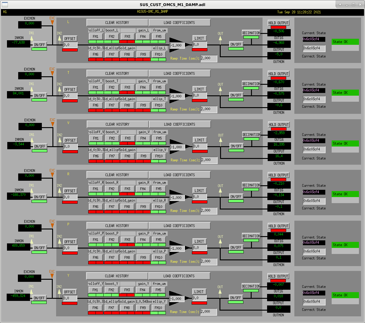
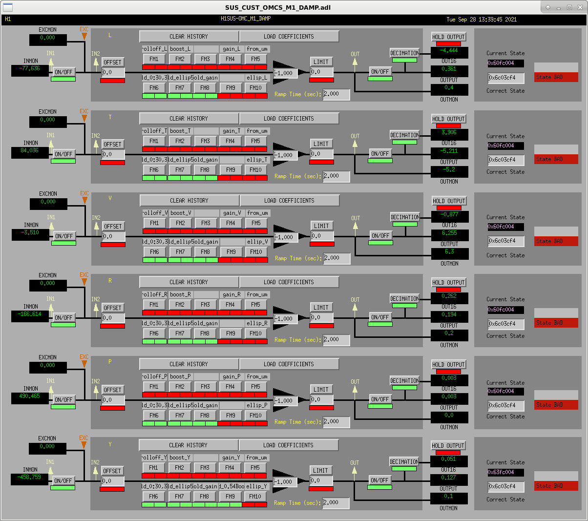
The MEDM configuration

2021-09-27_H1SUSOMC_M1_DAMP_Configuration_For_2021_Design.png : I show a screenshot of how the M1 DAMP filter banks configured with these new damping loops on.
All scalar gain that's tailored to each degree of freedom is hidden / hard-coded in the "gain_{DOF}" FM4 filter module, such that all DOFs should be run with an EPICs gain of -1.0.

2021-09-27_H1SUSOMC_M1_DAMP_Configuration_to_Reproduce_Old_Damping_Filters.png : I show a screenshot of how the M1 DAMP filter banks can be configured if one wants to reproduce the behavior of the old damping loops.
Images attached to this comment
The Filter Design

With the filter design script
    /ligo/svncommon/SusSVN/sus/trunk/OMCS/Common/FilterDesign/Scripts/
        design_damping_OMCS_20210924.m

and the exact same generic plotting functions discussed in LHO:60027, I created the first attached set plots, dampingfilters_OMCS_OMC_2021-09-24.pdf.

This walks through the same set of plots as I walked through in the 2014 design (and all "Level 2" designs).

Of course, with so many plots too look at, the second time through it's perhaps more easy on the brain to look at comparisons between the designs to see what's changed. I've made that set of plots in dampingfilters_comparison_2014-12-06_LHOvs2021-09-24_LowNoise.pdf with
    /ligo/svncommon/SusSVN/sus/trunk/OMCS/Common/FilterDesign/Scripts/
        compare_omcs_dampfilter_design.m
Here's, for example, where estimates, of improvements in ring-down times have come from.

Design philosophies:
    - For all these DOFs, I've strived to get as much 20-30 Hz sensor noise loop suppression (well, more like lack of re-injection) as I can -- but only to "a point." That "point" is where improving the loop would serve diminishing returns because in that frequency band, the estimated residual seismic noise (at these frequencies) and actuator noise does not change with damping loop design.
    - This is why you typically see the sensor noise re-injection prediction lying quite close too, if not just surpassing the predicted residual seismic noise.
    - For this reason, I use a low-Q elliptic filter, which may not have a lot of suppression at 50 Hz, but it's suppression just after the corner frequency is typically around 20 to 50, *only* that much -- unlike an infinite Q elliptic that one is limited to in a foton design -- and then rolls off softly after that once we gain the advantage of further passive isolation.
    - I make sure that at now where in the frequency band is the gain peaking (as measured by the magnitude of 1 / (1+G) ) more than a factor 2.
    - Because the lowest frequency mode has the largest seismic input motion, and thus dominating the displacement noise RMS, I focus as much gain as possible with a "resonant gain" "boost" filter at that "first" lowest frequency mode.
    - I take full advantage of the MIMO system for DOF pairs L / P and T / R. For these DOFs, because they are fundamentally cross-coupled, the lowest frequency two resonances represent mode shapes that contain both L and P, or T and R. Thus, one can apply a boost in one DOF, and it'll suppress the mode in the other DOF. In this way, I can save phase margin in the first lower unity gain frequency crossing. This manifest as me typically boosting the lowest of the modes in the translational DOFs (L and T), and the second lowest in the rotational DOFs (R and R, respectively).
    - Make sure that all modes are suppressed enough that the 1/e ringdown time is within 5-ish seconds, and not dominated by any higher frequency modes (which typically are harder to damp because one needs to roll-off the loop gain as fast as possible). The most challenging DOF for meeting this metric was Roll, given that it's highest resonance frequency is the highest at 7.01 Hz. As such, for this DOF, the ringdown time is actually a bit worse than it was before.

Almost all of these goals are met with a surprisingly simple few filters for each DOF:
    - FM1: "rolloff" =
        - a zero at 0 Hz, as per typical velocity damping,
        - a zero between 0.5 and 3 Hz, with an accompanying pole between 10 and 20 Hz to give some extra phase "lift" for the boost and elliptic filters to improve stability, and
        - a soft set of 2 real poles between 20 and 30 Hz to ensure *eventually* the sensor noise is well suppressed.
    - FM2: "boost" =
        - a "resonant gain" filter centered on the lowest frequency mode of the DOF (or if a cross-coupled DOF, then on the second lowest; see above)
    - FM4: "gain"
        - a scalar gain that sets the overall loop-gain. ***
    - FM5: "from_um"
        - a calibrating filter that returns the loop input to ADC counts, such that the filter can coupled to a dynamical model of the suspension in terms of (ADC ct) / (DAC ct). Or, read differently, it makes the units of the filter more physical, as in (DAC ct) / um, instead of (DAC ct) / (ADC ct).
    - FM10: "ellip"
        - a 3rd order, 1 dB ripple, low-Q (10 or less), elliptic filter, with 30 dB stop-band suppression whose corner frequency is pushed to be as low as possible, between 5 and 11 Hz.

Some particular notes:

. While the "from_um" has a standard dimensionful gain in units of [(ADC ct) / um] across all suspensions ever of
             % <---------------- Sensor Chain --------------->
             %     OSEM                     SatAmp
             %  Sensitivity                TransImp.    ADC
             % [uA / mm]  [mm / um] [A/uA]   [V/A]  [ADC ct/V]
    from_um = (76.29/0.7)*(1e3/1e6)*(1/1e6)*(240e3)*(2^16/40) = 42.855;
because all OSEMs have been normalized to have sensitivity of (76.29/0.7) [uA / mm], and have a transimpedance amplifier "gain" of 240e3 [Ohm], there does seem to be one flaw in my modeling scripts, because I aside from the "gain" which I predict I need in the model, I need an addition fudge factor gain of 50 for all DOFs. This is why -- if anyone *ever* digs this deep, which I doubt -- inside all of the gain filters, you'll see and extra "gain(50)" factor in addition to the gain that matches the design script,
    /ligo/svncommon/SusSVN/sus/trunk/OMCS/Common/FilterDesign/Scripts/
        design_damping_OMCS_20210924.m


. The low Q elliptic filters are designed by a sweet function made by Brian Lantz,
    /ligo/svncommon/SeiSVN/seismic/Common/MatlabTools/
        myellip_z.m
which I hope one day will be incorporated into foton (see DTT issue tracker 252).

. The only other potential gotcha is the actuator noise estimate.  I mention this in LHO aLOG 60027 as well, where I first introduce how I've fudged the DAC noise propagation through the actuator chain by scaling the Triple TOP coild drier trans conducatance by the ratio output impedance (well, the ratio of 1 / (2*Zout + Zcoil)) between the OMC TOP driver and the Triple TOP driver. Eventually I may update this noise estimate, but I'm reasonably confident that the passive isolation from the double suspension is plenty enough such that residual seismic noise is always above actuator noise at 10 Hz. This all being said, for almost all DOFS, above 10 Hz, the residual sensor noise reinjection is still higher that residual seismic noise, and thus actuator noise is third on the list of noise sources and less important to get right (if it is indeed that low).
Non-image files attached to this comment

The open loop gain transfer function measurement templates

Since it's so rare that we have so much time with suspensions, we rarely, if ever, I have time to properly characterize the open loop gain transfer functions for suspensions. We *should* -- especially because most suspensions have middle-frequency resonances that are quite different than there model (in this case the second pitch mode frequency of the OMCS) -- but we don't. This is because it take a lot to be aware of -- namely that as you're changing filter design, you have to change the excitation in a frequency dependent way to essentially match / invert the damping loop.

Now, because, after install, I wasn't getting *nearly* the amount of damping I'd designed, I did a quick check of a few DOFs to see what was wrong -- starting from the excitation that we use for the *much* more standard "top to top" health check transfer functions, which either measure only P, or (if the damping loops are closed) P / (1+G). Once I found that those few DOFs we off by a gain of *about* 50 (not identically 50 for all DOFs, sone were 45, some were 60) I wanted to see if I could get away with using 50 for all DOFs, and claim that there's some calibration factor wrong in the model. (And yes, I realized that 50 is quite close to 42.855, but if *that's* the missing gain in my model, then I'd be applying *two* factors of "from_um" in foton, which doesn't make sense to me).

Anyways -- we now have nice, beautifully crafted templates for all DOFs for the OMCS. These live here:
    /ligo/svncommon/SusSVN/sus/trunk/OMCS/H1/OMC/SAGM1/Data/
        2021-09-28_1640_H1SUSOMC_M1_WhiteNoise_L_0p02to50Hz_OpenLoopGain_2014vs2021Designs.xml
        2021-09-28_1640_H1SUSOMC_M1_WhiteNoise_P_0p02to50Hz_OpenLoopGain_2014vs2021Designs.xml
        2021-09-28_1640_H1SUSOMC_M1_WhiteNoise_R_0p02to50Hz_OpenLoopGain_2014vs2021Designs.xml
        2021-09-28_1640_H1SUSOMC_M1_WhiteNoise_T_0p02to50Hz_OpenLoopGain_2014vs2021Designs.xml
        2021-09-28_1640_H1SUSOMC_M1_WhiteNoise_V_0p02to50Hz_OpenLoopGain_2014vs2021Designs.xml
        2021-09-28_1640_H1SUSOMC_M1_WhiteNoise_Y_0p02to50Hz_OpenLoopGain_2014vs2021Designs.xml

Note, these transfer functions excitations were designed with the top mass M1 coil driver in State 1 (with the analog low-pass filter OFF; *not* in the nominal configuration of State 2, low pass off). Also, again, because the excitation frequency content much match the damping filters through which they're driving, I have two version of the excitations in the first two of four excitation parameter defining blocks of the template. The first is tuned for the old 2014 design, and the second is tuned for the new 2021 design. Just uncheck one, and check the other, making sure the damping loops are in the right corresponding configuration as shown above in LHO aLOG 60051.

Also, the excitation amplitude envelope frequency dependence isn't *that* different between the two, and I just started from the also already tuned standard health-check frequency response:
    - a low frequency boost, four poles at 0.1 Hz paired with four zeros at 1.0, with a normalizing at high frequency gain of 10000
    - a couple of resonant gain boost filters centered around the first few resonances to get some extra drive coherence
    - the standard 4th order, 1dB ripple, 40 dB stop-band suppression, infinite Q elliptic filter with corner frequency at 50 Hz to filter out any bad joo joo from excitation amplitude above where you're measuring, and
    - >> the only major difference << depending on whether it's the new or old design, I installed a high-frequency boost of two zeros at 5 Hz, paired with two poles at 50 Hz.
    - >> the minor difference << a differing over all gain between the two filters, usually be only a factor of 2 or so; roughly tuned such that most of the DAC range is used.

Enjoy!