Betsy, Kissel, Rahul
Yesterday afternoon (while doing the alignment work with Jason; adjusting pitch, height and yaw - see alog 60517) we took the first full set (i.e. all 6Dof) of transfer function measurements on FC1, connected to HAM 7 FC1 electronics chain and optic instead of metal bottom mass. See LHO alog 57873 for all metal FC1 TF results (connected to PR2 electronics chain near HAM3 and metal bottom mass) - it looked all healthy in Feb 2021. Also see alogs by Nidhi and Kissel, when they started working on taking the TF on FC1 with the new electronics chain, few weeks ago - 60171, 60459.
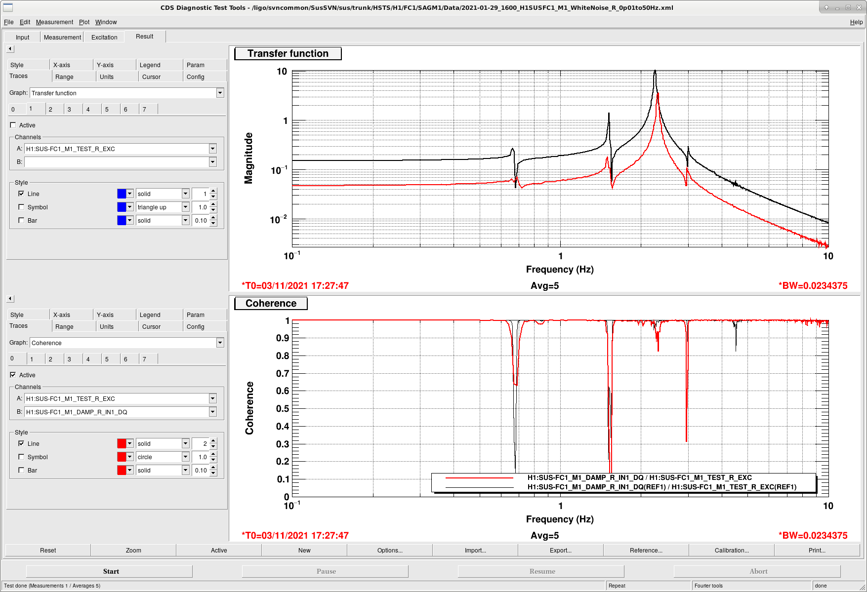
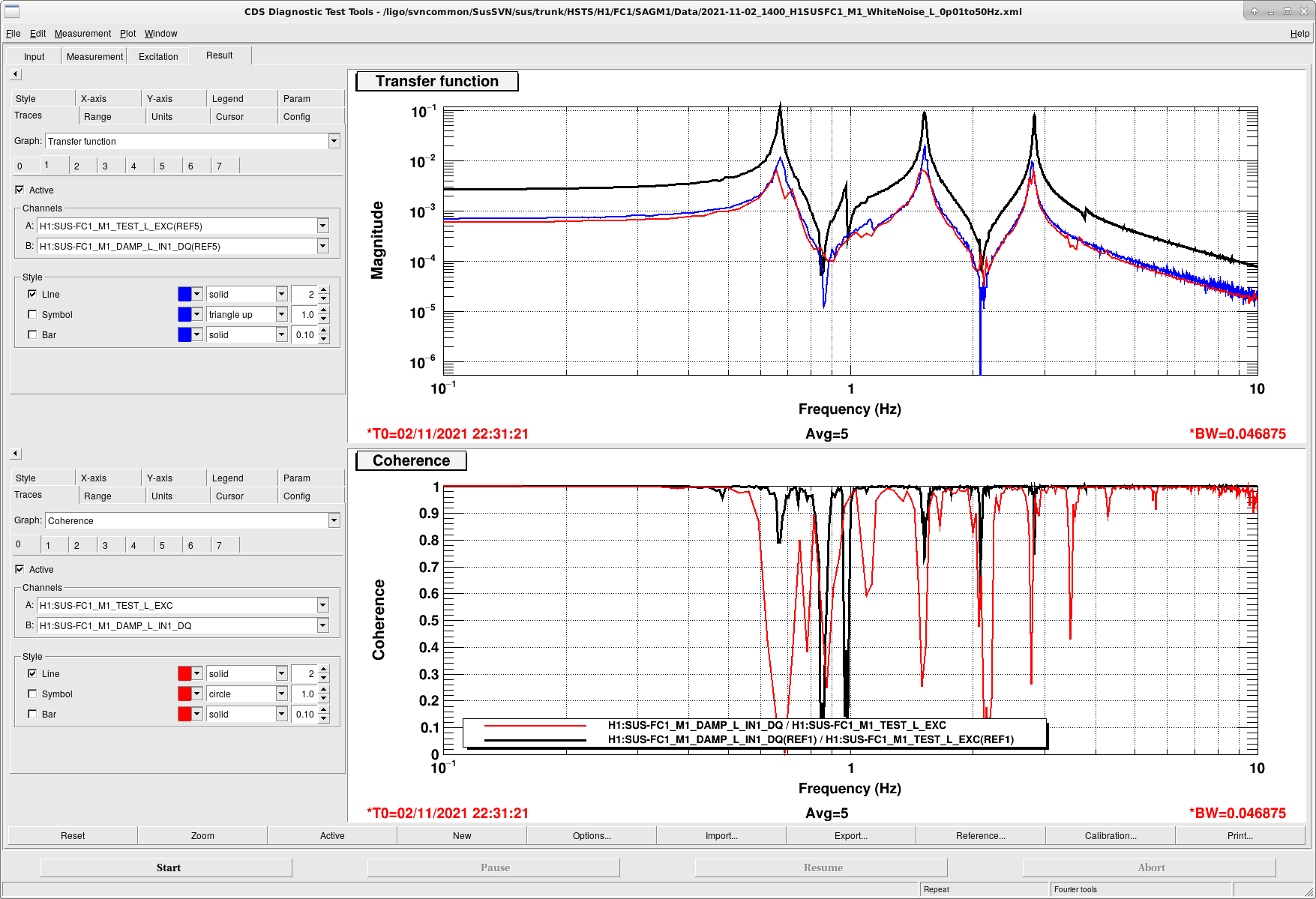
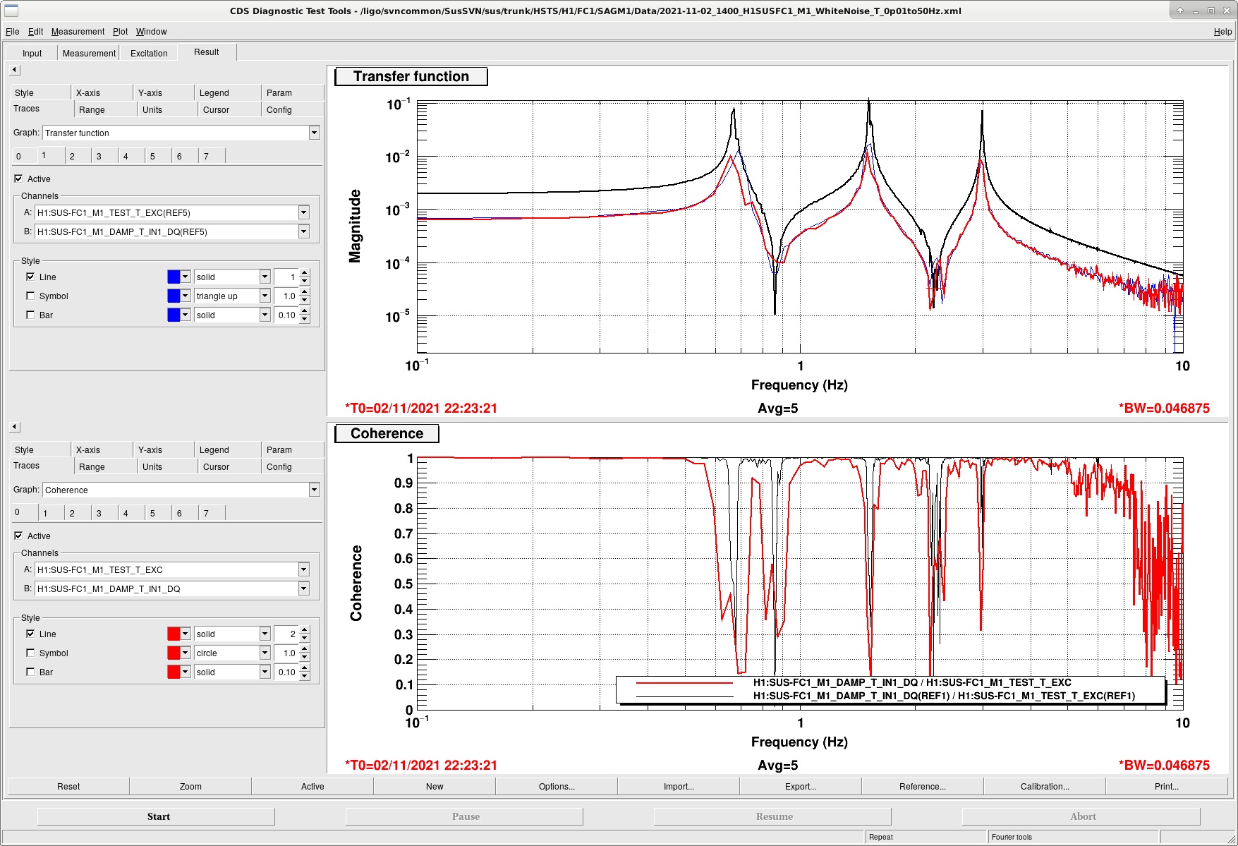
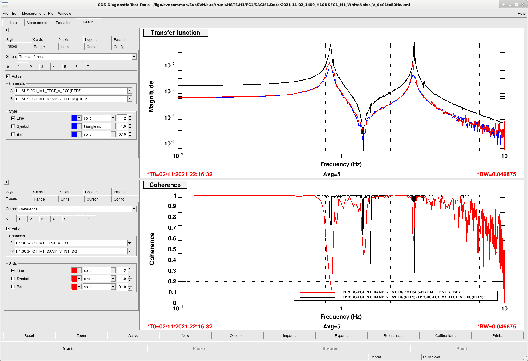
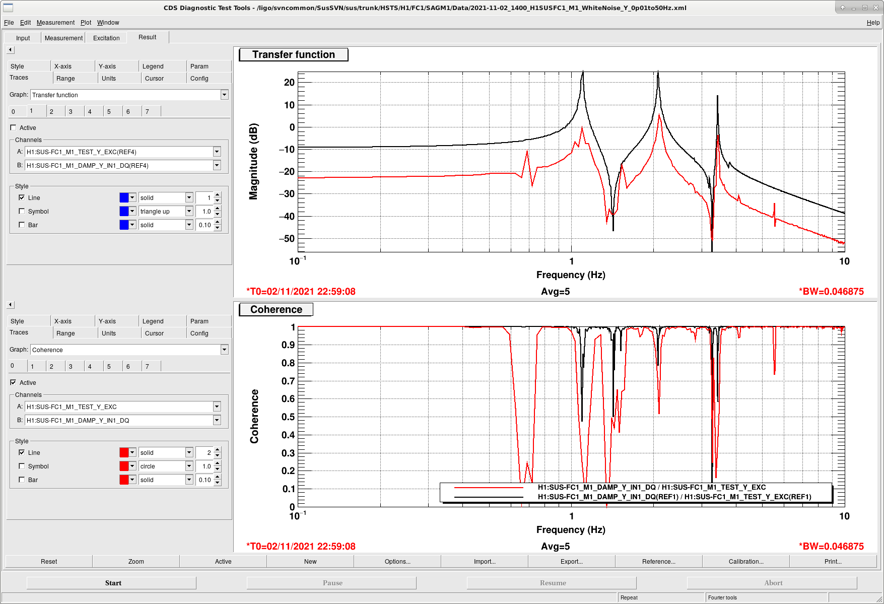
Attached below are the latest results for all 6Dof. The legend in red is our current measurements, black is for reference (from HSTS PR2), blue is for FC1 connected PR2 electronic chain). These measurements are coarse (BW 0.02 Hz) for quick results, hence the plots won't look smooth as we quickly wanted to check if all the peaks are there and there is no rubbing. Everything looks fine except the Pitch DoF where we are missing a peak at 3.3125 Hz. We get a peak at 3.60 Hz, but there should be 2 peaks in that region (as seen in the reference line in blue). Jeff Kissel suggested to double check the IM, if something it holding it up. Betsy and I checked all the EQ stops, wires, OSEM flags etc and everything looks free and the suspension is freely floating. At this point we are unable to diagnose the issue (could be differential pitch between BM and IM - although past experience doesn't suggest so?), however we will revisit this issue very soon and report back over here. Kissel has suggested to center M2 and M3 stage OSEMS, take another set of TF, make the plots in Matlab and then compare all the different DoF.
The .xml files are stored at the following location,
cd /ligo/svncommon/SusSVN/sus/trunk/HSTS/H1/FC1/SAGM1/Data/
2021-11-02_1400_H1SUSFC1_M1_WhiteNoise_L_0p01to50Hz.xml
2021-11-02_1400_H1SUSFC1_M1_WhiteNoise_P_0p01to50Hz.xml
2021-11-02_1400_H1SUSFC1_M1_WhiteNoise_R_0p01to50Hz.xml
2021-11-02_1400_H1SUSFC1_M1_WhiteNoise_T_0p01to50Hz.xml
2021-11-02_1400_H1SUSFC1_M1_WhiteNoise_V_0p01to50Hz.xml
2021-11-02_1400_H1SUSFC1_M1_WhiteNoise_Y_0p01to50Hz.xml
2021-11-02_1500_H1SUSFC1_M1_WhiteNoise_P_0p01to50Hz.xml
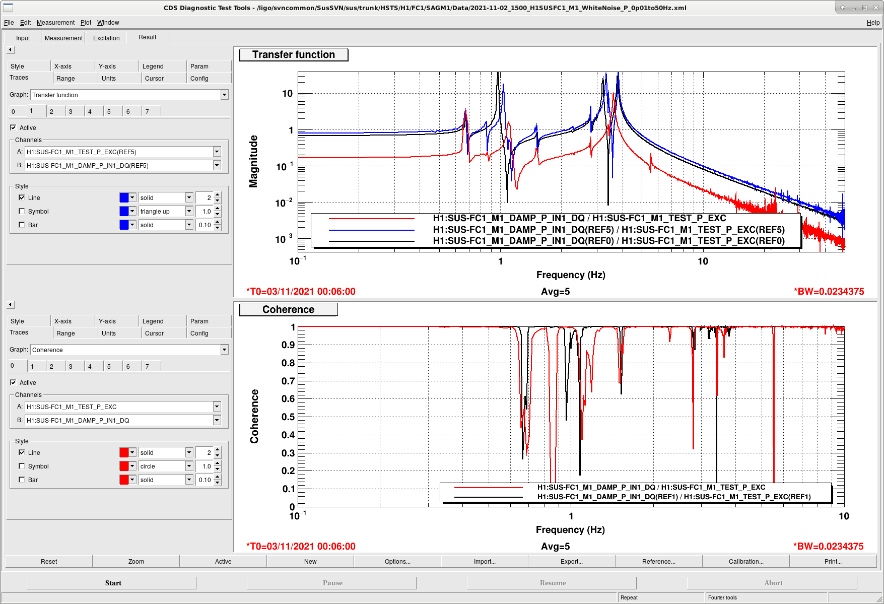
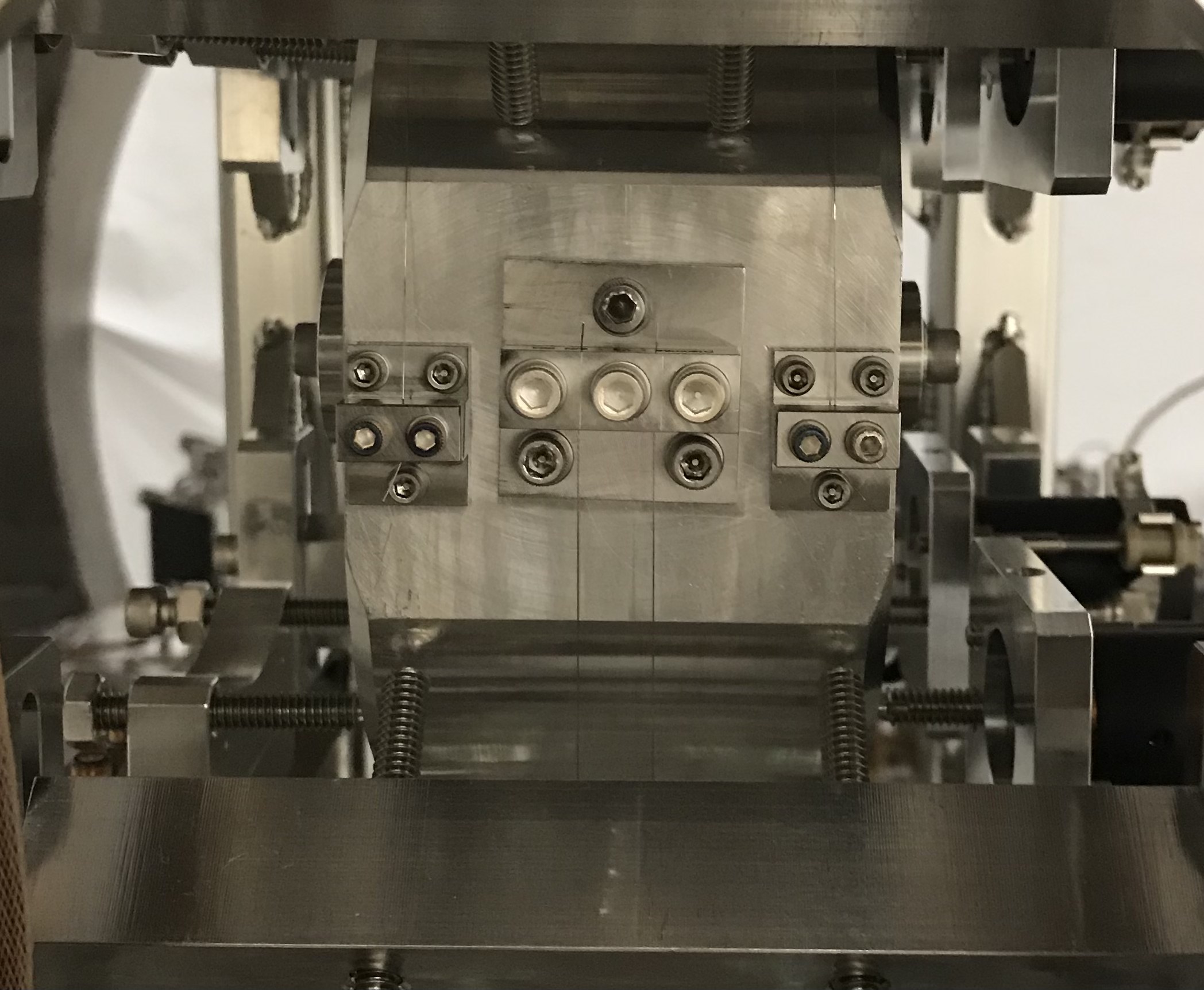
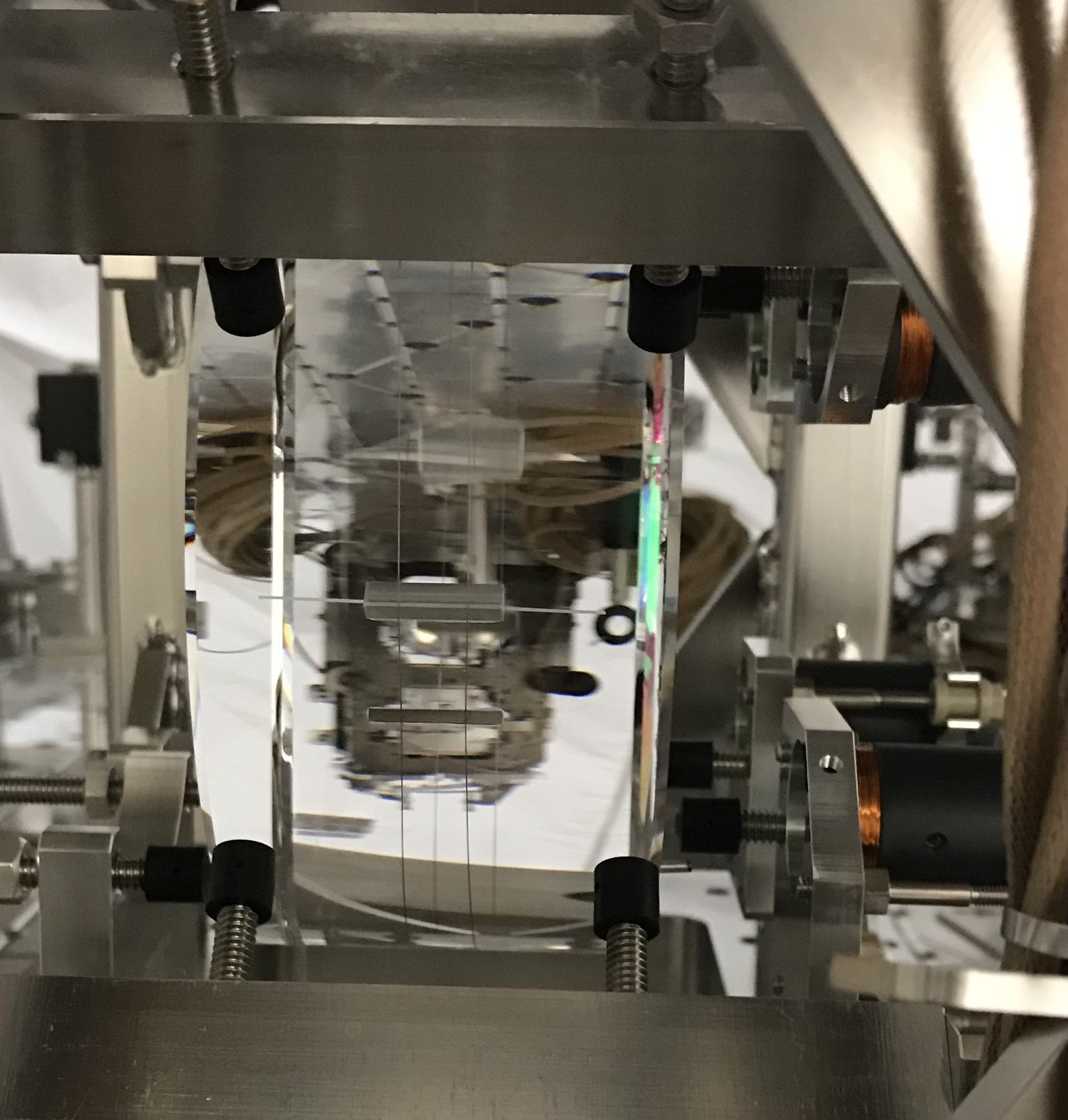
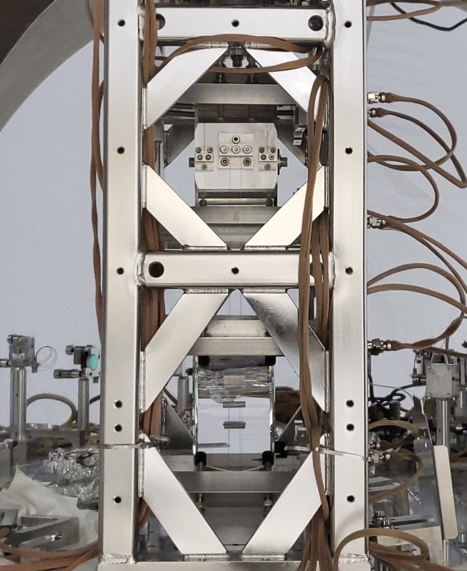
J. Kissel, R. Kumar, N. Robertson, B. Weaver

We're continuing to stew on this overnight, and have come up with a few leads, enumerated below.

First however, I want to clarify that the two modes in question are Mode P2, nominally at 3.21 Hz, and Mode P3, nominally at 3.78 Hz.
I would say that one of these modes is "missing," but instead, they've shifted, for whatever mechanical reasons, to be on top of each other.

(1) From the pages of the "Transfer Function Coloring Book," a "rogues gallery" we keep of things that can go wrong with suspensions, I found an entry that looks *very* much like what we're seeing here on HSTSs: when Incorrect (Thicker) M2 to M3 wire thickness.
    Digging further in to the aLOGs referenced, a key entry is Brett Shapiro's comment in LLO:4649, where he says
"With some parts kindly provided by Jeff B at LHO [...] a new intermediate wire was pulled and successfully installed into SRM suspension."
and
"[after replacing the M2 to M3 wires with that from LHO, the] TFs look essentially identical to those taken before, but with potentially a new R to T coupling, and the hunt goes on to find the source of the pitch problem."

Since this FC1 is the first HSTS built in a long time, this smells to me like any of the perfectly plausible things have happened:
   - LHO has a *store* of M2 to M3 wires that are the incorrect HAUX diameter wire rather than the correct M2 to M3 diamtere wire,
   - the old assembly procedure has a flaw,
   - or that the wire spool is incorrectly labeled or something.

Rahul comments via email exchange:
"These are fresh wires pulled for FC1 optic. In fact we (Bartlett and I) pulled 2 of them last year (one spare) from the same spool of wire.
After Betsy and I removed the old wire (which was used on the FC1 metal mass), I stored it in a pan along with the new spare wire."
Which doesn't rule out the possibility that the wrong wire diameter.

It'll be quite straightforward to verify this by using clean calipers and repeating Matt's measurement shown in his picture of the smoking gun for the flaw in L1 SRM's early days of Phase 1a testing.
Rahul will do this ASAP.

Other ideas:
(2) Betsy and Rahul have had a lot of problems with initial alignment of this optic. In the process, (quoting Betsy via email):
"We had to twist the side wire clamp on the intermediate mass within the slop of the screws in order to remove some differential pitch when the mass was hung. This could have been a because of prism placement errors or an error in assembling the bottom double wire loop. While you can see the clamps "crookedness" now, I think we have done this in the past in places throughout SUS."
Rahul provided the pics of this situation via email, which are now attached here.
    - FC1_M2_to_M3_wire_clamp.jpeg shows a zoomed in picture of the M2 to M3 wire clamp at the M2 stage,
    - FC1_M3_prism.jpeg shows a zoomed in picture of the M3 prism and the optic, and
    - FC1_Full_M2_and_M3_pic_sideview.jpeg shows the full view of the optic from the side.

It's plausible that this funky configuration of wire clamp and prism loop have caused what Brett describes in (1)(b) above -- "the lowest wire longitudinal spacing is too big by about 3 mm, or 1.5 mm on model parameter sl, in addition to either d3 or d4 being too large by 0.75 mm. That is sl = 6.5 mm rather than 5 mm and d4 or d3 = 1.75 mm rather than 1 mm."

(3) Norna notes that FC1 is the highest radius of curvature optic that an HSTS has ever suspended, at 1 [m] convex (e.g. M2 is "only" +28.5 [m] concave, PRM is -11 [m] convex, PR2 is +4.5 [m] concave, SR2 is -6.43 m convex), and SRM is -5.69 m). While it doesn't jive with Brett's model predictions, it's plausible that the signficant "carve out" of the 1 [m] RoC from the standard cylindrical substrate may cause significant change in Pitch moment of inertia, stiffening up these upper two pitch modes.


Finally -- to aide future coloring book entries, I attach a comparison of some transfer functions showing the best info we have.
I've taken particular care to show
   - a typical "perfect" suspension -- in this case a 2018 measurement of H1 SUS PR2 while in vacuum (with a glass optic).
   - the infamous transfer functions from the X2 / L1 SRM while it was metal, during Phase 1b of testing, well before it was installed, using test stand electronics.
   - the semi-recent 2021-01-29 transfer functions of the new H1SUSFC1, but while it still had its metal mass in place, measured chamber-side using (coincidentally) PR2's electronics chain as a mock-test stand
   - the current set of 2021-11-04 transfer functions taken this morning of H1SUSFC1, with the current alignment / clamp issues, and fishy looking transfer functions.

Depressingly, looking at the 5th page, on the M1 P to M1 P transfer functions, the current set of transfer functions show the pitch flaw but,
   - the 2021-01-29 metal TFs show a much more perfect-like split of the P2 and P3 modes -- even though Rahul claims above that the wire for the metal build and the glass loop were pulled from the same spool, and
   - the new, 2021-11-04 H1SUSFC1 combined (or, more adjacent) P2 / P3 modes don't *exactly* line up with the old X2SUSSRM combined P2 P3 mode. The 2021-11-04, H1SUSFC1, highest, green pitch mode is at 3.61 Hz, where the X2SUSSRM mode is at 3.52 Hz.
So -- it may be a combination of all three of the above ideas that may be causing the current state of affairs.

We'll see -- stay tuned! This is definitely the hardest SUS dynamical problem we've had in a long time!

I found the issue with FC1 - the bottom mass wire loop diameter is wrong. The correct spec is 0.0047'' and the one we have used after replacing the optic is 0.008". I found this out after measuring the two wires stored in the pan (the wire which we took out during optic replacement and the second one was the spare for FC1).
I will pull a fresh set of 0.0047'' diameter wires for the bottom mass later this week for replacement. Sorry for all the headache caused during troubleshooting.