jeffrey.kissel@LIGO.ORG - posted 16:52, Monday 15 November 2021 - last comment - 12:47, Thursday 18 November 2021(60645)
H1 SUS OM1 Damping Loops Improved: Above 10 Hz, Sensor Noise Suppression Better by Factors of 35-40; 1/e Ringdown Times Still Under 1 sec
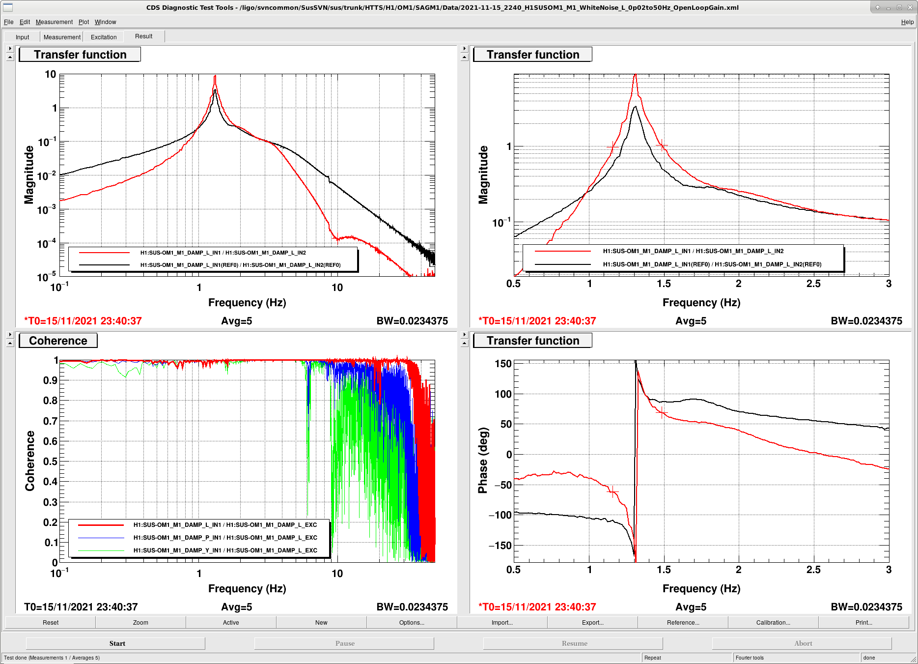
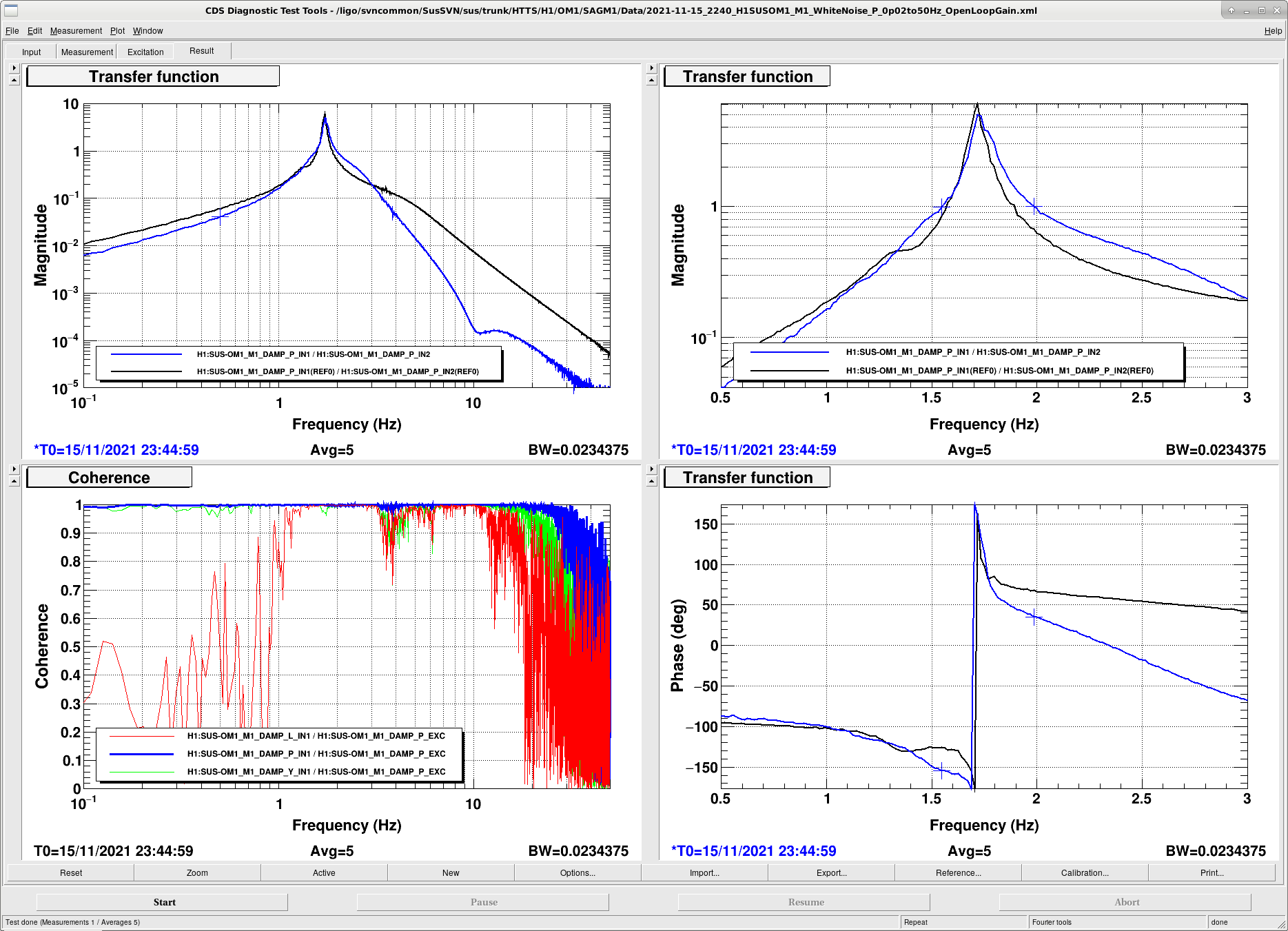
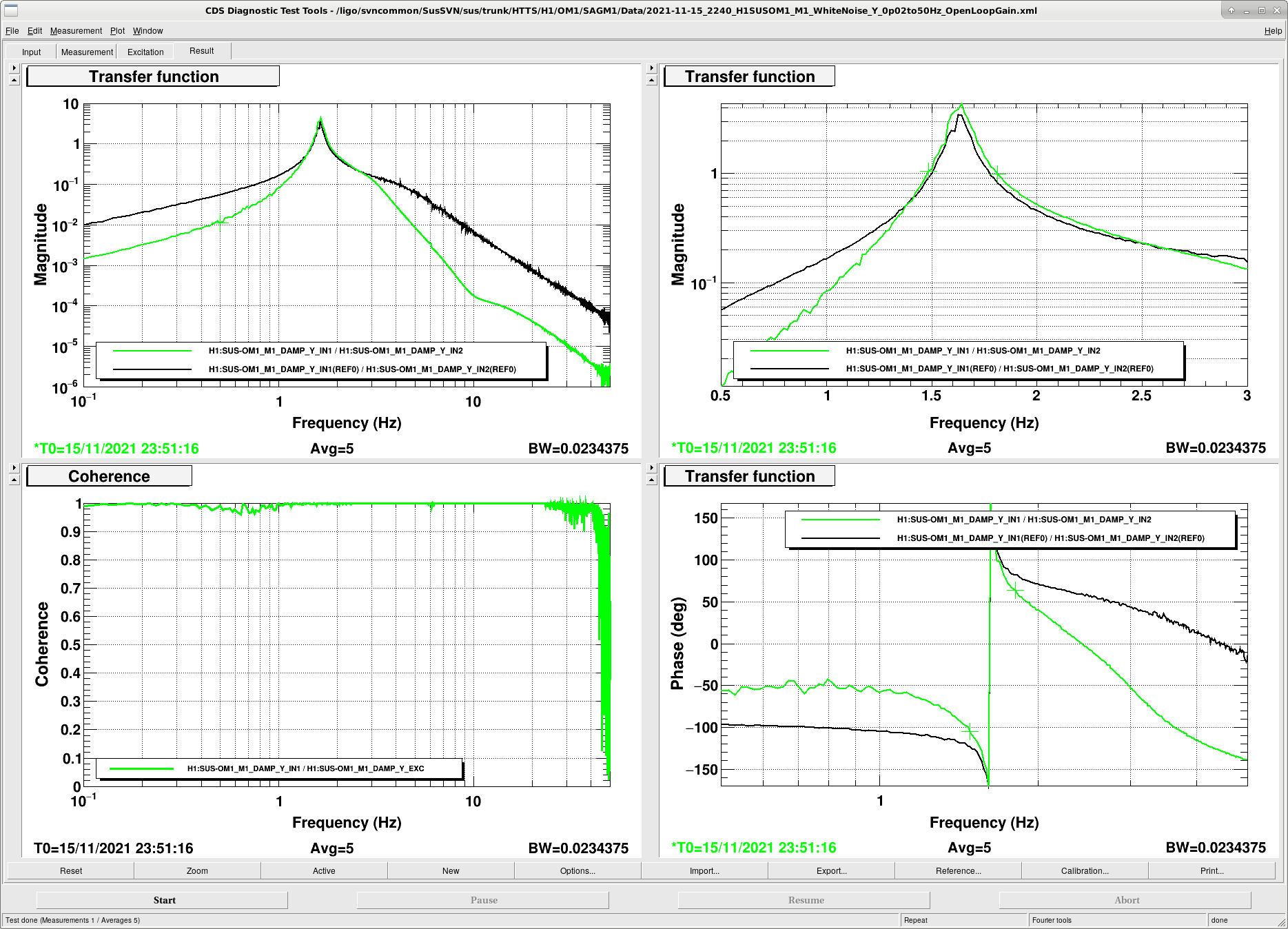
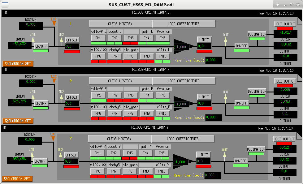
J. Kissel, V. Srivastava

Similar to the improvements made on the OMC SUS damping loops (see LHO:60049), I've now designed new filters for the HAM Tip-Tilt Suspension's (HTTS's) damping loops in order to (hopefully) complete the reduction in noise 10-50 Hz noise of the OMC-ASC loops, believed to be dominated by re-injected sensor noise (see G2102248) from the OM1, OM2, and OM3 HTTSs, as well as their 16-bit DAC noise as passed through their HAM-A coil driver (even with the increased 1.2e3 [Ohm] output impedance, a la E1201027, and hence the motivation for newer, but not yet implemented, ECR E2100430).

The attached plots show the comparison between the *measured* open loop gain transfer functions (measured in-loop with all DOFs on to properly show the MIMO results) for before and after for all DOFs. One can see with this design, we get
                                     L              P              Y
LO Lowest Lower UGF [Hz]            1.15          1.55           1.48
HI Highest Upper UGF [Hz]           1.48          1.98           1.81
Phase Margin LO/HI [deg]          61.6/68.9      155/35.3      105/64.1
Maximum Gain Peaking
   max(1/abs(1 + G))            1.30 [@LO UGF]  2.42 [@HI]      1.50 [@HI]
Factor of x Improvement
   old/new 1/e Ringdown time       x 1.4         x 0.7          x 1.0
   10 Hz Suppression               x34.5         x41.5          x 36.8
The pitch loop is arguably aggressive, but it still should be quite stable even under ~10% gain fluctuations or 1% mode frequency fluctuations (neither of which we expect).

I'll add comments and details about the design below.

These new damping loops are installed, running, functional on OM1, OM2, and OM3, their configuration has been saved into the SDF system, and the foton file is committed to the userapps repo.
The run with FM1, FM2, FM4, FM5, and FM10 on (PITCH does not use a boost, so FM2 is not on in that DOF).
For future comparison of "old .vs new" filters, I've shoved all of the old filters and gains in to FM6, FM7, and FM8.
Images attached to this report
Comments related to this report
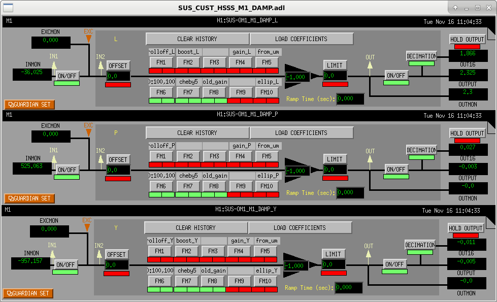
The MEDM Configuration

2021-11-16_H1SUSOM1_DAMP_MEDM_NewFilterConfiguration.png: I show a screenshot of how the M1 DAMP filter banks should be configured to turn these new damping filters on. All scalar gain that's tailored to each degree of freedom is hidden / hard-coded in the "gain_{DOF}" FM4 filter module, such that all DOFs should be run with an EPICs gain of -1.0.

2021-11-16_H1SUSOM1_DAMP_MEDM_ReproduceOldFilterConfiguration.png: I show a screenshot the same filter bank configured to reproduce the old damping filters, if need be.
Images attached to this comment
 The Filter Design

The above filter design was aided my the following matlab functions and scripts:
- A pretty substantial update to ${SusSVN}/Common/MatlabTools/make_OSEM_filter_model.m, which
    - now includes references to all the newer actuated SUS that have appeared since O1 -- the OPOS, the OFIS, the HXDS
    - adds some new fields to the output variable coilDriverModel to support differentiating between a 16-bit DAC and an 18-bit DAC
    - adds the choice of a modified HAM-A driver response, as described/proposed/approved in ECR E2100430 and supporting technical note T2100410.

- Some minor updates to Common/MatlabTools/createdampingfilterstruct.m to allow for a choice between 16-bit DACs and 18-bit DACs when calibrating filters for modeling purposes (a need, for the first time, with HTTSs)

- Brand new functions to compute and plot figures of merit for HTTS loop design, including
    - ${SusSVN}HTTS/Common/FilterDesign/Scripts/plothttsdampingcontroldesign.m and
    - ${SusSVN}HTTS/Common/FilterDesign/Scripts/plothttsactuatornoise.m

- Which all are verified and checked by replicating and modeling the performance of the *old* filters, with
    - ${SusSVN}HTTS/Common/FilterDesign/Scripts/design_damping_HTTS_20141206_H1SUSOM1.m, which produces the first attached set of plots,

- Then, I design the new filters with two scripts that differ only in the modeling of the actuator noise comparing an unmodified D1100117-v4 HAM-A driver circuit against a T2100410-like modified HAM-A driver,
    - ${SusSVN}HTTS/Common/FilterDesign/Scripts/design_damping_HTTS_20211115.m
These produce the second and third set of attached plots.

- And finally compare all three using the script
    - HTTS/Common/FilterDesign/Scripts/compare_htts_dampfilter_design.m
which produces the fourth and final set of plots.

 Commentary on design

As I'd had to do with the OMC damping loop design, when *actually implementing* this design I needed a fudge factor gain of 70 in order to match the predicted open loop gain transfer function magnitude. This appears to be a systemic problem with my modeling infrastructure, but at least, thankfully, it appears to be a common gain across multiple suspension designs. However, this doesn't nullify the useful ness and function of the frequency dependence of my design, so as before, I just scaled the *measured* open loop gain transfer function to match the model. It now makes me wonder if this is what went wrong when I tried working with Anamaria to install similarly modeled damping loops for the HSTSs at LLO.

But, this unfortunately means I'm no longer *super* confident of the relative scale of the terms within noise budget model -- and thus equally unsure of the total prediction -- of the displacement of the optic. And yet, there is still merit in showing the results -- especially in terms of comparing the changes in term amplitude between the different designs.

One thing that is clear from the *measurement* of the installed filters open loop gain transfer function (with the fudged gain): the damping loop design performance is clearly better in terms of sensor noise rejection, and there's little to no change in the amount of damping time / resonant Q reduction. So -- at least -- the goal of the design has been achieved. Whether the prediction of the noise budget -- that in all cases, the suspension's optic displacement will be dominated by 16-bit DAC noise transmitted through either the unmodified, or even after the modified HAM-A driver low pass filter -- is true, remains to be seen.

I'm glad that I had the foresight to retain the old filter design -- given all the uncertainty in the OMC-ASC loop noise modeling, I think it'll be worth a test of switching to and from these new damping filters once we get the IFO back. Indeed, I might argue the same is true for wanting a measurement of the OMC-ASC noise before vs after installing the modifications to the HAM-A drivers.
Stay tuned on that.
Non-image files attached to this comment
