J. Oberling, V. Srivastava, E. Capote
Primary goal today was to tweak up the FSS path alignment. This had changed with the rise in enclosure temperature and needed to be recovered. Background: When we first set up the FSS path in December 2021 we were keeping the enclosure at ~20 °C, but now that we have the system running and the enclosure in Science mode the ambient temperature is closer to 23 °C (the ACs are now set so the enclosure temp is closer to 23 °C while we're working, to avoid large temperature transients). This temperature change, as we've seen many times in the past, caused a misalignment in the FSS path, and my suspicion was that the AOM mount is the source of this misalignment.
However, before we started that we took a quick look at PMC mode matching optimization. We recorded the start position of the mode matching lens micrometers, and then proceeded to move the lenses to see if we could quickly improve the power transmission of the PMC (initial mode matching was done without the ISS AOM installed, so with the AOM in we need to tweak our mode matching). We could not get any improvement with adjustments on the order several millimeters, so we put the lenses back in their start positions and moved onto the FSS path. Looks like optimizing the PMC won't be as quick as I had hoped. Ah well.
Moving on to the FSS path alignment, as previously stated the suspicion was that the double-pass AOM had moved with the temperature change, so we did a power budget around this AOM:
- AOM In: 296.0 mW
- AOM Out: 131.0 mW
- Single-pass diffraction efficiency: 44.3% (!!!)
- EOM In: 83.3 mW
- Double-pass diffraction efficiency: 63.6%
The single-pass diffraction efficiency should be closer to 70%, so our suspicion was correct, the AOM had moved with the temperature change. We first tried adjusting the AOM alignment with the RefCav locked, but weren't confident we were moving in the right direction so we used a power meter to adjust the AOM for maximum single-pass diffraction efficiency. That done we then adjusted mirror M21 to max the double-pass diffraction efficiency. Final results:
- AOM In: 296.0 mW
- AOM Out: 201.8 mW
- Single-pass diffraction efficiency: 68.2%
- EOM Out: 147.2 mW
- Double-pass diffraction efficiency: 72.9%
Much better. We used the iris in front of the RefCav to recover the beam alignment and locked the RefCav without issue. The TPD was ~0.33 V upon relocking (recall that we now have a factor of 10 filtration in front of the TPD, so 0.33 V is equivalent to 3.3 V when compared to O3 RefCav TPD). This was ajdusted using the picomotor controlled mounts, and our final TPD is 0.94 V. We then unlocked the RefCav and tweaked the beam alignment onto the RefCav RFPD. While here, we measured the locked and unlocked voltage on the RFPD and calculated the RefCav visibility:
- Unlocked: 1.250 V
- Locked: 0.23 V
- Visibility: 81.6%
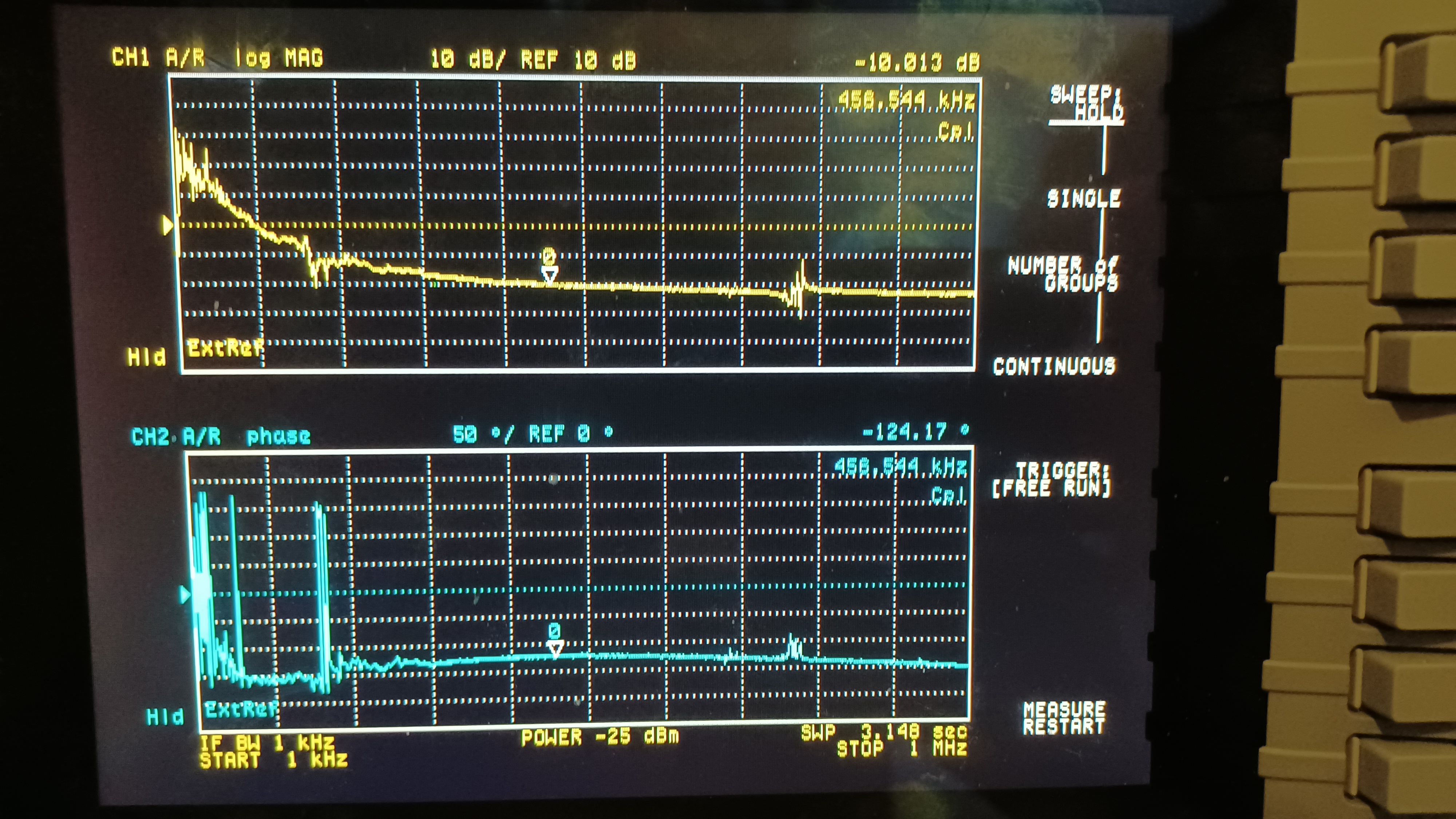
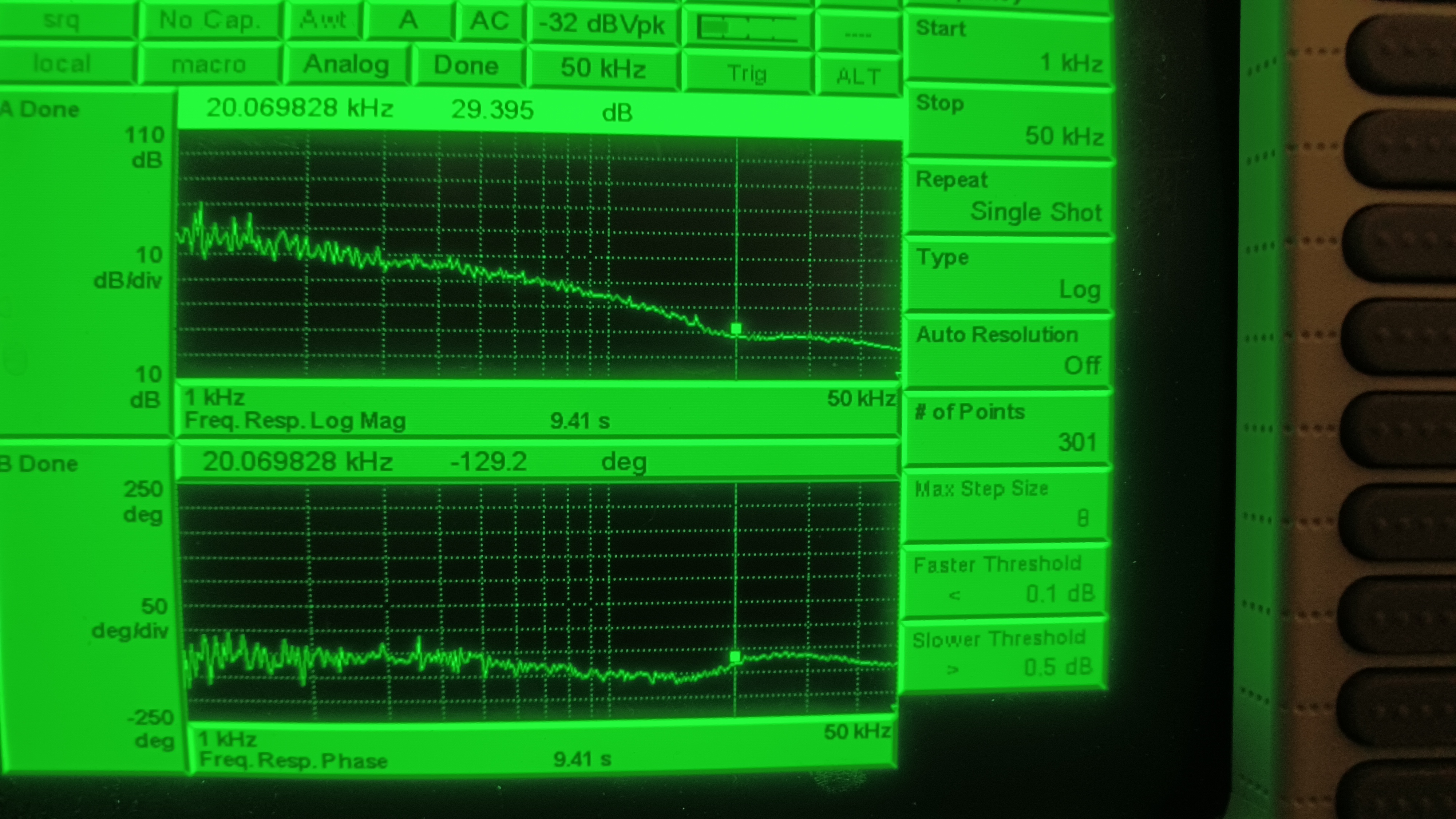
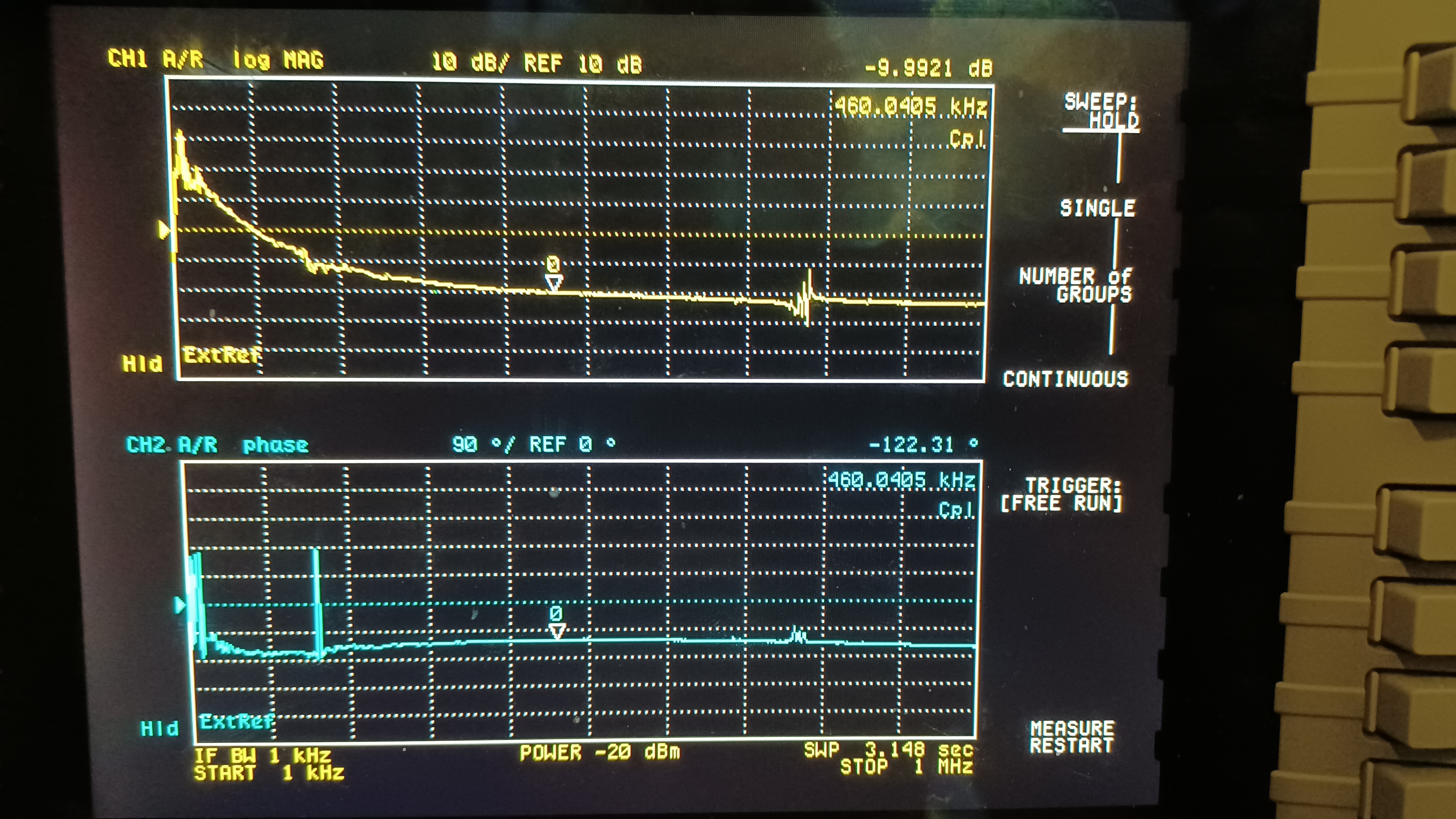
We know there's some mode matching work to do on the RefCav, but in the low-80% range is where we've been for a while, so this looks good. That done we relocked the RefCav, left the enclosure and put it in Science mode, and measured the FSS TF (we can do this from outside now!!!). The first attachment shows the FSS TF with a common gain of 15 dB (used to be 20 dB, but that gave a UGF of over 700 kHz; we want to be closer to 500 kHz) and a fast gain of 13 dB (unchanged). The 2nd attached image is the crossover region (20 kHz to 25 kHz; we switched to the SR785 to see this better). There was horrible gain peaking here with the fast gain at 13 dB so we lowered it to 8 dB, which smoothed things out nicely. Since we changed the fast gain, we re-measured the TF to make sure all was still good, this is the final attached image. Final settings:
- Common Gain: 15 dB
- Fast Gain: 8 dB
- UGF: 460 kHz
These setting were accepted in SDF.