jeffrey.kissel@LIGO.ORG - posted 19:30, Tuesday 26 April 2022 - last comment - 17:14, Friday 29 April 2022(62837)
All H1 SUS HXDS M1 Damping Loops Improved and Characterized
J. Kissel, B. Ratto
Many more details to come, but the title says it all:
- We've designed new "Level 2" style damping loop filters for the HXDS
- We've installed those new filters, and
- We've measured the open loop gain transfer functions, which
- Confirmed that we get (roughly) the expected loop gain we want, and that
- the loops are
- stable, with plenty of phase margin (typically in the ~45-50 deg range)
- improve ring-down times and reduce Qs, especially for P and Y
- don't re-inject too much sensor noise
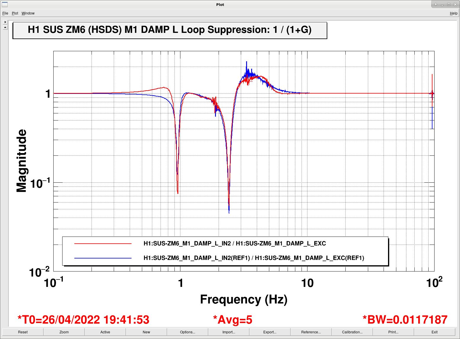
- don't have loop suppresion gain peaking of more than a factor of 2.
- We've committed the new filter files to the userapps SVN, and
- We've saved the settings in the SDF system
Remember, HXDSs cover ZM1, ZM2, ZM3, ZM4, ZM5, and ZM6. We've installed these improved control filters on all of them, and took the time to characterize all of them.
Attached are a few teaser plots showing
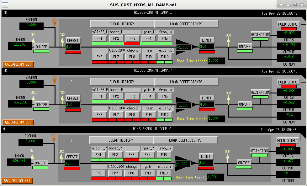
(a) a screenshot of how we've laid out the MEDM filter bank for each HXDS, and
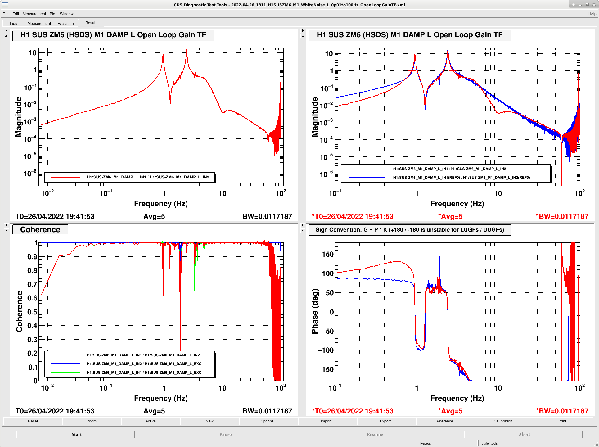
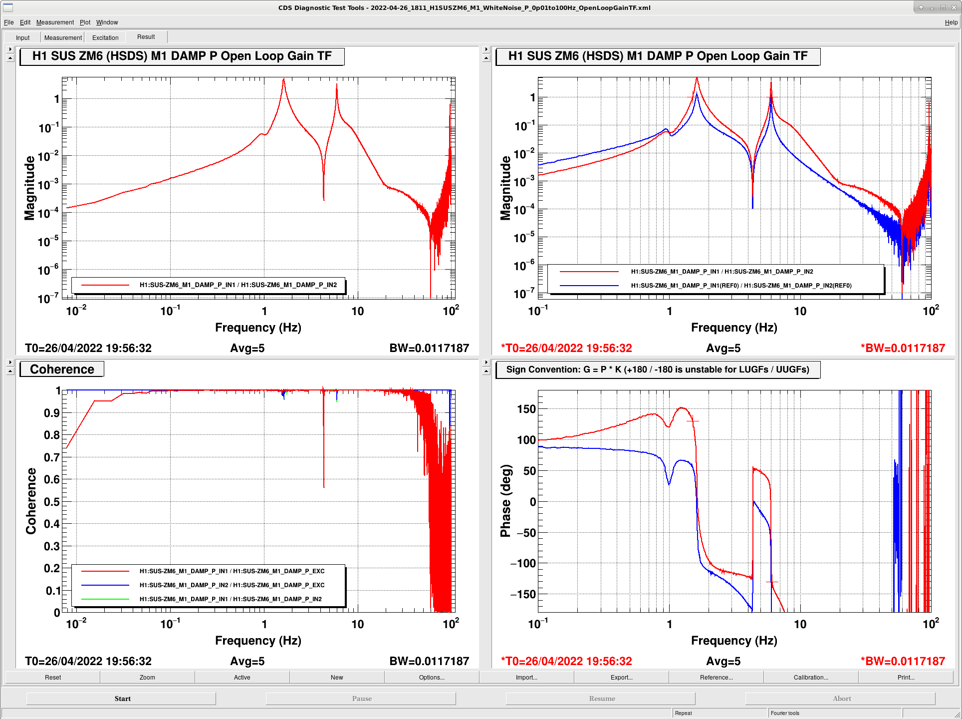
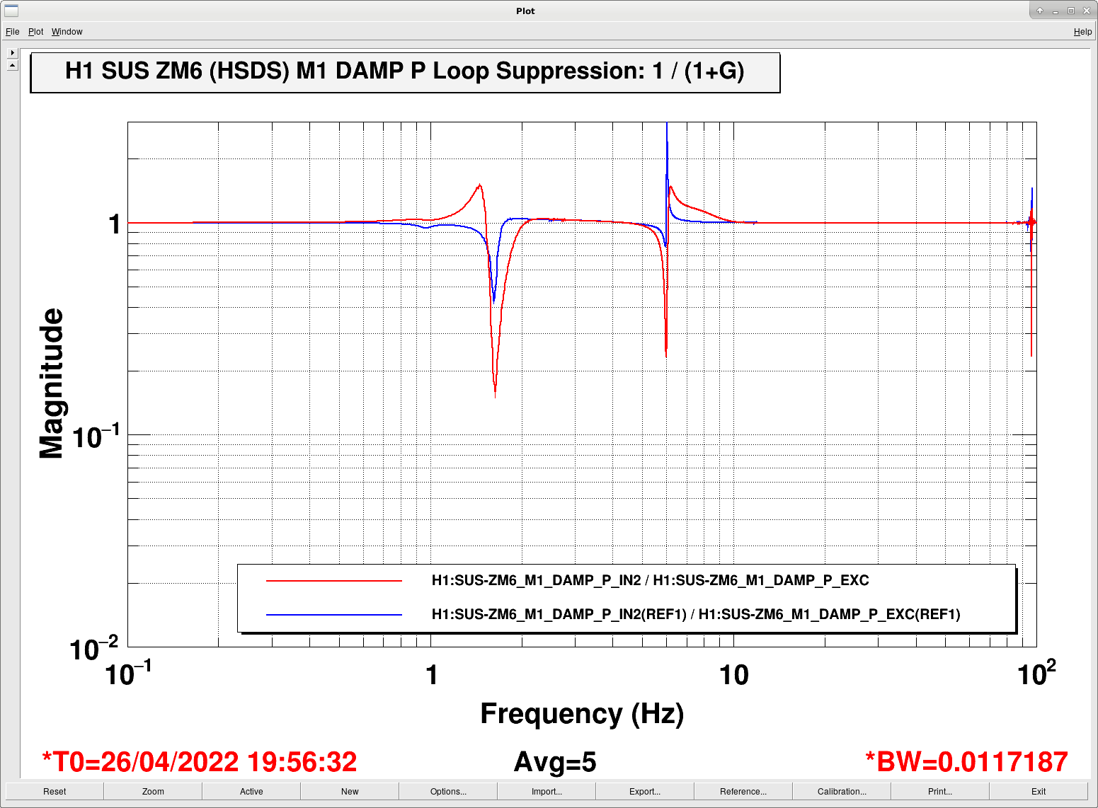
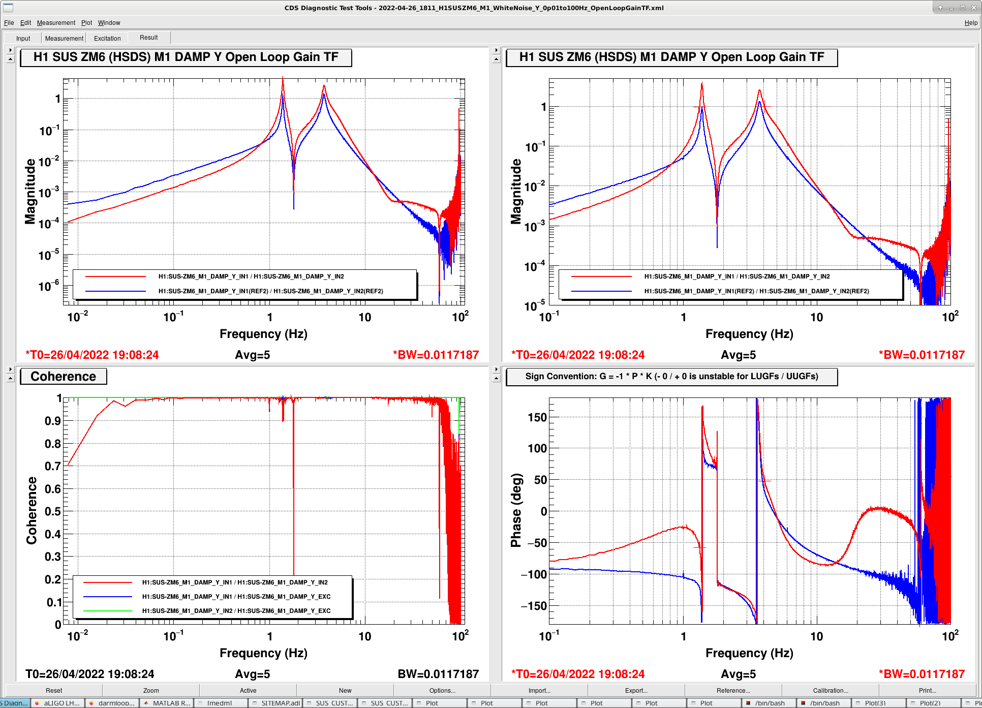
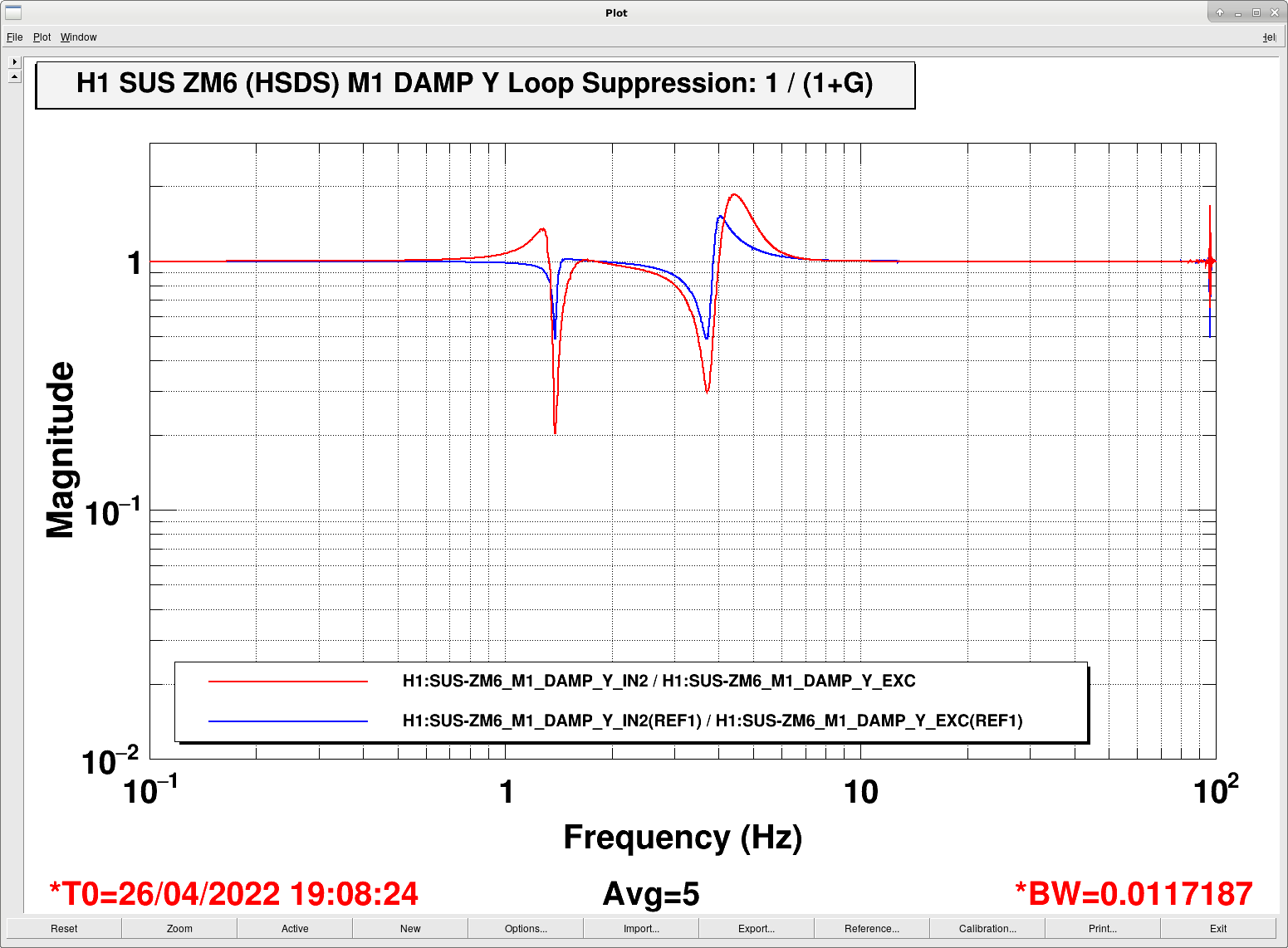
(b) For ZM6, the open loop gain TFs and loop suppression for all three DOFs, L, P, and Y.
In the (b) plots, the
- RED traces are the new design, and
- BLUE traces are the former "design"
(I put the former "design" in quotes because there has really been no intentional work done in P or Y prior to now. They've been copies and pastes of bad old HTTS filters, with an arbitrary gain -- and this was done by *me* just to get the things working back in Fall 2021.)
While there are *subtle* differences between the specific types of HXDSs, be they HSDSs (ZM6), HPDSs (ZM2, ZM4, ZM5), or HDDSs (ZM1, ZM3), because of the differences in the plant (as discussed in LHO:62779), they're subtle enough that we can safely use the same exact filter design, with the same exact gain, for all HXDS, and get equally good results as shown for ZM6.
Stay tuned for further details.
Images attached to this report
Comments related to this report
The HXDS 'Level 2' Filter Design Tools and Scripts

The above loop design was aided by the following updates to existing functions, and the creation of the following new functions:

To ensure we have a good dynamical, double pendulum, model parameter set that's representative of our real HXDSs:
    - we compared
        ${SusSVN}/trunk/Common/MatlabTools/DoubleModel_Production/hxdsopt_doublep.m
    against all of the latest and greatest measurements.
See LHO:62779 and commentary therein. In short: the model has about 10% more magnitude than the measurements, and the HPDS have a little bit different resonant frequencies, but that should only make the *real* loops less aggressive, since we'd be modeling with a higher inherent plant gain.

To create a good residual seismic noise estimate for all DOFs:
    - Used
        o HAM5 and HAM7 systems drawings for the X / Y / Yaw of the HXDS, and the spacer heights
            :: D2100006 for ZM6 (HSDS),
            :: D2100373 for ZM1, ZM3 (HDDS), and
            :: D1900363 for ZM2, ZM4, ZM5 (HPDS)), and
        o HXDS assembly drawing (D2000466) for the height between the spacer / base to the suspension point,
     to populate all the parameters for H1's ZM1, ZM2, ZM3, ZM4, ZM5, and ZM6 in
        ${SusSVN}/trunk/Common/MatlabTools/SEI2SUScoordinates.m

    - Added these ZMs (the HXDSs) to the list of optics to compute projections for in
        ${SusSVN}/trunk/Common/MatlabTools/make_ISI2SUS_projections.m

    - Ran make_ISI2SUS_projections.m, such that it produced an updated projection matrix structure, which we keep in ${userappsSVN}/isc/common/projections/ISI2SUS_projection_file.mat

To create a good actuator noise estimate:
    - used the same work done already in the new HTTS loop design (LHO:60698) to obtain a good model of the HAM-A + BOSEM, DAC though coil driver, actuator noise, and using the recently validated dynamical model created
        ${SusSVN}/trunk/HXDS/Common/FilterDesign/Scripts/plothxdsactuatornoise.m

With all these noise estimates, we project the used the function talked about first in LHO:62780,
    ${SusSVN}/trunk/HXDS/Common/FilterDesign/Scripts/plothxdsdampingcontroldesign.m

with the brand new design script,
    ${SusSVN}/trunk/HXDS/Common/FilterDesign/Scripts/design_damping_HXDS_20220425.m

Note, I think we've finally resolved the confusion about the factor ~40-50 that was needed between my loop designs and reality, and that was resolved with an updated version of
    - /trunk/Common/MatlabTools/createdampingfilterstruct.m
The HXDS 'Level 2' Damping Loop Design Metrics for Success

The above mentioned infrastructure spits out lots of metrics for success:
For L, P, and Y,
    - A comparison between the filters, in "foton" units,
    - A comparison between the filters, in "calibrated" N/m or (N.m)/rad.
    - The loop design itself, including the modeled
        :: The plant, P
        :: The controller, K
        :: open loop gain transfer function, both SISO G = P*K version and full state-space MIMO version
        :: loop suppression, 1 / (1 + G)
        :: closed loop plant, P / (1 + G), both SISO and MIMO
    - The impulse response, to show the "ring down" 1/e time
    - The noise term component breakdown of all DOF's contribution to the optic's L P or Y displacement
    - The "final" noise budget, comparing the re-injected sensor noise against the estimated (fixed) residual seismic noise, actuator noise, and requirements

Attached are these results, which have been saved to
    ${SusSVN}/trunk/HXDS/Common/FilterDesign/Results/dampingfilters_HXDS_ZM6_2022-04-25.pdf
and exported to .mat files here:
    https://svn.ligo.caltech.edu/svn/sus/trunk/HXDS/Common/FilterDesign/MatFiles/
        dampingfilters_HXDS_ZM6_2022-04-25.mat
        dampingfilters_HXDS_ZM6_2022-04-25_model.mat

Commentary

This is a (what's now come to be) standard 'Level 2' design: in the face of little-to-no apriori requirements, the goals are:
    - Reduce the Qs of the loop-suppressed plant on resonance as much as possible,
    - Reduce the ring-down time to 1-2 seconds, and
    - Have plenty of phase margin to account for small plant gain and resonant frequency differences, but
    - without re-injecting more sensor noise than the "fixed" residual seismic and actuator noises above ~10 Hz.

We we able to (mostly) achieve all of these goals.
    - (Page 9) We easily meet the requirements defined by the thick-dashed green traces in figures 6, 7, and 8, of T1800447 which define the length displacement noise requirement, which is the only well-defined requirement.
    - (Pages 9, 16, and 23) The re-injected sensor noise above ~10 Hz for all DOFs "rides along" the residual seismic and actuator noises, either comparable to or no more than a factor of ~2 above it.
    - (Pages 4, 11, and 18) All 1/e ringdown times are ~1.5 [sec], though the 6 Hz pitch mode does continue oscillate for quite a while after the 1/e time. This is because that highest pitch mode is at 6 Hz, making it quite a challenge to damp while still having enough phase margin left to get good sensor noise rejection at 10 Hz with our trusty low-Q elliptic low pass. There's no point in making a quantitative statement about Q reduction.
    - (Pages 3, 10, and 17) The phase margins are all above 30 deg, with Y at 31, P at 32, and Y and 50 degs.
Non-image files attached to this comment
