keita.kawabe@LIGO.ORG - posted 17:42, Friday 21 October 2022 - last comment - 16:46, Monday 31 October 2022(65422)
T-SAMS seems to work. Single bounce X OMC scan isn't great at the moment.
Good news is that T-SAMS seems to be doing something (look at the last column of the table), so that part of the test is OK.
Single bounce (X) OMC scan shows that more than 10% is lost to 02 mode carrier at the moment. The higher the T-SAMS heating, the worse, but the heating effect is not that large (as expected).
The alignment of the beam into the IFO is questionable (I didn't do any meaningful initial alignment for corner IFO itself) and it's not impossible that the beam is clipped somewhere between IMC and HAM6. Also, is ITMX TCS good?
| Slope start [UTC] | Slope end [UTC] | Heater request [W] | Thermistor2 temp [C] | C20 mean [mA] | C00 mean [mA] | 20/(00+20) |
| 2022/10/21 01:13:35 | 01:14:58 | 0 (still cooling) | 29.3 | 0.208 | 1.708 | 0.109 |
| 02:17:28 | 02:18:50 | 4.4 (still heating) | 54.8 | 0.233 | 1.670 |
0.124 |
| 16:41:23 | 16:42:44 | 4.4 (still heating) | 56.0 | 0.235 | 1.696 | 0.121 |
| 18:21:23 | 18:22:43 | 7.3 (still heating) | 72.8 | 0.250 | 1.641 | 0.132 |
| 20:04:09 | 20:05:30 | 0 (still cooling) | 26.0 | 0.208 | 1.698 | 0.109 |
| 22:14:42 | 22:16:04 | 0 | 24.7 | 0.202 | 1.691 | 0.107 |
| 22:20:16 | 22:21:37 | 0 | 24.66 | 0.2064 | 1.698 | 0.108 |
| 23:07:29 | 23:08:51 | 0 | 24.54 | 0.2025 | 1.685 | 0.107 |
What was done:
- IMC power 2W.
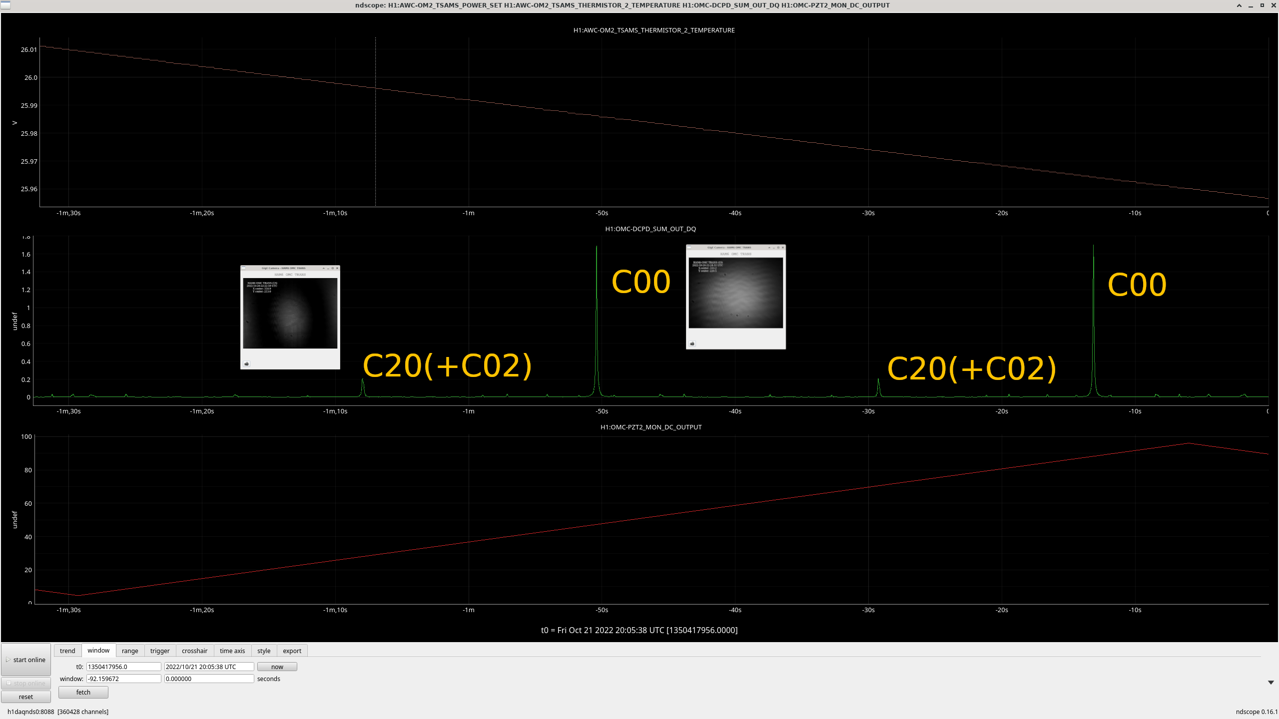
- Scan OMC length by repeating sawtooth waveform wide enough that I always get two 00 carrier peaks and two 20 carrier peaks in each slope of the sawtooth (1st attachment, note that the video for C20 has a larger integration than C00). Scan rate and the power were small enough there was no saturation in the whitening of OMC DCPD.
- Change T-SAMS heating, wait, and record the height of 00 carrier and 20 carrier.
- Different PZT voltage results in slightly different OMC mirror tilt, which results in different OMC alignment relative to QPDs. For this reason I just took an average of two peaks for 00 per scan slope. Same thing for 20.
- OMC ASC was feeding back to OM1 and OM3 to center OMC QPDs with nominal offsets all the time. If alignment changed, it should have been absorbed by this.
- Since 00 and 20 carriers dominated, and since I was initially only interested to see if T-SAMS worked, I ignored all other peaks (carrier 10, 30 and higher, all RFSBs) and made 20/(00+20).
Note:
-
In the past, Elena's 50W and 60W single bounce scan looked more than 2 times better (alog 62883). For example, C00~67mA and C20~3.2mA for 50W X, C20/(C20+C00)~0.046.
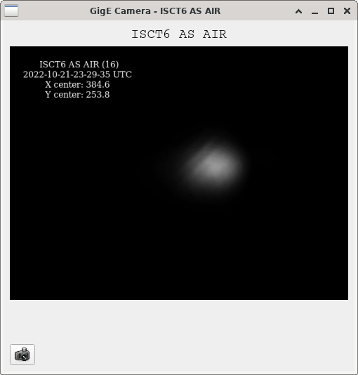
- IF the beam coming into HAM6 is good, this is a problem. AS AIR beam image doesn't look terrible but it might have elongated tail in -X direction on the AS air camera (2nd attachment), maybe it's just the camera. Anyway, tedious alignment study is needed.
- 00 and 20 mode identification is based only on the OMC TRANS camera. 20 mode looks more like HG20 to me, not a bull's eye, though it's hard to say.
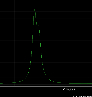
- On a close inspection, "20 peak" seems to be split into 20 and 02 (3rd attachment).
- The measurement started while ITMX was aligned and ITMY misaligned. At some point ITMY was "aligned" and both of the beams came into HAM6, but this didn't affect the measurement. When I and Tony attached the AS AIR camera to HAM6 yesterday, we confirmed that ITMY beam is too far from ITMX beam when "aligned" with the current slider values and won't even hit the AS AIR camera (it came into the camera enclosure). That's still the case today judging from the camera image.
Images attached to this report
Comments related to this report
I processed Keita's OMC scans using/ligo/gitcommon/labutils/omc_scan, e.g. for the last scan abovepython OMCscan.py 1350428867 83 "2W input, Single bounce ITMX, OM2 heater request 0W, fifth scan" "single bounce" --verbose --make_plots -p 0.01The results are shown in the same order as the table in Keita's alog: 1) OM2 heater 0W, first scan 2) OM2 heater 4.4W, first scan 3) OM2 heater 4.4W, second scan 4) OM2 heater 7.3W 5) OM2 heater 0W, second scan 6) OM2 heater 0W, third scan 7) OM2 heater 0W, fourth scan 8) OM2 heater 0W, fifth scan
With those processed OMC scans, I doubled checked the finesse of the OMC like we did for the scans back in April in alog 64582.

The HWHM is 0.338 MHz in Keita's measurements, and the FSR is 265 MHz, meaning the finesse is still 392, same as in April 2022.

This was done using /ligo/gitcommon/labutils/omc_scan/fit_peak.py
Non-image files attached to this comment

Keita and I looked at the 20 and 02 mode spacing for the carrier both now and in April 2022. We expected to find 0.3 MHz mode spacing between 02 and 20 modes, according to Koji's Final Design: T1000276 Table 1. We checked the numbers for our installed OMC as well, as posted in DCC T1500060 Table 25. This reports a larger mode spacing than the final design, with horizontal spacing = 58.138 MHz and vertical spacing = 57.844 MHz. This is a difference of 0.294 MHz. For 02 and 20 modes, we expect a separation of 2 * diff = 0.588 MHz. We found around 0.55 to 0.6 MHz separation between 02 and 20 for our mode scans, see the attached plots. This is in good agreement with expectation from Koji's lab measurements for our OMC. The power loss to HOMs cannot be easily read from OMC scans because of the overlapping modes. Here, we see the power in the 00 mode is 1.687 mA from the 2W omc scan fit above. The power in the 02 and 20 modes are 0.105 mA and 0.188 mA, respectively (we think).Analysis codeCode is in/ligo/gitcommon/labutils/omc_scan/fit_two_peaks.py, should work inlabutilsconda env. We note that we forced the HWHM to be 0.335 MHz in our two-Lorentzian peak fitting routine due to some weirdness with preferring a too-high HWHM.
Non-image files attached to this comment