hsiang-yu.huang@LIGO.ORG - posted 19:43, Wednesday 08 March 2023 - last comment - 18:01, Friday 10 March 2023(67863)
Continue to investigate the DAC-driven measurement model deeply
H. Y. Huang, J. Kissel
Pointed out by (LHO:67865). I overplot A and B path model with measurent data this time. It is the first time to show both path.
The attachment:
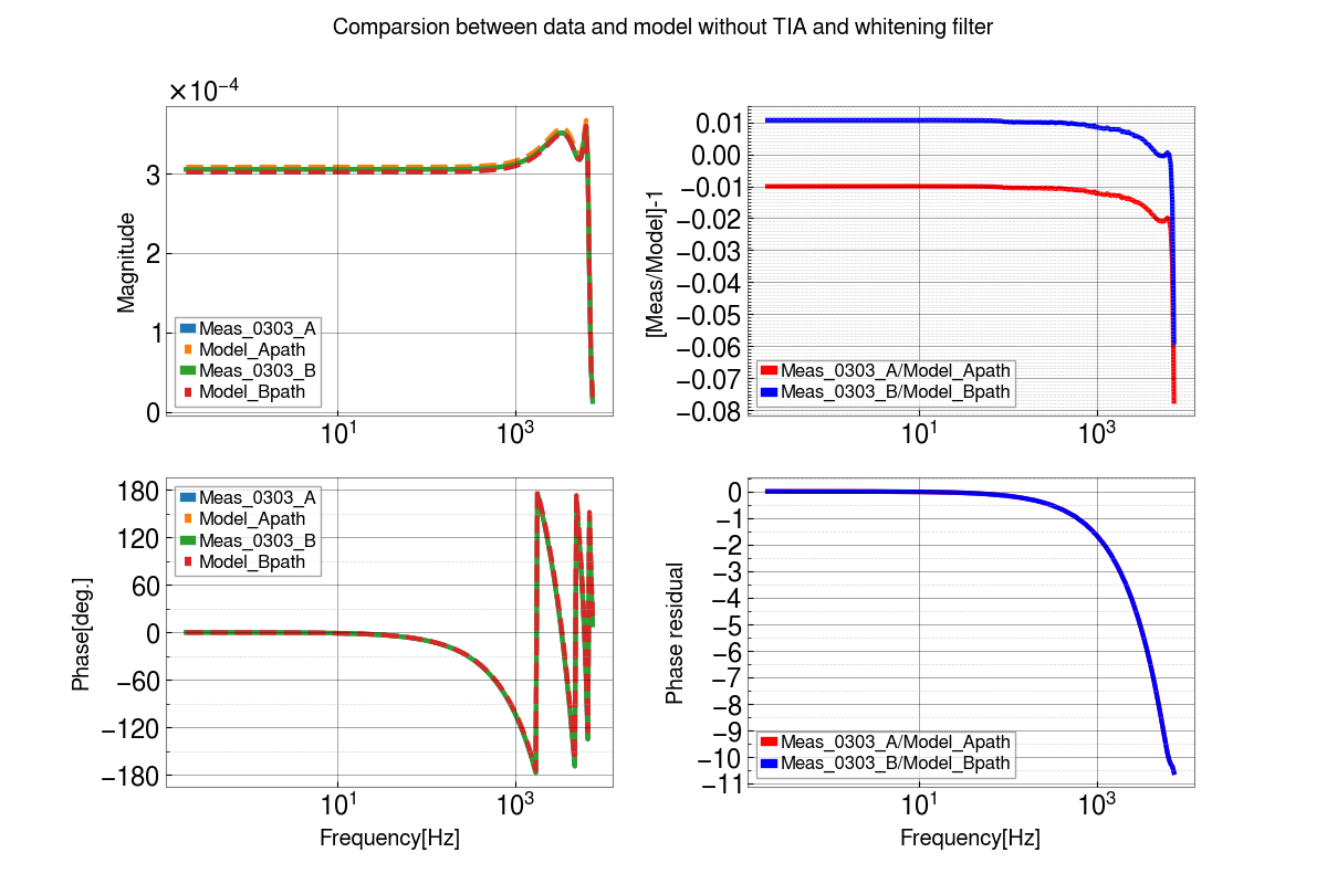
Figure 1 : Magnitude and phase of the A and B path model and data are shown in left side. The magnitdue and phase residual are shown in right side. In this plot, we still use
balance_matrix = 1.01039, 0.98961 # Old stale numbers still in place, read directly from MEDM 2022-05-22 JSK
We can see ~0.01 in B path magnitude residual and ~ -0.01 in A path magnitude residual.
But, this is wrong. In our measurement, we don't measure the DCPD output there. That means no need to use above value mostly comes form OMC beam splitter ratio.
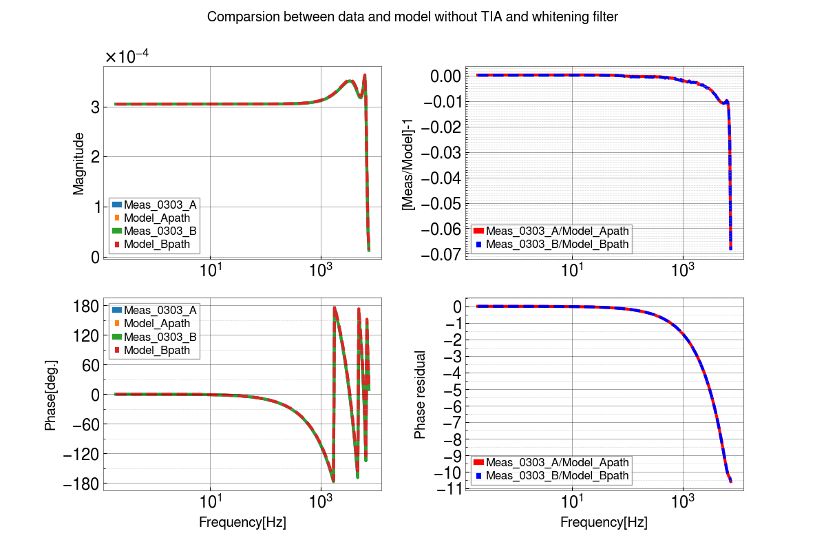
Figure 2 : In this plot, we replace values to the following in INI file:
balance_matrix = 1, 1
The gain degeneracy is gone!! This makes me feel good now.
Images attached to this report
Comments related to this report
Also now updated in this model -- an ADC volts to OMC user model delay of 9.6 usec.

Attached is the graphical representation of what Daniel describes verbally in LHO:67858, which I repeat here, and augment with a bit more words for convenience.

[[All "cycles" mentioned below are 524 kHz clock cycles, at 1/2^(-19) ~ 1.9 usec each]]
1. The sensing delay of a test point taken from the iopomc0 model is 4 cycles at 2-19s.

2. The sensing delay from the iopomc0 to the omc user model is −3 cycles + IOP delay = 5 cycles at 2-19s.

The "IOP delay" is 8 cycles.

There isn't a simple processing delay between 1 and 2, some of it is just a difference in the timestamp. The 524 kHz ADC data is sampled and processed at the IOP speed of 65 kHz, meaning 8 samples are processed at a time. Looking at the data samples around a GPS synchronized 1 PPS, the readout of these 8 samples includes data from 4 cycles ahead of the 1PPS, and 3 cycles behind. Then, the IOP processes that data, filtering it and decimating it, and then time stamps all 8 samples of 524 kHz data, with the first sample stamped at t=0 of the 1 PPS. All 8 samples are then stored in the IOP data block associated with the 1 PPS. Because there were 4 ADC points read ahead of the 1 PPS, there becomes an apparent timestamp error where the data in the frame or test point is 4 cycles delayed behind when the voltage was physically read by the ADC.

In parallel, after all 8 samples are processed by the IOP its last output is forwarded to the user model, which in turn is started with the timestamp associated with the 1PPS. This results in an apparent timestamp error where the data is advanced by 3 cycles.

Finally, since the DCPD signals use an IPC block to forward the data to the user model, another 8 cycles of delay is added, together resulting in a total delay of 5 cycles at the input of the user model.
Non-image files attached to this comment
