filiberto.clara@LIGO.ORG - posted 13:32, Tuesday 22 August 2023 - last comment - 18:24, Tuesday 22 August 2023(72377)
PEM ESD VMON Cables EY/EX
Cable clean-up of the VMON channels for monitoring the ESD 18V and 48V power lines. Signals tied to the power lines through BNC bulkheads on the junction box (top of rack). Voltage divider boxes are installed in series. Signal routed through PEM test panel to AA chassis. See attached pictures. Will work with PEM group to see how we want to isolate the divider boxes and route cables.
Images attached to this report


Comments related to this report
Got a debrief from Fil on this -- his sentences can be interpreted as a bulleted list describing the *existing* system, not anything that he installed today. The only he did today was install a *new* BNC cable run from the VEAs' SUS-C1 to the CER TSC-C1 racks, without connecting them to anything and instead terminating both ends with 50 Ohm terminators.
I can expand on his words a bit to give the reader a better feel for the existing system:
"Cable clean-up of the VMON channels for monitoring the ESD 18V and 48V power lines."
He's investigated moving forward with clean-up of the voltage monitor channels that the PEM team uses to monitor the dedicated ESD low-voltage low-noise driver's +/-18V and +/-48V DC power input (see why under the last sentence below).
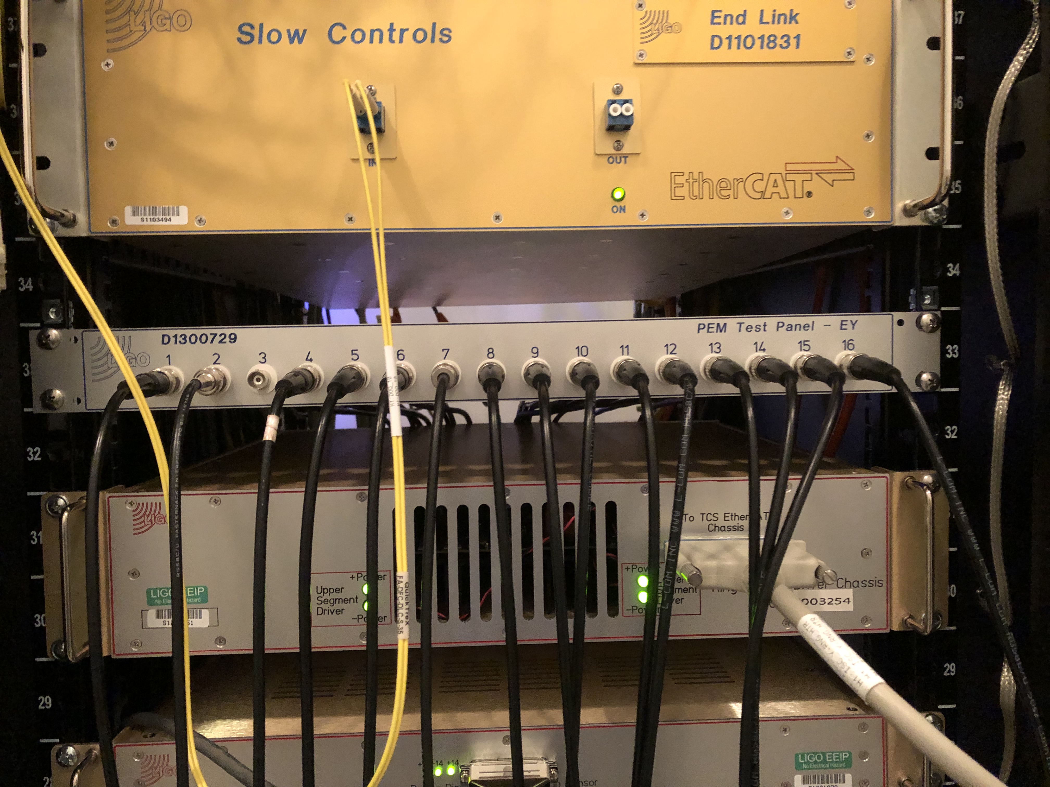
"Signals tied to the power lines through BNC bulkheads on the junction box (top of rack).
Signal routed through PEM test panel to AA chassis."
These voltage monitors are a BNC pick off from the power reduction "junction box" on the top of the end-station VEA SUS-R1 (EX/EY) field racks.
The LVLN ESD driver's power is *not* connected from the "standard" D1002189 power strips that are powering the rest of the chassis in SUS-R1.
- The dedicated / segregated power supplies live in the ante-room areas of the end-stations, in either DC power racks VDC-(X or Y)(C1 or C2). I don't have info on exactly where these live, so I can't be more specific.
The BNC monitor cables are sent to the PEM ADC via an overly complicated path:
(a) From the junction box to the 16ch BNC bulkhead PEM test patch panel (D1300779), in U41 of SUS-R1 (EX or EY)
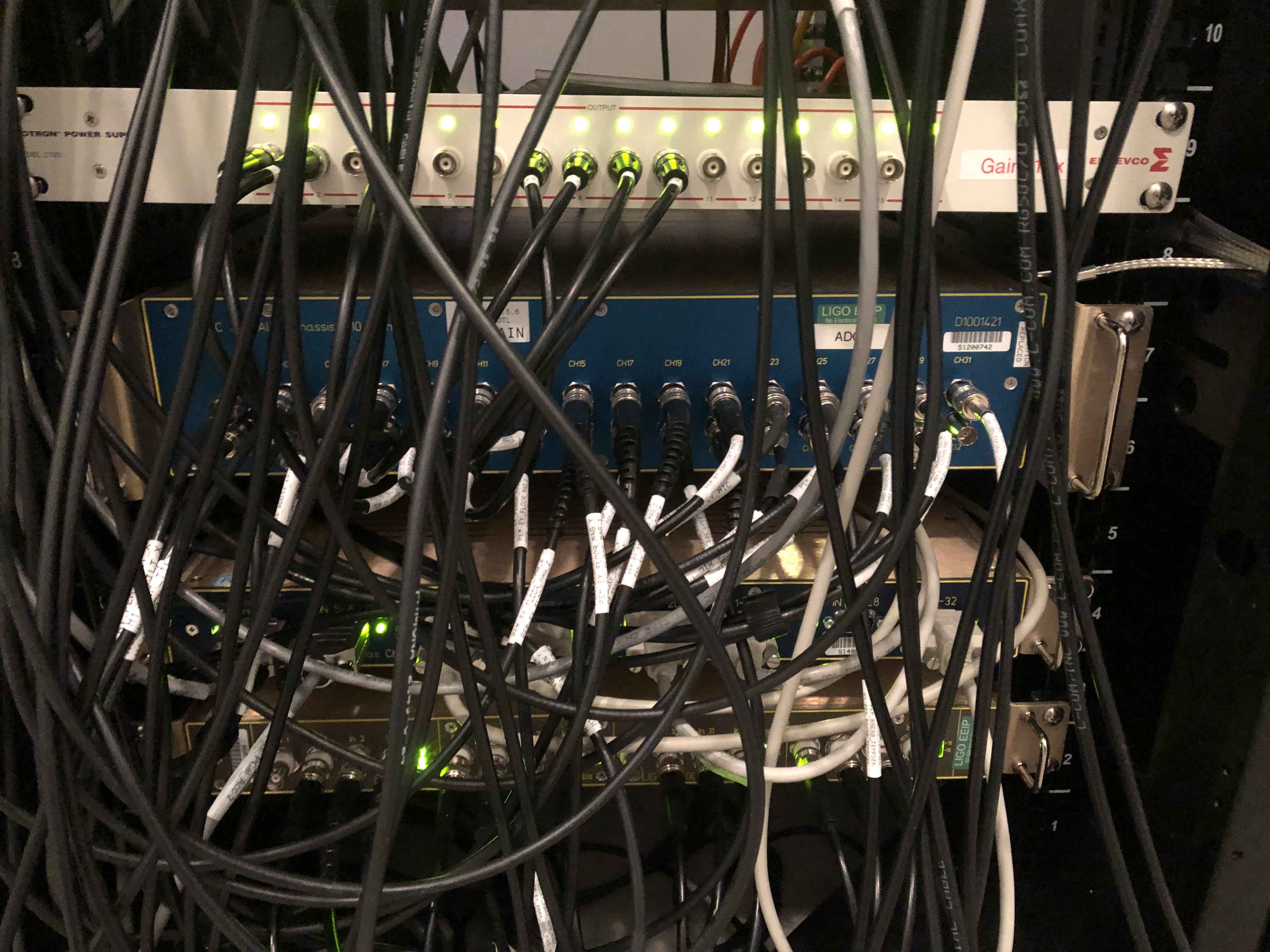
(b) That SUS-R1 patch panel is connected via a long BNC cable run to an identical patch panel at U33 of the end-station CER TCS-C1 (XC1 or YC1) racks.
(c) Then more BNCs connect the TCS-(XC1/YC1) U33 patch panel to the 32ch 10x gain PEM AA chassis, D1001421, on in to the PEM/TCS IO Chassis.
Of perhaps interesting note, it's unclear and inconsistent as to what the voltage monitor signals are monitoring. At both end stations, there're only 2 monitor channels. Fil *thinks* that these are connected to only the positive legs of each voltage. At EX, it's clear from the junction box spigot labeling that this is connected to +18V and +48V. However, at EY, the spigots are labeled +18V and -18V. This deserves clarification.
"Voltage divider boxes are installed in series."
Out of the field of view of the pictures, in between the junction box and the BNC patch panel in SUS-R1, (a), there're metal project, aka pamona, boxes wrapped in ziploc baggies. These project boxes contain a voltage divider to gain down the voltage suitable for ingestion into one of our ADCs.
"Will work with PEM group to see how we want to isolate the divider boxes and route cables.
We can do better than metal project boxes in ziploc baggies to electrically isolate them from where they rest on the rack or each other. A simple upgrade would be to just use plastic project boxes.
The idea on the table with the new cable run that Fil installed today would be to go directly from the project boxes into the AA chassis, rather than connecting through the patch panel. This has the advantage of re-freeing up the patch panel for temporary tests, and making a rather important voltage monitor more permanent.
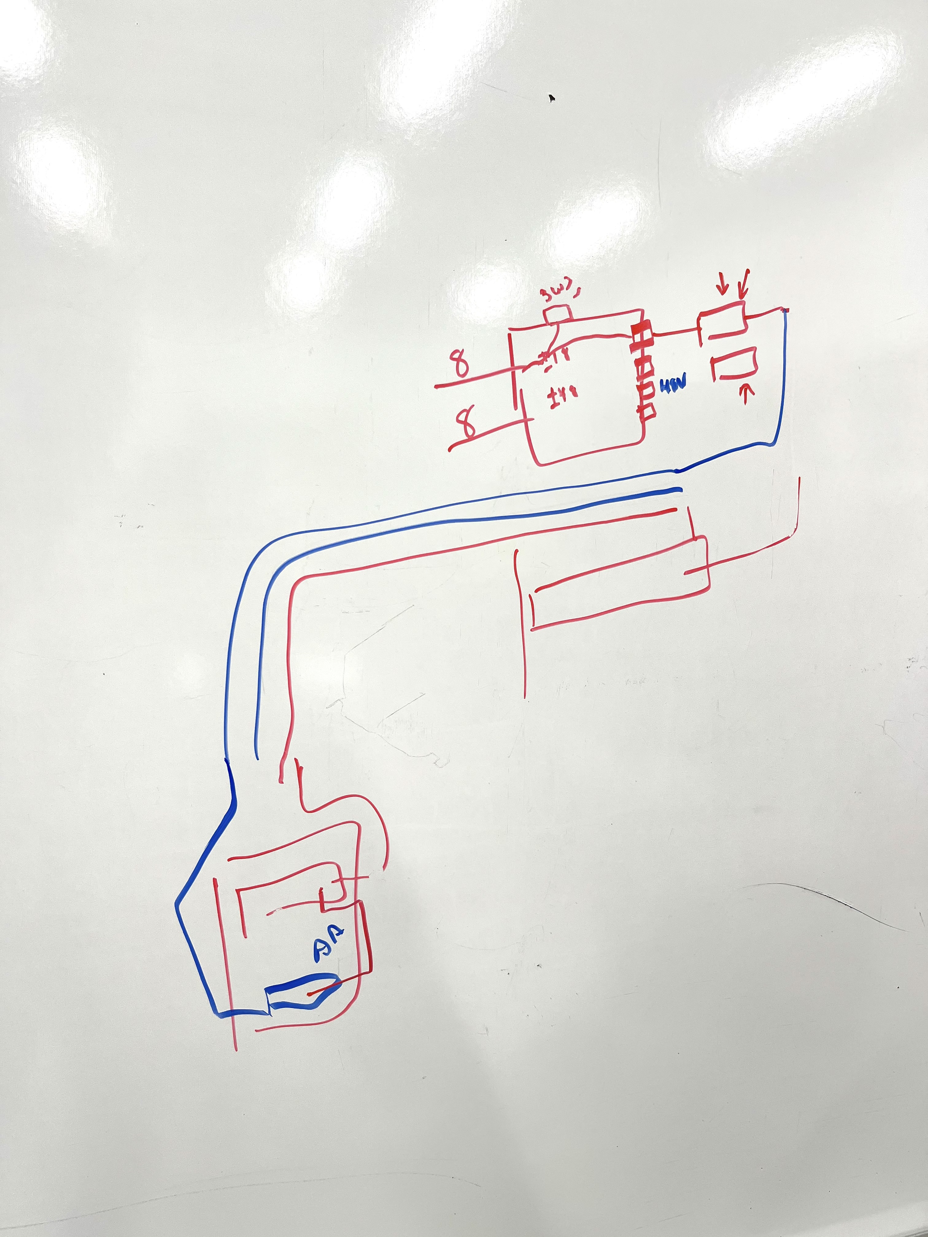
Attached are Fil's whiteboard sketch of the system -- highlighting the new long BNC cable run he pulled today between VEA SUS-R1 and CER TCS-C1 in blue.
Using Omnigraffle, the pictures Fil attaches in the main aLOG, and my knowledge of the system, I enhanced his whiteboard sketch into the attached cartoon.
Images attached to this comment
Non-image files attached to this comment
