jeffrey.kissel@LIGO.ORG - posted 16:29, Monday 11 September 2023 - last comment - 14:45, Monday 18 September 2023(72812)
Historical Systematic Error Investigations: Why MICH FF Spoiling UIM Calibration Line froze Optical Gain and Cavity Pole GDS TDCFs from 2023-07-20 to 2023-08-07
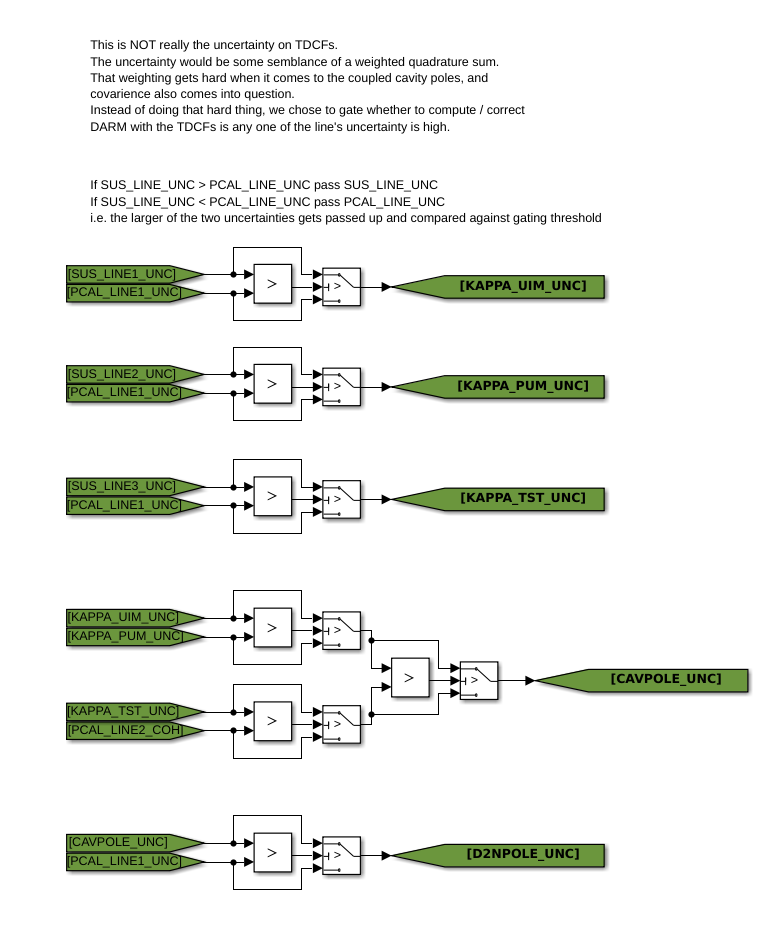
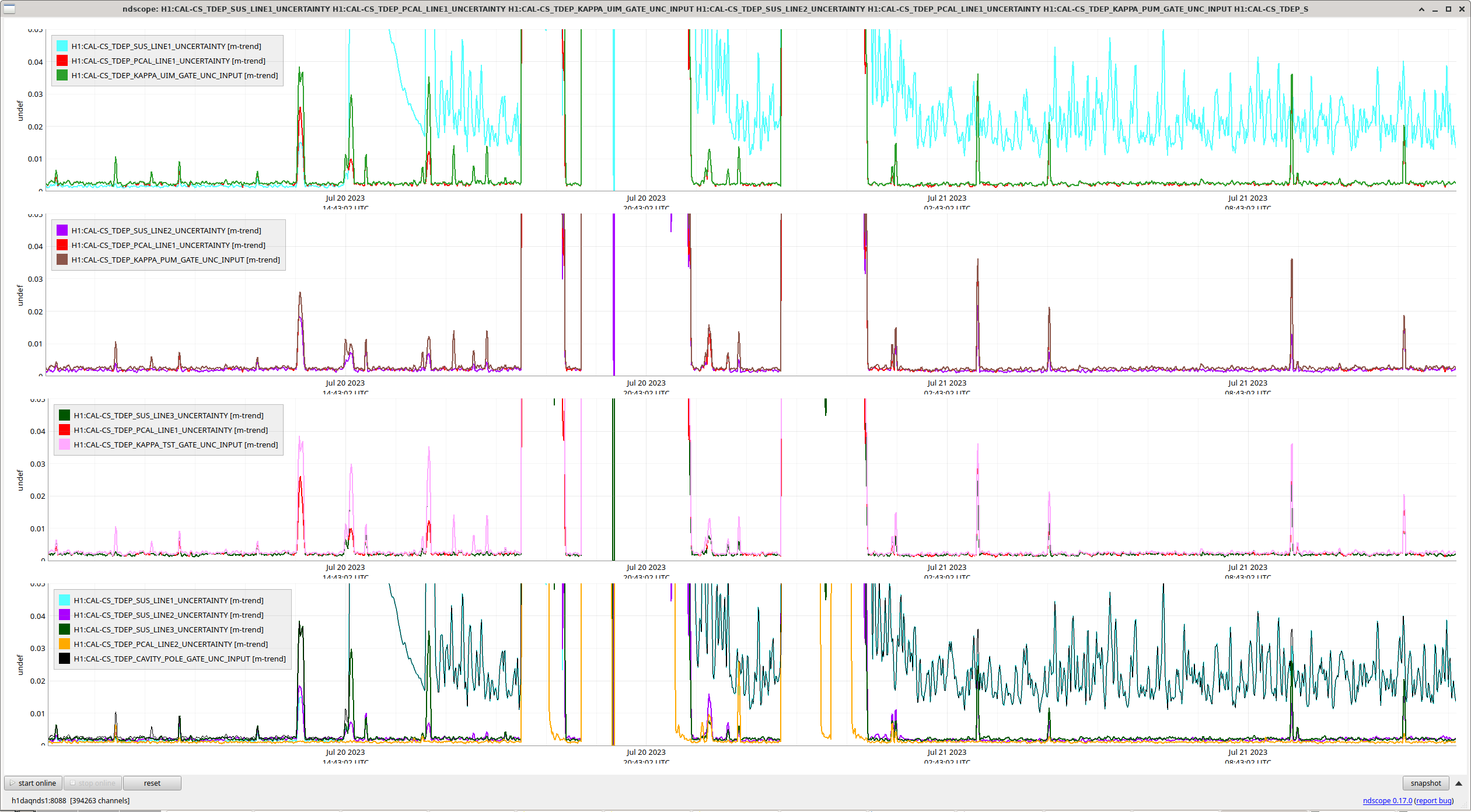
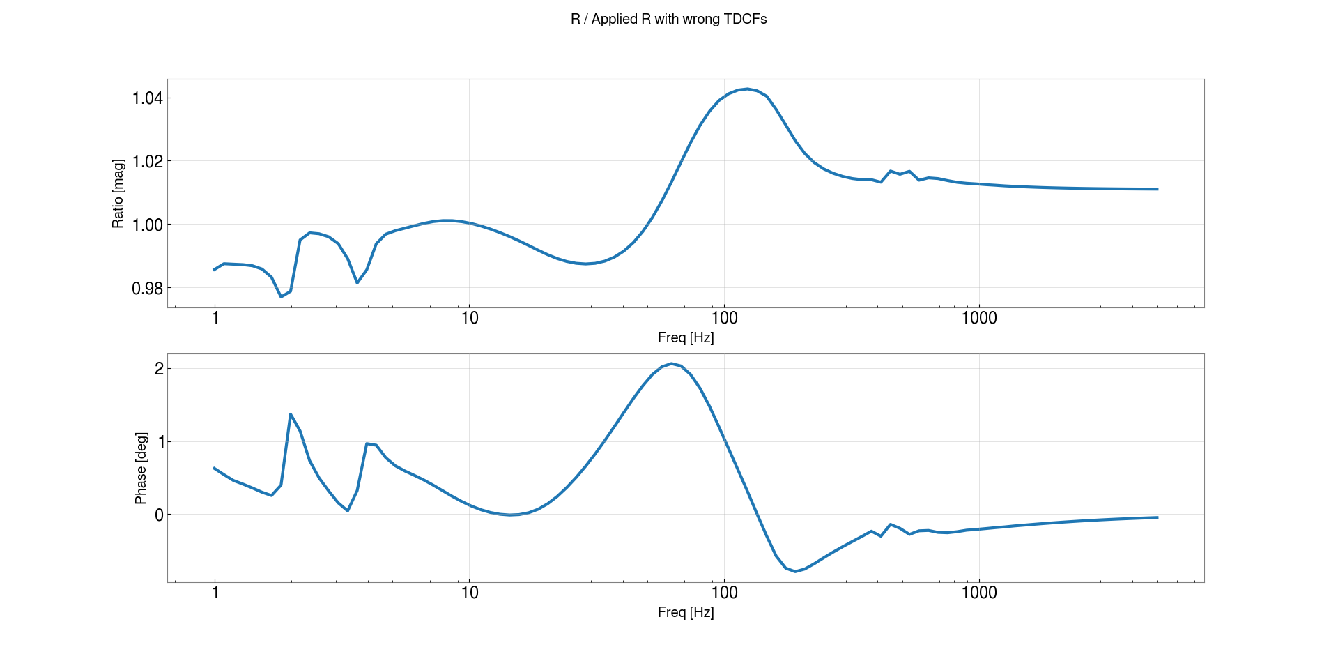
J. Kissel

I'm in a rabbit hole, and digging my way out by shaving yaks. The take-away if you find this aLOG TL;DR -- This is an expansion of the understanding of one part of multi-layer problem described in LHO:72622.

I want to pick up where I left off in modeling the detector calibration's response to thermalization except using the response function, (1+G)/C, instead of just the sensing function, C (LHO:70150).

I need to do this for when
    (a) we had thermalization lines ON during times of
    (b) PSL input power at 75W (2023-04-14 to 2023-06-21) and
    (c) PSL input power at 60W (2023-06-21 to now).

"Picking up where I left off" means using the response function as my metric of thermalization instead of the sensing function.

However, the measurement of sensing function w.r.t. to its model, C_meas / C_model, is made from the ratio of measured transfer functions (DARM_IN1/PCAL) * (DARMEXC/DARMIN2), where only the calibration of PCAL matters. The measurement response function w.r.t. its model, R_meas / R_model, on the other hand, is ''simply'' made by the transfer function of ([best calibrated product])/PCAL, where the [best calibrated product] can be whatever you like, as long as you understand the systematic error and/or extra steps you need to account for before displaying what you really want.

In most cases, the low-latency GDS pipeline product, H1:GDS-CALIB_STRAIN, is the [best calibrated product], with the least amount of systematic error in it. It corrects for the flaws in the front-end (super-Nyquist features, computational delays, etc.) and it corrects for ''known'' time dependence based on calibation-line informed, time-dependent correction factors or TDCFs (neither of which the real-time front-end product, CAL-DELTAL_EXTERNAL_DQ, does). So I want to start there, using the transfer function H1:GDS-CALIB_STRAIN / H1:CAL-DELTAL_REF_PCAL_DQ for my ([best calibrated product])/PCAL transfer function measurement.

HOWEVER, over the time periods when we had thermalization lines on, H1:GDS-CALIB_STRAIN had two major systematic errors in it itself that were *not* the thermalization. In short, those errors were:
    (1) between 2023-04-26 and 2023-08-07, we neglected to include the model of the ETMX ESD driver's 3.2 kHz pole (see LHO:72043) and
    (2) between 2023-07-20 and 2023-08-03, we installed a buggy bad MICH FF filter (LHO:71790, LHO:71937, and LHO:71946) that created excess noise as a spectral feature which polluted the 15.1 Hz, SUS-driven calibration line that's used to inform \kappa_UIM -- the time dependence of the relative actuation strength for the ETMX UIM stage. The front-end demodulates that frequency with a demod called SUS_LINE1, creating an estimate of the magnitude, phase, coherence, and uncertainty of that SUS line w.r.t. DARM_ERR.

When did we have thermalization lines on for 60W PSL input? Oh, y'know, from 2023-07-25 to 2023-08-09, exactly at the height of both of these errors. #facepalm
So -- I need to understand these systematic errors well in order to accurately remove them prior to my thermalization investigation.

Joe covers both of these flavors of error in LHO:72622.

However, after trying to digest latter problem, (2), and his aLOG, I didn't understand why spoiled \kappa_U alone had such impact -- since we know that the UIM actuation strength is quite unimpactful to the response function.

INDEED (2) is even worse than "we're not correcting for the change in UIM actuation strength -- because
    (3) Though the GDS pipeline (that finishes the calibration to form H1:GDS-CALIB_STRAIN) computes its own TDCFs from the calibration lines, GDS gates the value of its TDCFs with the front-end-, CALCS-, computed uncertainty. So, in that way, the GDS TDCFs are still influenced by the front-end, CALCS computation of TDCFs.

So -- let's walk through that for a second.
The CALCS-computed uncertainty for each TDCF is based on the coherence between the calibration lines and DARM_ERR -- but in a crude, lazy way that we thought would be good enough in 2018 -- see G1801594, page 13. I've captured a current screenshot, First Image Attachment  of the now-times simulink model to confirm the algorithm is still the same as it was prior to O3.

In short, the uncertainty for the actuator strengths, \kappa_U, \kappa_P, and \kappa_T, is created by simply taking the larger of the two calibration line transfer functions' uncertainty that go in to computing that TDCF -- SUS_LINE[1,2,3] or PCAL_LINE1.

HOWEVER -- because the optical and cavity pole, \kappa_C and f_CC, calculation depends on subtracting out the live DARM actuator (see appearance "A(f,t)" in the definition of "S(f,t)" in Eq. 17 from ), their uncertainty is crafted from the largest of the \kappa_U, \kappa_P, and \kappa_T, AND PCAL_LINE2 uncertainties. It's the same uncertainty for both \kappa_C and f_CC, since they're both derived from the magnitude and phase of the same PCAL_LINE2.

That means the large SUS_LINE1 >> \kappa_U uncertainty propagates through this "greatest of" algorithm, and also blows out the \kappa_C and f_CC uncertainty as well -- which triggered the GDS pipeline to gate its 2023-07-20 TDCF values for \kappa_U, \kappa_C, and f_CC from 2023-07-20 to 2023-08-07.

THAT means, that --for better or worse-- when \kappa_C and f_CC are influenced by thermalization for the first ~3 hours after power up, GDS did not correct for it. Thus, a third systematic error in GDS, (3).

*sigh*

OK, let's look at some plots.

My Second Image Attachment shows a trend of all the front-end computed uncertainties involved around 2023-07-20 when the bad MICH FF is installed.
    :: The first row and last row show that the UIM uncertainty -- and the CAV_POLE uncertainty (again, used for both \kappa_C )

    :: Remember GDS gates its TDCFs with a threshold of uncertainty = 0.005 (i.e. 0.5%), where the front-end gates with an uncertainty of 0.05 (i.e. 5%).

First PDF attachment shows in much more clear detail the *values* of bot the the CALCS and GDS TDCFs during a thermalization time that Joe chose in LHO:72622, 2023-07-26 01:10 UTC.

My Second PDF attachment breaks down Joe's LHO:72622 Second Image attachment in to its components:
    :: ORANGE shows the correction to the "reference time" response function with the frozen, gated, GDS-computed TDCFs, by the ratio of the "nominal" response function (as computed from the 20230621T211522Z report's pydarm_H1.ini) to that same response function, but with the optical gain, cavity pole, and actuator strengths updated with the frozen GDS TDCF values,
        \kappa_C = 0.97828    (frozen that the low, thermalized value of the OM2 HOT value reflecting the unaccounted-for change just one day prior at 2023-07-19; LHO:71484)
        f_CC = 444.4 Hz       (frozen)
        \kappa_U = 1.05196    (frozen at a large, noisy value, right after the MICH FF filter is installed)
        \kappa_P = 0.99952    (not frozen)
        \kappa_T = 1.03184    (not frozen, large at 3% because of the TST actuation strength drift)

    :: BLUE shows the correction to the "reference time" response function with the not-frozen, non-gated, CALCS-computed TDCFs, by the ratio of the "nominal" 20230621T211522Z response function to that same response function updated with the CALCS values,
        \kappa_C = 0.95820    (even lower than OM2 HOT value because this time is during thermalization)
        f_CC = 448.9 Hz       (higher because IFO mode matching and loss are better before the IFO thermalizes)
        \kappa_U = 0.98392    (arguably more accurate value, closer to the mean of a very noisy value)
        \kappa_P = 0.99763    (the same as GDS, to within noise or uncertainty)
        \kappa_T = 0.03073    (the same as GDS, to within noise or uncertainty)

    :: GREEN is a ratio of BLUE / ORANGE -- and thus a repeat of what Joe shows in his LHO:72622 Second Image attachment.

Joe was trying to motivate why (1) the missing ESD driver 3.2 kHz pole is a separable problem from (2) and (3), the bad MICH FF filter spoiling the uncertainty in \kappa_U, \kappa_C, and f_CC, so he glossed over this issue. Further what he plotted in his second attachment, and akin to my GREEN curve, is the *ratio* between corrections, not the actually corrections themselves (ORANGE and BLUE) so it kind of hid this difference.
Images attached to this report
Non-image files attached to this report

Comments related to this report
This plot was created by create_no3p2kHz_syserror.py, and the plots posted correspond to the script as it was when the Calibration/ifo project git hash was 53543b80.
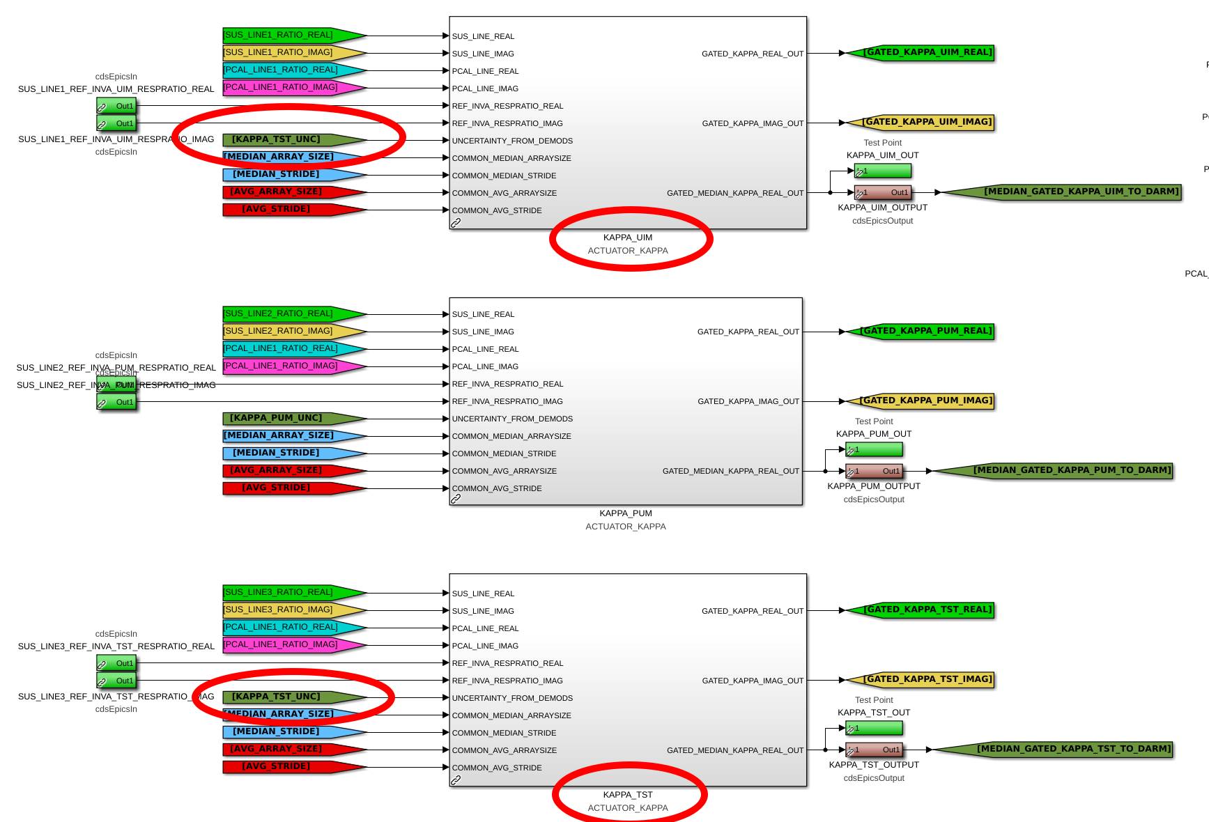
While shaving *this* yak, I found another one -- The front-end CALCS uncertainty for the \kappa_U gating algorithm incorrectly consumes \kappa_T's uncertainty.

The attached image highlights the relevant part of the
    /opt/rtcds/userapps/release/cal/common/models/
        CAL_CS_MASTER.mdl
library part, at the CS > TDEP level.

The red ovals show to what I refer. The silver KAPPA_UIM, KAPPA_PUM, and KAPPA_TST blocks -- which are each instantiations of the ACTUATOR_KAPPA block within the CAL_LINE_MONITOR_MASTER.mdl libary -- each receive the uncertainty output from the above mentioned crude, lazy algorithm (see first image from above LHO:72812) via tag. The KAPPA_UIM block incorrectly receives the KAPPA_TST_UNC tag.

The proof is seen in the first row of other image attachment from above LHO:72812 -- see that while the raw calibration line uncertainty (H1:CAL-CS_TDEP_SUS_LINE1_UNCERTAINTY) is high, the resulting "greater of the two" uncertainty (H1:CAL-CS_TDEP_KAPPA_UIM_GATE_UNC_INPUT) remains low, and matches the third row's uncertainty for \kappa_T (H1:CAL-CS_TDEP_KAPPA_TST_GATE_UNC_INPUT), the greater of H1:CAL-CS_TDEP_PCAL_LINE1_UNCERTAINTY and H1:CAL-CS_TDEP_SUS_LINE3_UNCERTAINTY.

You can that this is the case even back in 2018 on page 14 of G1801594, so this has been wrong since before O3.

*sigh*

This makes me wonder which of these uncertainties the GDS pipeline gates \kappa_U, \kappa_C, and f_CC on ...
I don't know gstlal-calibration well enough to confirm what channels are used. Clearly, from the 2023-07-26 01:10 UTC trend of GDS TDCFs, they're gated. But, is that because H1:CAL-CS_TDEP_SUS_LINE1_UNCERTAINTY is used as input all of the GDS computed \kappa_U, \kappa_C, and f_CC, or are they using H1:CAL-CS_TDEP_KAPPA_UIM_GATE_UNC_INPUT?

As such, I can't make a statement of how impactful this bug has been.

We should fix this, though.
Images attached to this comment
The UIM uncertainty bug has now been fixed and installed at H1 as of 2023-09-12 17:00 UTC. See LHO:72820 and LHO:72830, respectively.
J. Kissel, M. Wade

Following up on this:
    This makes me wonder which of these uncertainties the GDS pipeline gates \kappa_U, \kappa_C, and f_CC on [... are channels like] H1:CAL-CS_TDEP_SUS_LINE1_UNCERTAINTY used as input all of the GDS computed \kappa_U, \kappa_C, and f_CC, or are they using H1:CAL-CS_TDEP_KAPPA_UIM_GATE_UNC_INPUT?

I confirm from Maddie that
    - The channels that are used to inform the GDS pipeline's gating algorithm are defined in the gstlal configuration file, which lives in the Calibration namespace of the git.ligo.org repo, under
    git.ligo.org/Calibration/ifo/H1/gstlal_compute_strain_C00_H1.ini
where this config file was last changed on May 02 2023 with git hash 89d9917d.

    - In that file, The following config variables are defined (starting around Line 220 as of git hash version 89d9917d),
        #######################################
        # Coherence Uncertainty Channel Names #
        #######################################
        CohUncSusLine1Channel: CAL-CS_TDEP_SUS_LINE1_UNCERTAINTY
        CohUncSusLine2Channel: CAL-CS_TDEP_SUS_LINE2_UNCERTAINTY
        CohUncSusLine3Channel: CAL-CS_TDEP_SUS_LINE3_UNCERTAINTY
        CohUncPcalyLine1Channel: CAL-CS_TDEP_PCAL_LINE1_UNCERTAINTY
        CohUncPcalyLine2Channel: CAL-CS_TDEP_PCAL_LINE2_UNCERTAINTY
        CohUncPcalyLine4Channel: CAL-CS_TDEP_PCAL_LINE4_UNCERTAINTY
        CohUncDARMLine1Channel: CAL-CS_TDEP_DARM_LINE1_UNCERTAINTY
      which are compared against a threshold, also defined in that file on Line 114,
        CoherenceUncThreshold: 0.01

    Note: the threshold is 0.01 i.e. 1% -- NOT 0.005 or 0.5% as described in the body of the main aLOG.

    - Then, inside the gstlal-calibration code proper,
        git.ligo.orgCalibration/gstlal-calibration/bin/gstlal_compute_strain
    whose last change (as of this aLOG) has git hash 5a4d64ce, there are lines of code buried deep that compute create gating around lines
        :: L1366 for \kappa_T,
        :: L1425 for \kappa_P,
        :: L1473 for \kappa_U
        :: L1544 for \kappa_C
        :: L1573 for f_CC

    - From these lines one can discern what's going on, if you believe that calibration_parts.mkgate is a wrapper around gstlal's pipeparts.filters class, with method "gate" -- which links you to source code "gstlal/gst/lal/gstlal_gate.c" which actually lives under
        git.ligo.org/lscsoft/gstlal/gst/lal/gstlal_gate.c

    - I *don't* believe it (because I don't believe in my skills in following the gstlal rabbit hole), so I asked Maddie. She says:
    The code uses the uncertainty channels (as pasted below) along with a threshold specified in the config (currently 0.01, so 1% uncertainty) and replaces any computed TDCF value for which the specified uncertainty on the corresponding lines is not met with a "gap". These gaps get filled in by the last non-gap value, so the end result is that the TDCF will remain at the "last good value" until a new "good" value is computable, where "good" is defined as a value computed during a time where the specified uncertainty channels are within the required threshold.
    The code is essentially doing sequential gating [per computation cycle] which will have the same result as the front-end's "larger of the two" method.  The "gaps" that are inserted by the first gate are simply passed along by future gates, so future gates only add new gaps for any times when the uncertainty channel on that gate indicates the threshold is surpassed.  The end result [at the end of computation cycle] is a union of all of the uncertainty channel thresholds.

    - Finally, she confirms that
        :: \kappa_U uses
            . CAL-CS_TDEP_PCAL_LINE1_UNCERTAINTY,
            . CAL-CS_TDEP_SUS_LINE1_UNCERTAINTY
        :: \kappa_P uses
            . CAL-CS_TDEP_PCAL_LINE1_UNCERTAINTY,
            . CAL-CS_TDEP_SUS_LINE2_UNCERTAINTY
        :: \kappa_T uses
            . CAL-CS_TDEP_PCAL_LINE1_UNCERTAINTY,
            . CAL-CS_TDEP_SUS_LINE3_UNCERTAINTY
        :: and both \kappa_C f_CC use
            . CAL-CS_TDEP_PCAL_LINE1_UNCERTAINTY,
            . CAL-CS_TDEP_PCAL_LINE2_UNCERTAINTY,
            . CAL-CS_TDEP_SUS_LINE1_UNCERTAINTY,
            . CAL-CS_TDEP_SUS_LINE2_UNCERTAINTY,
            . CAL-CS_TDEP_SUS_LINE3_UNCERTAINTY

So, repeating all of this back to you to make sure we all understand: If any one of the channels is above the GDS pipeline's threshold of 1% (not 0.5% as described in the body of the main aLOG), then the TDCF will be gated, and "frozen" at the last time *all* of these channels were below 1%.

This corroborates and confirms the hypothesis that the GDS pipeline, although slightly different algorithmically from the front-end, would gate all three TDCFs -- \kappa_U, \kappa_C, and f_CC -- if only the UIM SUS line, CAL-CS_TDEP_SUS_LINE1_UNCERTAINTY was above threshold -- as it was from 2023-07-20 to 2023-08-07.