
REMOVE SEARCH FILTER
SEARCH AGAIN
Search criteria
Section: H2
Task: SYS
J. Kissel

This morning, I re-installed the H1SPIH23 pathfinder's photodiode and picomotor cable-table-brackets (CTBs) that had been temporarily moved to upgrade the Corner 1 H1 capacitive position sensor (see LHO:90791), and re-dressed the cabling cable clamps.

As mentioned in passing in LHO:90750 the CRS team will now consume the "spare" SPI_HAM3_004 quadrupus leg, that's J2 of the S2500513 instantiation of D2400342, which manifests as CH8 on the TCSY_C02, Controller 10, PICO G picomotor controller driven by the Corner 2 ECAT chassis -- which shows up on the H1SYSCSAUX computer's SDF system. So this has been routed in the +X direction and up in +Z to the table top on the +Y corner.

I'll post pictures of all the re-dressing in the comments so I can better caption them.
Mitchell, Disha, Robert
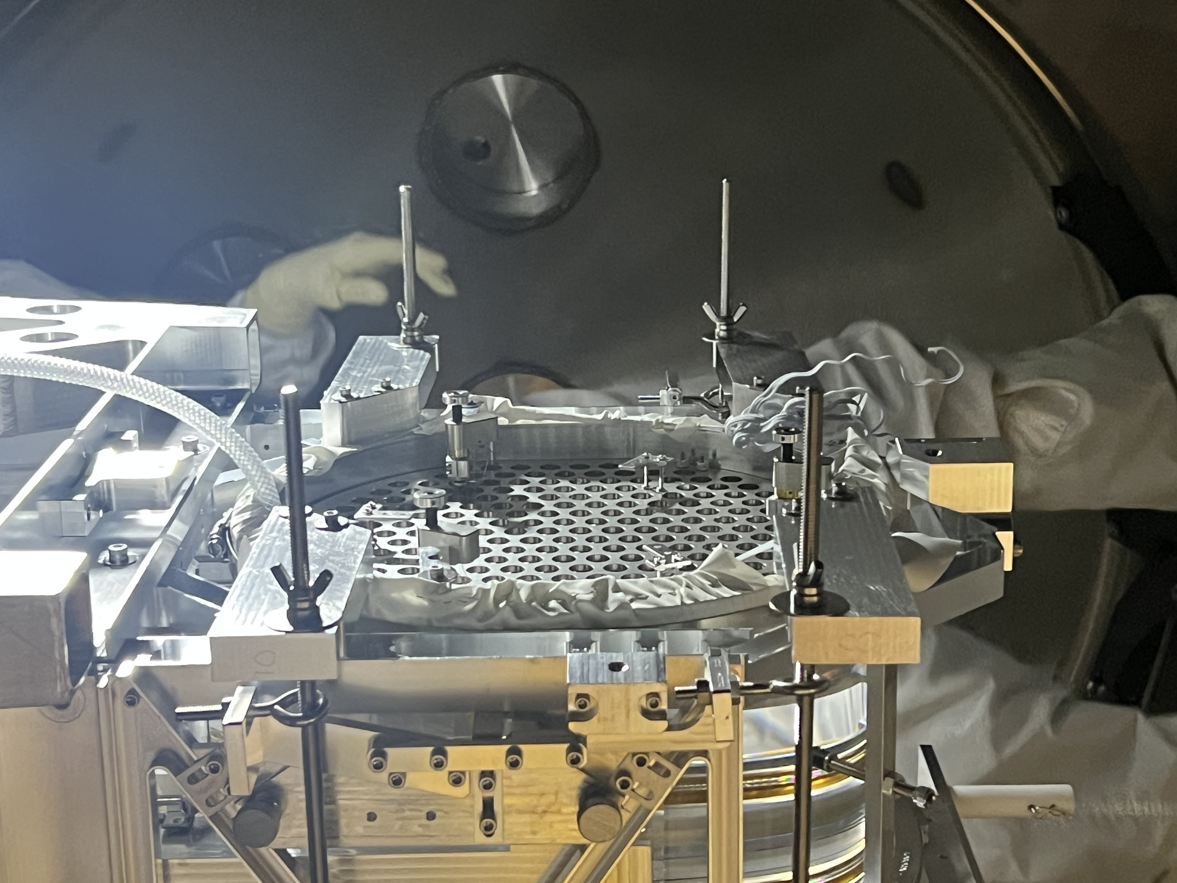
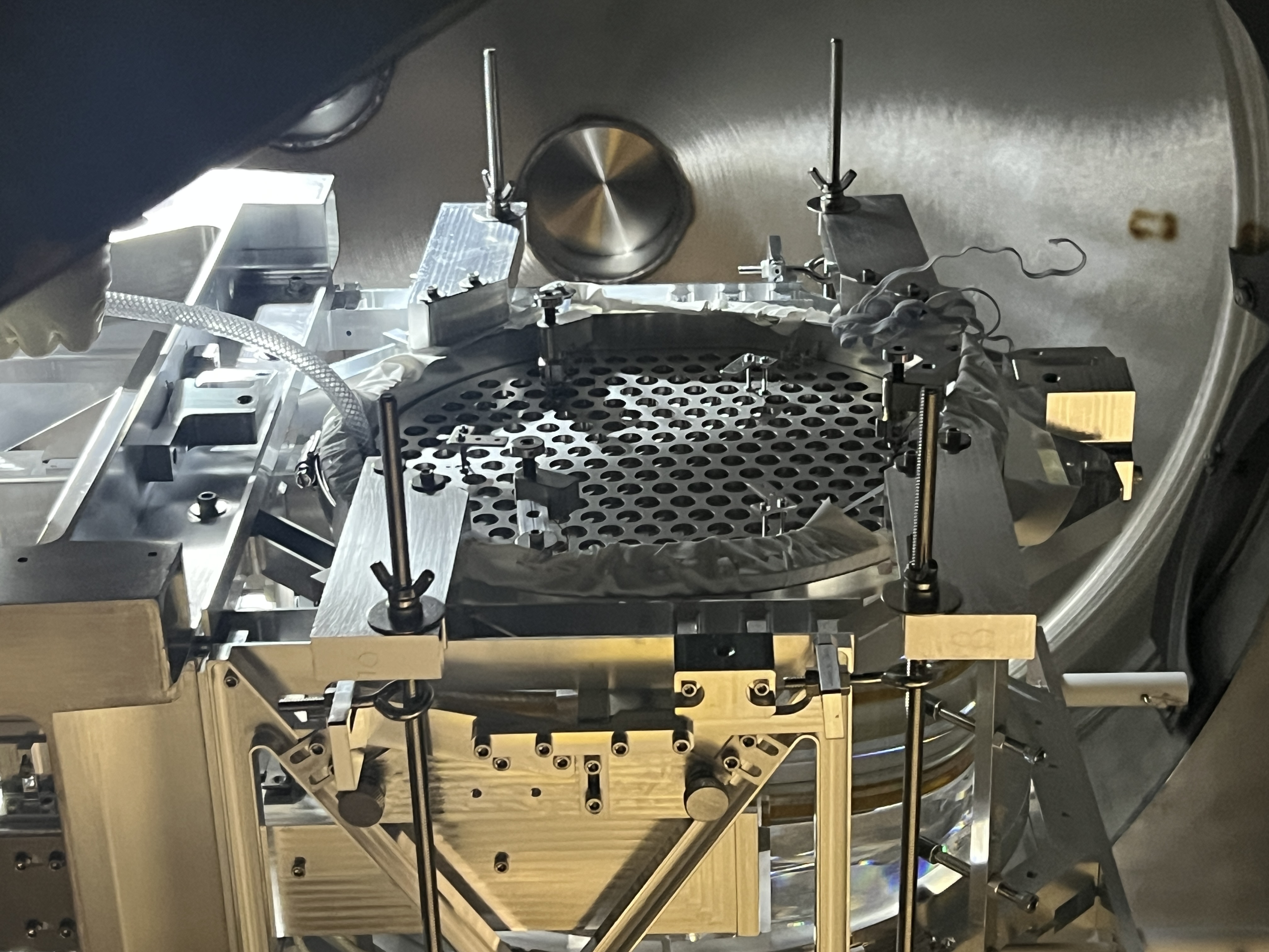
On Friday we finished alignment of the baffles on the +X side of HAM3. This took extra time because we didn’t expect 12 point flange bolts on the PR2 dog clamps that we were moving. Beam spot photos from the BBS showed that we had mitigated retroreflections from the dog clamps and other retro-reflectors that we were worried about, but the brackets for two of the SPI baffles formed strong 2-D corner reflectors with the table top (see figure). We need to hide them with something that is the same height but not normal to the BBS-PR3 beam, and we need to finish aligning the baffles on the –X side. We may also need to treat two of the table baffle brackets on the +X side of HAM3 if they produce retroreflections in PR3 beam spot photos.
Here's some pictures to aide the conversation about "which brackets are SPI bracket retro-reflectors?" These were taken on 2026-06-18 when TJ and I were installing these baffles for the first time (see LHO:90676). Two versions of each photo, one annotated and one not. 2026-06-18_H1SPIH23_ISIK_Baffles_BigPicture_ANNOTATED.jpg shows "looking in the +X direction" big-picture view of the beam splitter from inside the HAM23 mode cleaner tube, and highlights in red which baffles' brackets are the problem. 2026-06-18_H1SPIH23_MinusYSide_Baffles_TopDown_IsometricView_ANNOTATED.png shows a top-down / isometric, "looking in the +X / +Y / -Z direction" view of the -X / -Y corner of the optical table, again calling out the problematic baffle brackets. Saying it out loud -- it's not one baffle's brackets, its both - the -Y bracket of the middle upper panel baffle, and - the +Y bracket of the -Y upper panel baffle. of the ISIK shroud assembly D2400106 Also -- just saying it out loud. Robert shows how shiny these brackets are in the -X view of HAM3 from the beam splitter. "Why aren't these an issue for the -Y view of HAM4 from the beam splitter?" Because HAM4 doesn't have any of these HAM table baffles on its -Y side -- the HAM3 baffles exist because we had to remove the lower panel of the HAM2-HAM3 *mode cleaner tube* baffle on the HAM3 end of the tube (LHO:90138 and LHO:90162) in order to support SPI. But the equivalent panel on the HAM4 end of the HAM4-HAM4 tube baffle is still in place, so these HAM table baffles are not needed.


J. Kissel, J. Wright, T. Shaffer, J. Warner, J. Freed (belated aLOG covering 2026-06-22 activity) After enjoying a lovely long, Juneteeth Holiday weekend, TJ and I wrapped up the few loose ends that were left after the 2026-06-18 super push to get everything installed (see last update; LHO:90676). - As a fall out of LHO:90667, Jim, Arnaud and I discussed the pros and cons of using the current, D1000907-v7, balance mass "Payload & Suspended Mass Assembly" arrangement in regards to the W9 corner. We concluded that leaving the D1000907-v4 configuration for this corner in place -- i.e. having 11.6 [kg] of mass in small, modular, optional components -- was better that having one "giant" 10 [kg] mass in "the same" location (on the table top, but in the same W9 corner). As such, we left the plates as re-installed on LHO:90713, with the acknowledgement that the final configuration to create a balanced ISI may be different even further than D1000907-v7. - Using a beam profiler, we measured the Beam Profile of the beam returning from M_C1 on the HAM23 ISIJ Reflector. This is to, at least roughly, confirm the radii of curvature of the M_C1 mirror. We expected a 2 [mm] diameter beam, and we got a 2 [mm] beam diameter. A more thorough aLOG to come. - We did NOT address the stray beam that Jennie mentions in her summary -- yet. I'll also write a separate aLOG on this, but in short -- it's a ~0.2 [mW] beam that's what ~18% reflection there is off of a silicon diode, and it hits the -X/-Z rim of the chamber of the +Y door, and the (splotchy) spot size is ~4-5 [mm] in diameter. The SPI team has been aware of this beam since testing in the optics lab (see mention of it, e.g. in LHO:90455), but hoped that it would land on some part of the SPI Shroud assembly, but it *just* misses it. With this last item, we consider the Installation and Integrated Test Plan COMPLETE (T2500024) ... to as good as possible with the HAM3 ISI still locked. And that ... qualifier is a "just in case" qualifier, as it's a "we'll see what happens" when the ISI gets unlocked, and we've got an excellent amount of remote adjustability to be able to recover the MEAS IFO's alignment if HAM3 moves a lot between - "locked," - "re-balanced and damped" and - "isolated with feedback and DC positioning engaged." Essentially, we've launched the SPI pathfinder into space, and now its up to out built-in remote controlled actuators and sensors to take us home to achieve our scientific goals (see T2600019). Super congrats to all, and similarly large thank you. We did a thing!


J. Oberling, R. Crouch, J. Warner, B. Weaver, I. Abouelfettouh, O. Patane, S. Appert
And finally, here is the long-promised alog for our full set of measurements of the now-deinstalled aLIGO BS. I will give a brief overview of the WBSC2 support tube and BS in-chamber measurements we took, but the bulk of this alog will concern the various test stand measurements we took and how they tie in to the in-chamber and support tube measurements. As a reminder, our alignment tolerances for the aLIGO BS were:
Strap in folks, this is going to be a long one with a wall of text. But first, I demand... A shrub, errr, a summary!
Summary
Earlier this year we measured the location of the ends of the WBSC2 support tubes. They indicated a -X translation of the WBSC2 cartridge and a CCW yaw. But, since the support tube length wasn't a controlled dimension for support tube construction we can't use them to definitively inform us about the cartridge assembly in the chamber (we've measure 4 tubes so far, and all 4 have been different lengths by several mm). The -X translation was a little surprising because we translated the cartridge in the +X direction during our 2013 install, implying that the support tubes were already sitting too far in the -X direction. The CCW yaw wasn't surprising since we yawed the cartridge CCW back in 2013.
At first we thought the in-chamber alignment looked pretty good, it was only after the cartridge had been removed from the chamber that we realized the mode we had used to make the measurements had a high potential to disguise positional deviations and make the measured point look closer to nominal than it actually was (see the in-chamber section below for full details). The decision to use this mode was made during our planning for the alignment (it's in our alignment procedure), and was based on an incomplete understanding of how the underlying mode actually worked. Well, now we know better, but unfortunately the consequence is that we cannot say how well the BS was aligned to the IFO XYZ coordinate system. What we can say is that the BS was clearly yawed in the CW direction w.r.t. the SUS cage, by potentially several mrad, but have no insight into how it was yawed w.r.t. the IFO XYZ axes.
On the test stand, we found the BS SUS to be right on the edge of our position tolerances for the optic. We never measured the SUS cage back in 2013, so this was the first time we had looked at it. The optic itself was found to be within our position specs, but we did measure the position to be in a different place than we did in 2013. We traced this primarily to 2 things: The large +/- 2.0 mm error bar in the total station's distance measurement mode (used to set the optic's longitudinal position in 2013) and errors in the position of the test stand's brass monuments (used to place the alignment equipment in 2013). We were able to trace this using the FARO, using its much higher accuracy to measure both the BS longitudinal position and the test stand monuments. We did find that the pointing of the BS was well outside of our specs: pitch was ~200 µrad up while yaw was ~710 µrad CW. While the pitch being out of spec after the cartridge was craned was not surprising (looking back through my aLIGO install notes we never had a pitch alignment survive craning into a chamber), we were surprised at the yaw measurement. The mispositioning of the test stand monuments did not explain this yaw, and we could find no obvious cause.
WBSC2 Support Tubes
The WBSC2 support tube ends were surveyed with FARO earlier this year. From talks with Jim, my understanding is that support tube length was not a critical dimension for tube construction, and so far this is holding up. We've measured the support tube ends for WBSC2 and WBSC3 so far (more to come as we're able), and the lengths have not been constant (the WBSC3 support tubes measured short of their design length, and each one was a different length, while both WBSC2 support tubes measured longer than their design length). Because of this, we can't give any definitive numbers about the respective cartridges, but the info does offer some general guidance. For WBSC2 this is:
The important thing to note here, in my opinion, is the CCW yaw (again, the direction, not so much the exact number). This will be important later on, once we get to the test stand measurements.
aLIGO BS In-Chamber
We took a series of measurements on the BS while in the chamber in mid-April, see the alog for more detail. Some important takeaways, in my opinion:
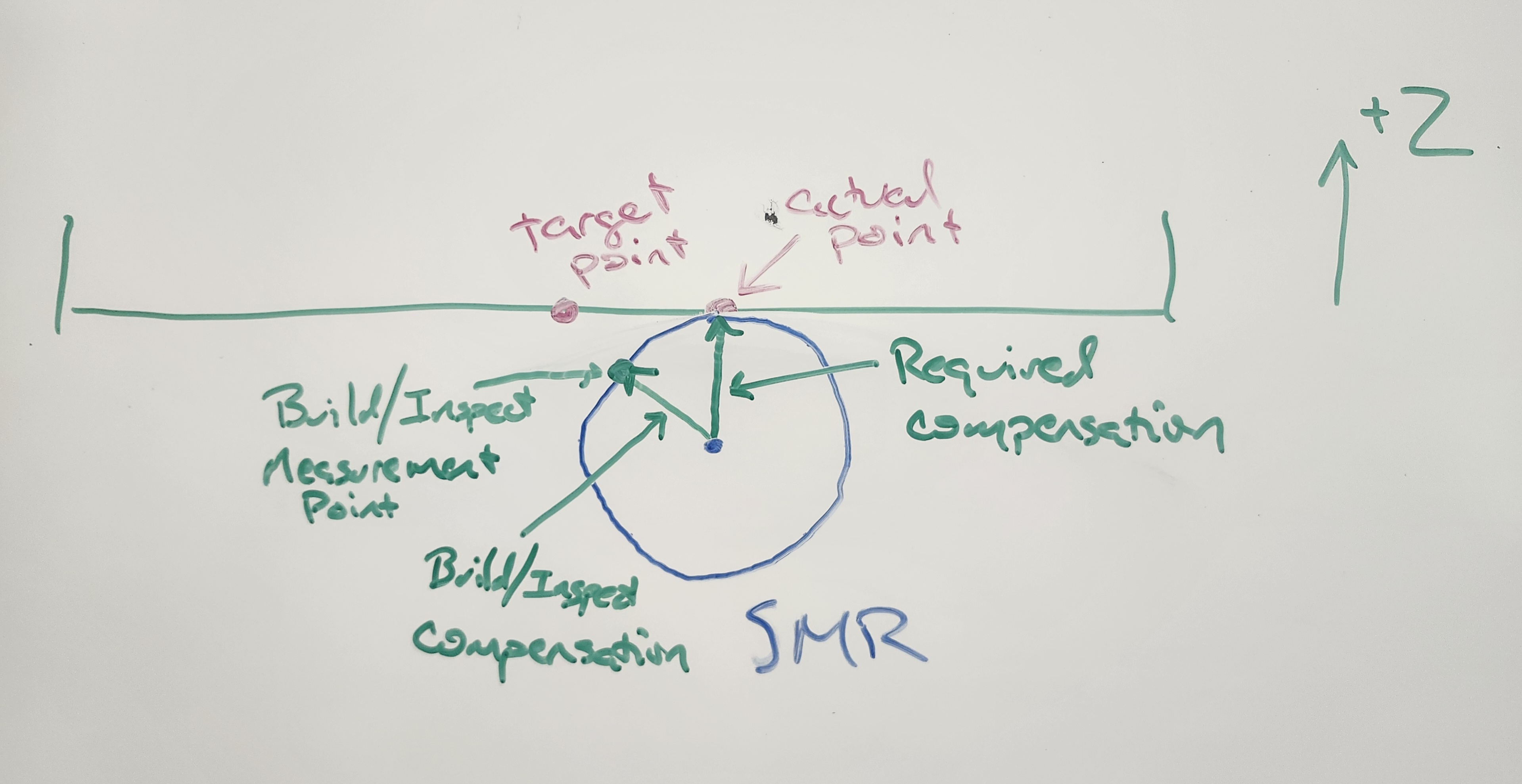
Because we used the Build/Inspect mode with the automatic SMR radius compensation turned ON to measure the BS SUS position in-chamber, we unfortunately do not have a good idea of where the SUS was located within WBSC2 and by extension do not have a good idea of where the BS optic was positioned. Subsequent testing after the cartridge had been removed from the chamber showed that we did not have a good understanding of how the automatic SMR compensation worked. Short version: It's dumb. It simply compensates in the direction of the measurement object, regardless of where your measured point is. For example, you're measuring a point on the the underside of a horizontal plate with Build/Inspect mode. The SMR would sit below this plate in the -Z direction, so the SMR radius should be compensated in the +Z direction. The automatic compensation does not compensate in the +Z axis alone, it compensates directly towards the nominal point. This then can result in a measurement that looks dead on but in fact could be nowhere close; if the actual point is off several mm in the X and Y directions, the automatic compensation would make the resulting measurement look like it was dead on as it compensates towards the measurement object, removing the actual deviations in the process. The final attached picture is a drawing showing this behavior. We finally noticed this while testing the FARO test stand alignment procedure on an old HAM passive stack after the BS cartridge was removed, and then confirmed it while aligning the BBS SUS on the test stand; initial BBSS placement was done via Build/Inspect as a real time feedback, but we measured the points using a more involved method that tells PolyWorks what direction to compensate in instead of letting the software do it automatically. The measured points were several mm off of the Build/Inpsect points, and we confirmed the automatic compensation was the cause by turning it on and off (when automatic compensation was turned off, Build/Inspect reported deviations that matched our direct measurement of the alignment points).
aLIGO BS Test Stand
FARO Measurements
And now we come to the test stand meausurements. To start, we aligned the FARO to the ISI using 10 points on the ISI; these points and the resulting alignment are shown in the 1st attached picture, and show the FARO is well aligned to the ISI. Once the FARO was aligned to the ISI we then measured several points along the bottom of the SUS cage, as well as the center of both the HR and AR sides of the lower Figure 8 structure; this is shown in the 2nd attached picture. We did not measure the SUS cage position during aLIGO install, only the optic position, so it's good to see the cage is mostly in the neighborhood of the optic position tolerances. One note about the Z axis numbers shown here: The CAD model used here is the in-chamber model, which places the BS at its in-chamber Z axis coordinate of -82.9 mm. However, the BS SUS is the same length as the QUAD SUSs, so the BS is placed w.r.t. the ISI the same as the QUADs, i.e. at -80.0 mm; -82.9 mm was acheived in-chamber by lowering HEPI, but on the test stand the BS was aligned at -80.0 mm. This was never properly corrected for in the CAD model; I think the SUS cage itself and its components were lowered while the ISI was left at its nominal height, so all the Z axis measurements should show a deviation of around +2.9 mm (since they are physically higher than the CAD would indicate). This is seen most clearly with the HR and AR Figure 8 structure measurements. Both Z axis positions measured right around -80.0 mm as they should, while the CAD model claims they are too high. This has been corrected for in the BBS CAD model, so this is the only time we'll see this discrepancy.
The 3rd attached picture shows a set of lines created from the measurement points we took on the structure which show how the BS SUS cage is rotated w.r.t. the ISI; I also rotated the CAD model so that it matches the target yaw angle of the BS optic itself. The angles here are reported w.r.t. their respective positive axes (i.e. X Ang is the angle measured from the positive X axis). As can be seen, the SUS cage had a large CCW yaw w.r.t. the ISI. Averaging the various yaw deviations gives a yaw of the BS SUS w.r.t. the ISI of 0.2762°, or 4.82 mrad CCW. This explains the large CW yaw of the BS optic w.r.t. the SUS cage.
With those measurements done we then used the FARO to set a total station looking at the AR surface of the BS, set along the target AR surface normal so we can measure position deviations from nominal. Once we had these position deviations we moved the total station to the HR side of the BS, mounted a laser autocollimator (LAC) on top of it, set it along the target HR surface normal and offset by 150.0 mm (to avoid the test stand leg) to measure the pitch and yaw of the BS. The results were posted to the alog here, so the details follow below.
I should note here how we measured the longitudinal position of the BS AR surface. As noted above, we used the FARO to measure the circle that represents the AR side of the lower Figure 8 structure of the BS SUS; PolyWorks calculates the center of this circle, and is what is shown on the 2nd attachement with the label "BS_FIG8_AR". We also know the position of the total station, as we set that using the FARO. We then use PolyWorks to measure the distance between the total station and the BS AR Figure 8, as well as measure the target distance from the total station to the BS AR surface. We then measure the distance from the AR Figure 8 to the BS AR surface using a depth micrometer; this was done on the left, right, top and bottom of the Figure 8. These 4 measurements are averaged together to give us a distance from the Figure 8 to the BS AR surface, which is then added to the measured distance from the total station to the AR Figure 8. This final distance is compared to the target "total station to BS AR" distance to give us the longitudinal position deviation of the BS AR surface.
BS Position and Pointing
The original BS test stand alignment was completed in early February 2013. The below table gives the final position and pointing deviations we measured in 2013 and those we measured now; I've rotated the position deviations to the IFO XYZ axes for both. In 2013 we were on Test Stand #2 (currently disassembled due to filter cavity interference) and using pre-set brass monuments, and now we are on Test Stand #1 and using the FARO to precisely set the total station.
| 2013 Test Stand | 2026 Test Stand | Difference | |
| X | +0.1 mm | -1.8 mm | -1.9 mm |
| Y | +0.1 mm | +0.8 mm | +0.7 mm |
| Z | +0.3 mm | -0.8 mm | -1.1 mm |
| Pitch | -20 µrad (up) | -200 µrad (up) | -180 µrad |
| Yaw | -10 µrad (CW) | -710 µrad (CW) | -700 µrad |
That's, uh, quite the difference, yeah? A couple of things that should be noted here:
Despite the large difference in position deviations between 2013 and 2026, these are still within our set position specification. The pointing is decidedly not. While it's entirely possible that things have drifted in the 13 years since the BS was installed, there are 2 somewhat obvious things that would contribute to this difference: The total station's +/- 2.0 mm error bar for distance measurements and error in the placement of the test stand's brass monuments. We've already measured a difference in longitudinal position between 2013 and 2026 that is within the error bar of the total station's distance measurement, but what about the test stand monuments? Well, we used FARO to measure those.
Test Stand #2 Monuments
To measure the test stand monuments we first had to align the FARO to the test stand coordinate system. To do this, we used the set of monuments set along the XY axes of the stand and PolyWorks' Best-Fit Alignment routine (the same routine used to align the FARO to the ISI on the test stand); the test stand coordinate system was assumed to be flat along the floor and 2 dimensional (XY only), so I forced all of the Z axis nominals and measured to 0.0. The results of the alignment are shown in the 4th attachment. It's immediately apparent that our test stand monuments are not going to be where we thought they were, as the alignment routine was not able to fit a good alignment between the nominal and measured coordinates of the alignment monuments (the first attachment shows the results of the alignment routine when it can find a good fit between the nominal and measured data). We re-did this a couple times and got very similar results each time (to <0.1 mm), so the monuments are definitely not where we thought they were. We proceeded to use this alignment to measure the rest of the test stand monuments; those are shown in the 5th attachment. As expected, none of the monuments are well positioned, all show large errors. Well then. So now we have both an error in the longitudinal measurement (but within the error bar) and test stand monuments not where we thought they were. How could this have affected the 2013 BS XY alignment? To figure this out, I used PolyWorks to recreate our 2013 alignment setup, now with our mispositioned monuments and with our longitudinal position error. Since we had to rotate the cartridge to place it on the test stand, I created a new coordinate system that's rotated 90° CW, so the monuments are in the same coordinates as the BS would be once installed in-chamber (I was getting cross-eyed constantly flipping between the IFO and test stand coordinate systems, this made things much easier).
First I wanted to consider how these issues could have affected our 2013 XY position alignment, so I recreated the setup looking at the AR side of the BS. The 6th attachment shows this. There's a lot of info in this picture, so match the below numbered list with the red numbers in the picture. Also, "Theo" is my shorthand for theodolite, which is another name for a total station.
That's all well and good for X and Y, but what about the Z axis deviation between 2013 and 2026? Again, all I have to fall back on is 2013 equipment setup errors or things drifting over the course of the last 13 years. For equipment setup, we set optic height by setting the total station at a target distance down from the ISI, using a scale attached to a fixed-length rod, that matched the desired Z axis position of the BS. There could have been an issue with the scale/rod setup (such as a mistake in rod length (not likely) or the scale not mounted properly) or an issue with the total station setup (such as not well levelled or sighting the scale along a zenith angle other than 90°). While I'd like to think that 2013 me would not have made such obvious mistakes, 2026 me doesn't have perfect recall of events from over a decade ago so I cannot say for sure.
For pointing I made our HR test stand setup in PolyWorks, this is shown in the 7th attachment. This is much simpler as I'm only looking to see if the monument misposition caused a large yaw error back in 2013. Quick explanation, we set our total station/LAC combo over monument TS2-20 and sighted monument TS2-19 to set our 0° reference line. We then turned 44.9711° so we were sighting parallel to the HR surface normal of the BS; the gap between the 2 lines in the picture was handled by a Lateral Hollow Transfer Periscope, a device that horizontally translates the beam by ~400 mm while keeping the output beam parallel to the input beam by 1 arcsecond (0.0003°). For a 710 µrad CW yaw deviation in the BS to be caused by the monument mispositioning the deviation of the 0 Reference Line would have to be 0.0407° in the CW direction; this would be a measured X Angle of the line "Theodolite HR HA Ref" of 90.0407°. Clearly, this is not the case. In fact, the angle deviation caused by the monument misposition is only 0.0019°, or ~33 µrad, in the CCW direction. At this point, the only explanation I have for the difference in yaw between 2013 and 2026 is an equipment setup error in 2013 or things subtly shifting in the last 13 years. Keep in mind, we're not talking large shifts in the BS to cause this yaw. If we hold one side of the BS fixed in position and then yaw it by 710 µrad, the opposite side only moves by 0.26 mm (0.000710 * 370.0 = 0.263).
Wrapping Up
So, what does this all mean? Well, with the mistake in using the Build/Inspect automatic compensation mode we don't have any better of an idea where the BS was in the IFO XYZ coordinate system than we did before the cartridge was disassembled. The measurement looks good, but as I explained above I do not trust it. The support tube measurement indicates a -X shift from nominal and a CCW yaw, but these aren't good metrics since support tube length wasn't a critical dimension during tube construction (we've measured 4 so far and all 4 have been different by several mm). I wish I had better news to report here, but we didn't notice the mistake until after the cartridge had been removed from the WBSC2 chamber so there was no way to remeasure the in-chamber position.
The test stand measurements show that the BS SUS was on the edge of our positional tolerance for the optic, with a few points just outside of it. The optic itself, the object of primary importance and the only thing we actually measured in 2013, was within our positional tolerances but different from our 2013 measurements. The primary causes of this were found to be errors in the positions of the test stand brass monuments that we used to set our alignment equipment during the intial 2013 alignment, and the large error bar in the total station's distance measurement mode. The pointing was found to be well outside our tolerances, and I currently cannot explain the yaw deviation. Looking back through my old install notes we never had our test stand pitch alignment survive being craned into the chamber (ITMx shifted by over 2 mrad in pitch after being craned into the WBSC3 chamber), so the pitch being off wasn't really surprising. But the yaw was. Our measurements of the test stand monuments, despite the position deviations, did not show a large yaw deviation. The angle we turned the total station to measure the yaw was different between our 2013 alignment and 2026 measurements, but only by ~24 µrad so not enough to account for the 710 µrad CCW yaw we measured in 2026. We couldn't find any obvious cause of this, so all I can offer are guesses (procedure mistake, equipment setup mistake, small drifts over 13 years, etc.).


J. Kissel, J. Warner During SPI install we removed the following side-wall balance mass from the W9 side wall (see first bullet of LHO:90558): Plate Mass [lbs.] Mass [kg] QTY Total Mass [kg] D071200 Type 04 7.9 3.583 3 10.750 D071200 Type 01 1.1 0.499 1 0.499 D071200 Type 00 0.6 0.272 1 0.272 D071201 0.1 0.045 3 0.136 Total Mass 11.657 First attachment is a diagram to convey which side wall I'm talking about. This is inaccurate with the latest version of the ballast / balance mass inventory, D1000907-v7, which states that this side wall has only 1x Type 04 (3.583 [kg]) and a 1x Type 03 (2.041 [kg]), for a total of 5.625 [kg]; much less. Remember, from LHO:90504 that the total SPI mass is 12.599 [kg]. This *excludes* the mass of the lower ISI Shroud baffle (D2400106-v4) and the three upper HAM Table Baffles (D2600007) with all their bracketry and bolts, currently only represented only in e-drawings posted to D2400103-v6. After talking with Jim, he wants more mass in this -X / +Y corner of the table, because that's where all the new stuff is. So he wants this corner "over" or "heavy" (because the new stuff must be in a fixed position) so that he can adjust the *opposite* corner of ballast mass (which has more open table and side wall access and thus is adjustable). As such, he says "put all the at 11.657 [kg] back on the corner. So we will! Second attachment is a picture of the wall mass arrangement prior to us removing it taken on 2026-06-09.


Masses were re-installed as of 2026-06-18! See LHO:90713.
R. Crouch, J. Warner, J. Oberling, M. Robinson
We made some more HEPI moves today to better position the BBS SUS cage. The results are shown in the 1st attachment. The deviations listed in the attachment are the deviations from nominal, but that is not our target here. To better position the BBS optic we are trying to match our position and yaw from the test stand. As a reminder, I've attached the final SUS cage alignment from the test stand (2nd and 3rd attachments). The table below shows our current deviations from the test stand alignment (all units in mm):
| SUS Alignment Points | Target from Test Stand | Actual In-Chamber | Deviation | |
| +X/+Y | X | -110.809 | -111.450 | -0.641 |
| Y | 113.819 | 113.392 | -0.427 | |
| Z | 122.562 | 122.801 | 0.239 | |
| -X/+Y | X | -499.759 | -500.327 | -0.568 |
| Y | -275.102 | -275.519 | -0.417 | |
| Z | 122.669 | 122.660 | -0.009 | |
| -X/-Y | X | -252.295 | -252.875 | -0.580 |
| Y | -522.581 | -523.013 | -0.432 | |
| Z | 122.616 | 122.811 | 0.195 | |
We wanted to bias to the negative by ~0.3 mm in both X and Y since our BBS test stand alignment had a +0.3 mm deviation in both X and Y position, so this looks pretty good. The Z axis indicates a potential off level in the cartridge assembly, but one has to be very careful in assessing level based on these measurements. These measurements are all done in the LHO Global coordinate system, which is tilted w.r.t. the local level in the WBSC2 chamber (see T0900340), so you cannot level to global coordinates; if one did then the suspension would then hang weird as it doesn't care about our different coordinate systems, it just hangs along the local gravity vector. Jim is planning on using an autolevel to measure the top of the keel mass of the ISI's Stage 2 to see how that looks (similar to what LLO did).
In addition, the yaw of the SUS cage also closely matches our test stand alignment. Our target, from the 3rd attachment, is 44.9979° from the +X axis and we are currently measuring 45.0025°. This is a difference of 0.0046°, or ~80 µrad, in the CCW direction, so pretty close to our target. We won't know for sure how good the pointing alignment is until we can use the BBS OpLev, which is not currently available (the channels do not yet exist, per Oli the plan is to add them next week), but my hope from today's work is that we'll be pretty close.
So next steps are to have the BBS OpLev available so we can assess our pointing alignment and the attachment of the HEPI actuators. We'll have to measure position again after the HEPI actuators are attached, so we aren't quite done yet.


Ibrahim, RyanS, Betsy, Corey, Anamaria
Today we pulled the forst contact fabric from ITMY.
First we de-installed the jig around the cage, leaving only the fabric still attached to the HR of the test mass. We used the top gun to blow away particulate on the sides of the quad, the CP and in between as much as we could before pulling the FC. We note that there are still small, albeit sparse, visible "dot" particulate on these surfaces. These were observed at LLO as well, so nothing too surprising.
The first contact came off nicely, as an even layer. There were two spots at the edge, about 1-1.5 inch from 10 o'clock and 2 o'clock that left some residue so we painted those two little spots to remove it. We did it twice because the first time we left a bit of a line at the edge, but that was more petty than necessary. There was a small hair-like piece, 2mm long, that didn't come off with the top gun so we used a dry cotton swab to swipe it off.
We replaced the face EQ stops and the cage baffles. The quad is locked and the ACB is still wedged up.
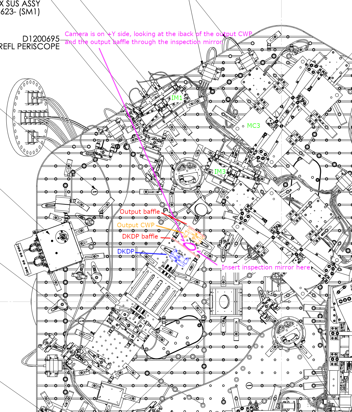
We tried to diagnose the scattering or clipping or whatever that is visible inside the IFI output baffle aperture (alog 90536, especiall this video from that alog). It's not subtle, is always there even when the beam is blocked between PRM and IM4, and it's not just once in a while, it looks to be as frequent as strong flashes from IMC.
This is not the clipping of the forward propagating beam on the baffle as the beam height is pretty good (beamheight_dkdp_baffle.mp4) and YAW is also OK on dkdp baffle as well as IFI output baffle (dkdp_baffle_yaw.mp4, IFI_output_yaw.mp4).
We took a video of the back (i.e. -Y) side of the IFI output baffle through the output CWP by inserting a big dentist mirror between DKDP baffle and CWP and shooting from the +Y side. Video will be posted later (the raw video from IR sensitive camera exceeds 15Mb limit of alog and I don't have a good editor on my laptop).
Anyway, it seems like something is maybe hitting the bottom edge of the baffle from the back, Disha and Rahul think that there's something at the top too but I'm not sure.
We don't know what it is but we've done everything that could be done in situ without resorting to drastic measures (like temporarily removing all suspension baffles that block our view, which takes time despite that we don't know if that helps or not, or moving IFI to the lab which I won't do at this point in time). Since I'm pretty sure that this is NOT the clipping of the main beam as was noted above, my recommendation is to give it up at this point and move on, knowing that this thing does exist.
Together with alog 90536, we're done with HAM1/2/3 alignment today. Let's hope that the IM1 mystery motion won't return.
Fil already started ground check of suspensions, we'll do the ISS unit and the QPDs in HAM2/3 tomorrow.
J. Oberling, R. Crouch
Yesterday we measured the initial position of the BBSS in the WBSC2 chamber, results shown in the 1st picture. Our goal is to match the position deviations we had on the test stand for the BBS SUS cage, as that was the SUS cage position we aligned the BBS optic with; all alignment moves after the SUS cage were positioned were done with the SUS chain itself, the cage did not move again, so matching the cage deviations should correctly position the BBS optic. As a reminder, the test stand deviations are shown in the 2nd attachment.
Based on this we will move the cartridge assembly with HEPI by approximately +2.5 mm along the X axis, +0.5 mm along the Y axis, and a CW rotation of ~500 µrad.


Ibrahim, Anamaria
This morning we:
- set up the FC fabric on the drum;
- lowered the ITMX ACB to take its wedge, and then used it to swing the ITMY ACB out of the way;
- inserted the peek "Kurt fingers" between ITMY and its CP in preparation for installing the FC jig this afternoon.
This afternoon we:
- set up the jig around the test mass;
- tightened the drum with the fabric onto the test mass while watching the fibers on camera;
- added the grid+mesh for pressing, as well as picos on the ring of the drum;
- added the funnel and hose setup, connected to the spigot.
We will add more details and photos later. For now we are dumping photos in the common FC google drive. Folders named by date and activity.

Robert, Ibrahim, Anamaria
We finished alignment of the CP cage baffle on ITMX, which was the last item to do regarding cage baffles. The panels are locked so they can now be removed and replaced while retaining the alignment.
Both ITMs have the (new) face shield on. ITMY suspension is unlocked and ITMX is locked.
Before starting the cage baffle install we took a reference of the optical levers (with ISI locked) such that later when we unlock the quad we can tell if there was a significant shift. NB there were small shifts at LLO when we installed these baffles and we are still baffled as to why. Since they attach to the cage, which is connected to the ISI and the ISI gets rebalanced, it's unclear why they'd shift more than some 20-30 urad.
I took one reference pre-vent, circa Nov 28, when we were still locking full ifo. The second reference is recent, at air, with the ISI locked.
| ITMX | pre-vent | vent, pre-work |
| date | Nov 28 '25 | Jun 3 '26 |
| sliders P,Y | -113, 110 | -35, 94 |
| oplev P | 8 | 0 |
| oplev Y | 6 | 0 |
| oplev sum | 3400 | 3200 |
| ITMY | pre-vent | vent, pre-work |
| date | Nov 28 '25 | Jun 2 '26 |
| sliders P,Y | -14, -18 | -90, -16 |
| oplev P | -30 | 0 |
| oplev Y | -15 | 0 |
| oplev sum | 9000 | 9000 |
After the cage baffle installation we freed the two ITMs and recorded again the sliders that would be required to bring the oplev to 0,0. ISIs still locked.
ITMX: -35 P, 94 Y (same as before) data from Jun 9
ITMY: -240 P, -16 Y data from Jun 5
ITMY shifted some in pitch but it is still within range. Assuming that it will shift back going to vacuum as it did above, then we would end up with some -170 in pitch, which is less than half range and fine to work with.
Before locking down the ITM suspensions as part of the new baffle installations, we measured the positions of each test mass and compensation plate (CP) from the outer bevel to the inner cage:
EDIT: clarifying that "left" and "right" here refer to when looking at the face of either the test mass or CP, so left and right flip when going between TM and CP on the same suspension.
ITMY
Compensation Plate -
Test Mass -
ITMX
Compensation Plate -
Test Mass -
See attached photots for Anamaria's sketches of nominal positions and how they relate to the baffles.
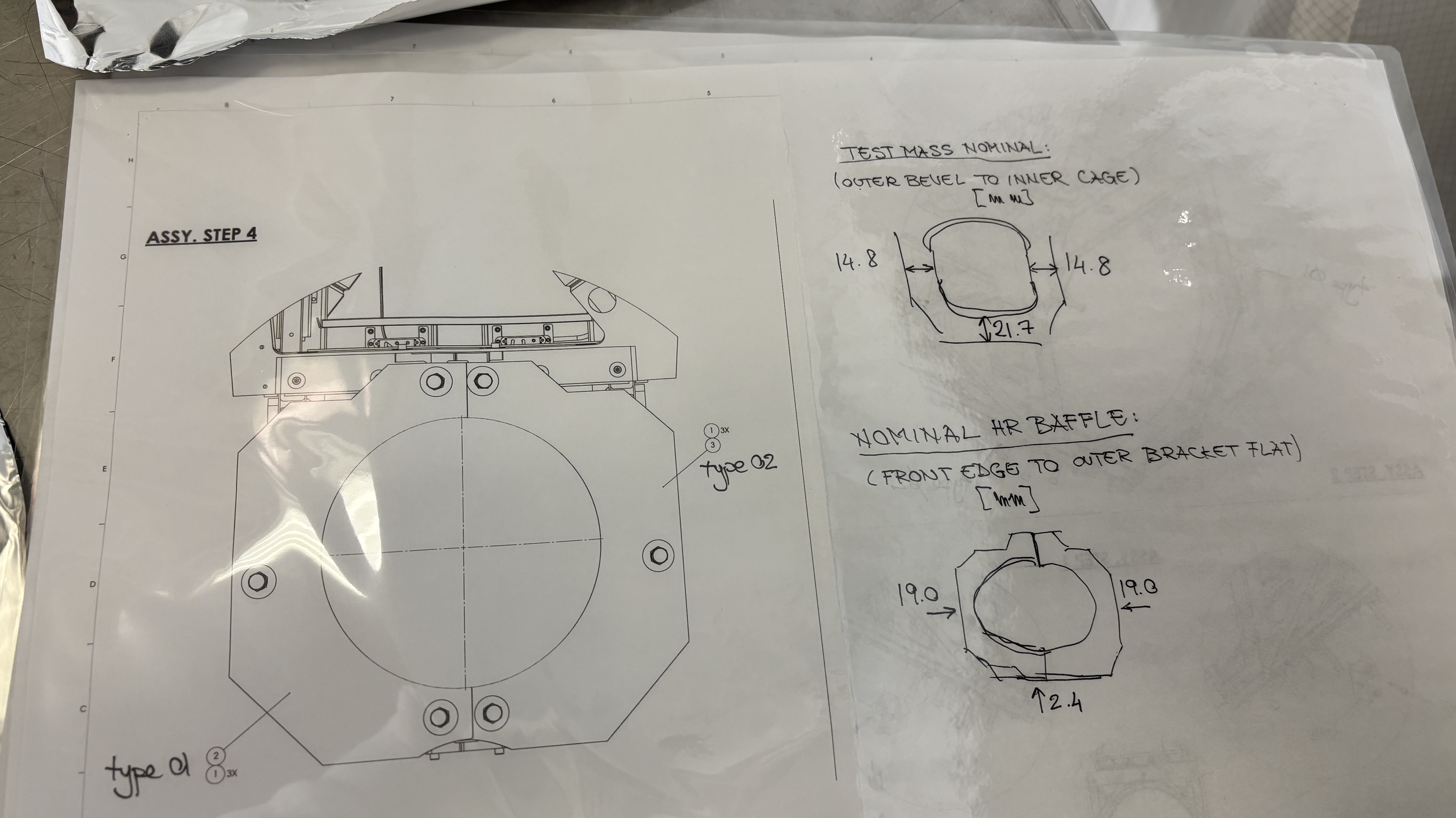
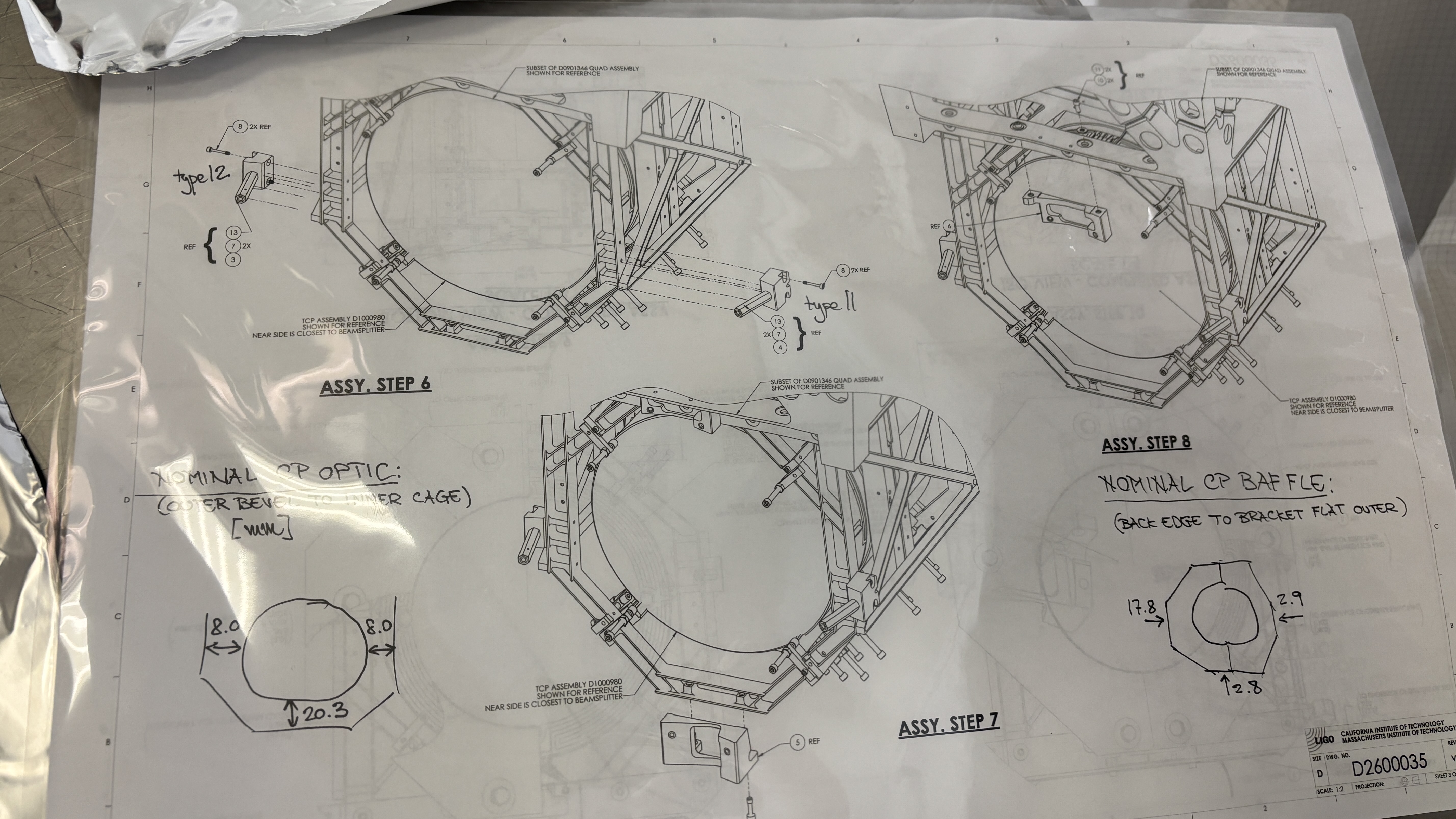
For reference I got these numbers from the following e-drawing files:
HR cage baffles: DCC D2500081 FULL ASSEMBLY D2500081 A+, SLIC, QUAD SUS CAGE BAFFLE ASSY2.easm
CP cage baffles: DCC D2600035 D2600035 A+ SLIC CP SUS CAGE BAFFLE ASSY-15deg review2.EASM
For the keen eye you'll notice that the CP optic and the tests mass are not at the same height when in reality they should be. Because the CP optic isn't quite well aligned to the cage in this drawing in an IAS sense, it's ok because the baffle IS well aligned to the optic so the relative numbers we would use to align are, well, relative and hold true.
R. Crouch, J. Oberling, B. Weaver, I. Abouelfettouh
We have completed the BBS test stand alignment. After several rounds of yaw adjustment and figuring out the mechanics and what was rubbing where, we finally arrived at a yaw alignment within tolerance with everything torqued down and no rubbing in the SUS chain. In comparison, pitch alignment was a few twists on the adjustable mass in the PUM, maybe 20 minutes in total. The final pointing alignment deviations (yaw direction assuming a top-down view):
After the pointing alignment was complete we then moved back to the AR side to check that the position had not changed. The BBS cage has not been moved on the ISI, so our alignment of the cage reported here is still valid. The results (tolerance for all is +/- 1.0 mm):
Rotating from our IAS equipment basis to the IFO axes, shifting the deviations from the AR to the HR surface, and adding the pointing alignment, the final test stand position of the BBS HR surface is shown in the below table (CW = clockwise; CCW = counterclockwise; reported assuming a top-down view):
| Target | Actual | Deviation | Tolerance | |
| X | -202.6 mm | -202.3 mm | +0.3 mm | +/-1.4 mm |
| Y | -184.1 mm | -183.8 mm | +0.3 mm | +/-1.4 mm |
| Z | -83.1 mm | -83.2 mm | -0.1 mm | +/-1.0 mm |
| Pitch | -446 µrad (up) | -431 µrad (up) | +15 µrad (down) | +/-55 µrad |
| Yaw (from -X axis) | -785.918 mrad (CW) | -785.758 mrad (CW) | +160 µrad (CCW) | +/-190 µrad |
I've kept the yaw angles in radians for consistency, but converting them to degrees gives a target yaw from the -X axis of 45.0298° CW and an actual yaw of 45.0206° CW, with a deviation of 0.0092° CCW.
We've left the IAS equipment in the West Bay near the test stand in case we need to take a look at alignment again, but as of now the test stand alignment is complete.
R. Crouch, J. Oberling, I. Abouelfettouh, O. Patane
As Ibrahim reported here, we have completed the first round of BBS position alignment (I say first round as we still have to do the pitch/yaw alignment, and that has the potential to change the position alignment so we may be doing this again). In the basis of our alignment equipment, which is set normal to the AR face of the BBS, the deviations from nominal are:
If we rotate these deviations to the XYZ axes using the BBS yaw we get deviations along those axes. I'm using the target BBS yaw for this (specifically, the AR surface yaw from the +X axis of 45.1056°), as we have yet to measure or align the actual BBS yaw, so this is more of an estimate at this point but will work for now (it takes a yaw change on the order of several degrees to change this calculation at the 0.1 mm level, so this is a pretty good estimate); this will be tightened up once we align the BBS pointing and revisit the positioning. The results (the tolerances rotate with the deviations, hence the change in X and Y):
The below table gives the target position of the center of the BBS's AR surface and the current position based on the above estimate of the XYZ deviations (all units are in mm):
| Axis | Target Position | Actual Position | Deviation | Tolerance |
| X | -160.4 | -160.5 | -0.1 | +/- 1.4 |
| Y | -226.3 | -225.8 | +0.5 | +/- 1.4 |
| Z | -83.1 | -83.2 | -0.1 | +/- 1.0 |
The next step in the alignment is to use the FARO to set up a total station/laser autocollimator combo looking along the target surface normal of the HR surface of the BBS. This will be used to align the BBS pitch and yaw. Once that is done we'll have to re-check the BBS position alignment (again, using the AR surface of the BBS) to ensure the pointing alignment did not change the optic's position (which may happen in this case as the BBS is currently, as Ibrahim reports, "quite yawed").
R. Crouch, B. Weaver, I. Abouelfettouh, J. Oberling, R. Thompson
Today we placed and aligned the BBS SUS cage on the WBSC2 ISI. In the morning we rough placed the SUS, and thought we had done a really good job on the first attempt. However, that was fed by a misread of how the Build/Inspect function in PolyWorks, well, works, and upon doing a more thorough measurement (directly measuring a constraining plane to inform SMR radius compensation instead of letting PolyWorks handle it automatically) we found there was a position and rotation error to the cage.
In the afternoon we moved the SUS cage around until things looked really good. We were well within our +/-1.0 mm XYZ tolerance, but once the SUS had been fully dog clamped to the ISI things shifted (as they do). In this case, it was roughly 0.5 mm in the +Y direction. All of our measurement points except one are within tolerance, so we called this good enough for SUS cage placement. To end, Ryan and I measured the circle that's defined by the lower section of the Figure 8 (the round section of the SUS cage that surrounds the BBS) on both the HR and AR sides of the cage. The first attachement shows the position deviations of the 4 points we used for cage placement/alignment and the current position of the HR and AR Figure 8; all except the Y axis position of 1 point are within our tolerance. The second attachment shows the rotation of the SUS cage w.r.t. the ISI; the angles listed are in degrees and are measured from the positive axes they are associated with (so X Ang is measured from the +X axis). These 2 lines show that the SUS cage is rotated roughly 400 - 500 µrad CCW (top-down view) from nominal.
Next up is to set up a total station looking at the AR face of the BBS to precisely align the optic to the ISI.


R. Crouch, J. Oberling, B. Weaver, S. Appert
We are done with the surveying of the aLIGO BS on the mechanical test stand. I'm still working on processing the data but can give a quick overview of where things stand:
I'm working on a larger alog tying together all of our BS and WBSC2 measurements (WBSC2 support tube ends, BS in-chamber, and BS on the test stand) to provide a more complete picture of the BS alignment as we have measured it these last couple of weeks (it's going to be a long one); this alog will have the full set of data from the various test stand measurements. In addition, the SUS and IAS teams met yesterday to discuss our path forward. We decided that, despite the error seen in pointing on the test stand, we will align the BBS to its nominal position and pointing w.r.t. the ISI on the test stand. Once back in-chamber we will use the BBS SUS cage position as the metric for adjusting HEPI to once again place the BBS in its nominal in-chamber position; pointing will be restored with the BS optical lever, as originally planned. I'll write up a RODA documenting this decision and upload it to the DCC ASAP.
This completes LHO WP 13210.
Edit: Some spelling and grammar clean up.
Adding some photos I took throughout the test stand measurements Tagging EPO.


Robert, Mitchell
During HAM3 chamber work yesterday the lower panel of the MCB2 panel was removed. This was needed for a clear path for the SPI. There were concerns that the removal would be difficult. The tolerence on the holes in the panels put strain and binding pressure on the screws going into the gussets. A few of the screws needed to gentle coaxing with patience and some Isopropal alcohol. Eventually they all came out without breaking or seizing. No pictures of the removal process were taken.
Pictures of the baffles added to HAM3 will be documented in a different alog.

Summary:
The problem of "Sense" pin of OMCA QPD1 short-circuited to the BHDS structure (alog 90029 from yesterday) was tracked down to the free "sense" wire inside the QPD enclosure touching the aluminum part inside the enclosure. We solved the problem by trimming the wire short.
Merely opening the QPD enclosure broke the short circuit temporarily:
We lifted the OMCA QPD1 from the BHDS while QPD2 is still attached to the BHDS and confirmed that the sense pin for the QPD1 is conductive to the QPD1 enclosure but not to the BHDS. As soon as we opened the back of the QPD1 enclosure, the short-circuit to the enclosure was broken.
It seemed that the free part of the sense wire was a bit too long and bowed in the enclosure, allowing the tip of that wire to touch the inside wall of the enclosure itself (see Elenna's first image in her comments).
Cutting the sense wire short broke the short circuit permanently:
I cut the wire short such that it cannot touch the enclosure (Elenna's second picture), reassembled the enclosure and confirmed that there's no short circuit between the sense pin and anything else.
Repeating the tests:
We put the QPD1 back on the BHDS and connected the cable to the transimpedance amplifier. On the oscilloscope, it was immediately apparent that the terrible 60Hz noise (which was 6.5V p-p) was gone (Elenna's 3rd picture).
We repeated the flashlight test, all segments responded with O(1)mV negative voltage (i.e. positive output minus negative output from the TIA amplifier was negative few mV maximum) while the dark offset was O(0.1mV).
We also measured the dark noise. It seems that all measurements for both QPD1 and QPD2 were limited by the noise of the TIA. Low frequency noise especially 60Hz and its harmonics varied from channel to channel, but in all cases it seemed that there's very little difference between the noise measured with QPD connected VS the noise without QPD. As such, I'll just show here a few examples. First attachment is the QPD1 segment 1 noise with the QPD attached, the second is the same thing but without QPD connected to the front panel of the TIA. They look identical. The third one is the QPD1 segment 4 (with QPD attached, not much different without QPD). The fourth one is the QPD2 segment 3 (with QPD attached, not much different without QPD).
There's no reason to suspect that QPD1 for OMCA is broken (nor QPD2).


Here are photos of the QPD housing with the back removed. You can see a long unsoldered wire that we identified as the "sense" wire with conducitivity tests. This is pointed out with the pink arrow. You can also see an extra mystery wire pointed out by the blue arrow. We don't know what that wire is attached to. The wire pointed by the blue arrow is actually the shielding wire which is connected to pin 1.
The after photo shows the sense wire after Keita clipped it short, pointed out with a pink arrow.
I have also included a photo of the oscilloscope image of segment 1 of both OMCA QPDs.


Zoom of Cable Table Bracket 1 (CTB-1), which collects - (1st Floor) the D25 end of the D2400343 PD concentrator cable SPI_HAM3_[031-034] (hidden from view), and - (2nd Floor) the D25 end of the D2400342 quadrupus picomotor cable SPI_HAM3_[001-004] and sends them into - (1st Floor) the ST1 end of 28 AWG D25 cable SPI_HAM3_014 - (2nd Floor) the ST1 end of 22 AWG D25 cable SPI_HAM3_012Zoom of Cable Table Bracket 2 (CTB-2), which collects - (1st floor) IFO MEAS A/B single-element PDs' duopus - (2nd floor) IFO REF A/B single-element PDs' duopus and sends them into - (1st floor) Cable D, i.e. SPI_HAM3_032 of the D2400343 PD concentrator. - (2nd floor) Cable E, i.e. SPI_HAM3_031 of the D2400343 PD concentrator.Zoom of Cable Table Bracket 3 (CTB-3), which collects - (1st floor) OL ISIK QPD B - (2nd floor) FBR PWR REF/MEAS single-element PDs' duopus and sends them to - (1st floor) Cable B, i.e. SPI_HAM3_034 of D2400343 PD concentrator - (2nd floor) Cable C, i.e. SPI_HAM3_033 of D2400343 PD concentrator