Ibrahim, Rahul
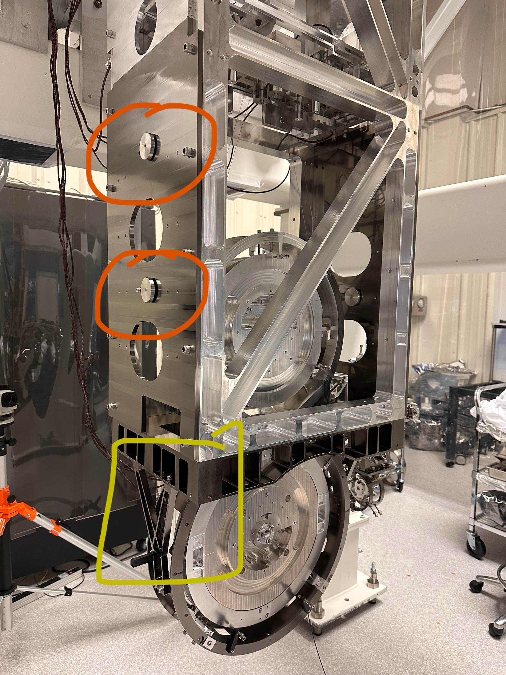
The first round of B&K test results for BBSS & HRTS were posted in LHO alog 84654 . Now were are presenting the second round of test results after making the following improvements on BBSS - (a) added four side dampers (D1101299), two on each side, (b) two lower structure Y-brace strut - D1900589. Please see figure (IMG_2926) for reference. We have also removed the four optical posts which were earlier attached to the HRTS. Finally we attached four Vibration Absorbers (D1002424) to BBSS.
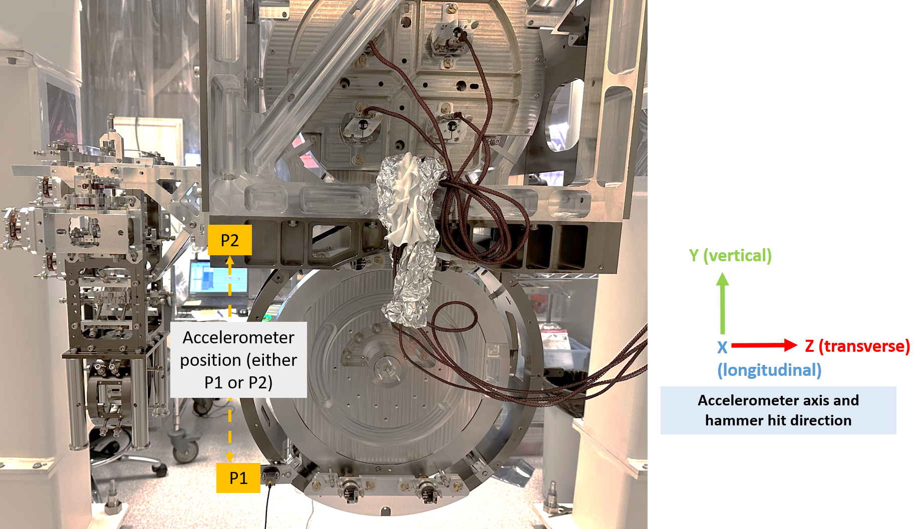
The B&K test results are attached below as a pdf document. We have taken 9 measurements with different boundary conditions, each of which is explained below. For each case the tri-axis accelerometer was mounted on the BBSS frame (marked as position P1 or P2 here) - X axis is along the longitudinal side of the BBSS, Y axis is the vertical and Z is transverse. For HRTS, it's shown in page 9 of the pdf document.
Test 1a (see page 2): case - BBSS (without HRTS) and no side dampers or Y-brace attached to BBSS, Accelerometer position P1.
Test 1b (see page 3): case - BBSS & HRTS and no side dampers or Y-brace attached to BBSS, Accelerometer position P1.
Next ,side dampers and Y-brace attached.
Test 2a (see page 5): case - BBSS & HRTS with side dampers and Y-brace attached to BBSS (No Vibration Absorbers), Accelerometer position P1. Hammer hits on the center of the structure.
Test 2b (see page 6): case - BBSS & HRTS with side dampers and Y-brace attached to BBSS (No Vibration Absorbers), Accelerometer position P2. Hammer hits on the center of the structure.
Test 3 (see page 7): case - BBSS & HRTS with side dampers and Y-brace attached to BBSS (No Vibration Absorbers), Accelerometer position P1. Hammer hits on the side of the structure (left or right).
Test 4 (see page 8): case - BBSS & HRTS with side dampers and Y-brace attached to BBSS (No Vibration Absorbers), Accelerometer position P2. Hammer hits on the side of the structure (left or right).
Test 5 (see page 9): case - BBSS & HRTS with side dampers and Y-brace attached to BBSS (No Vibration Absorbers), Accelerometer attached to HRTS. Hammer hits on HRTS.
Next ,side dampers Y-brace and Vibration Absorbers attached.
Test 6a (see page 11): case - BBSS & HRTS with side dampers, Y-brace attached to BBSS and Vibration Absorbers, Accelerometer position P1. Hammer hits on the center of the structure (X axis or longitudinal direction).
Test 6b (see page 12): case - BBSS & HRTS with side dampers, Y-brace attached to BBSS and Vibration Absorbers, Accelerometer position P1. Hammer hits on the center of the structure (Y axis or vertical direction).
Test 6c (see page 13): case - BBSS & HRTS with side dampers, Y-brace attached to BBSS and Vibration Absorbers, Accelerometer position P1. Hammer hits on the center of the structure (Z axis or transverse direction).
Test 7a (see page 14): case - BBSS & HRTS with side dampers, Y-brace attached to BBSS and Vibration Absorbers, Accelerometer position P1. Hammer hits on the side of the structure (X axis or longitudinal direction).
Test 7b (see page 15): case - BBSS & HRTS with side dampers, Y-brace attached to BBSS and Vibration Absorbers, Accelerometer position P1. Hammer hits on the side of the structure (Y axis or vertical direction).
Test 7c (see page 16): case - BBSS & HRTS with side dampers, Y-brace attached to BBSS and Vibration Absorbers, Accelerometer position P1. Hammer hits on the side of the structure (Z axis or transverse direction).
Test 8a (see page 17): case - BBSS & HRTS with side dampers, Y-brace attached to BBSS and Vibration Absorbers, Accelerometer position P2. Hammer hits on the center of the structure (X axis or longitudinal direction).
Test 8b (see page 18): case - BBSS & HRTS with side dampers, Y-brace attached to BBSS and Vibration Absorbers, Accelerometer position P2. Hammer hits on the center of the structure (Y axis or vertical direction).
Test 8c (see page 19): case - BBSS & HRTS with side dampers, Y-brace attached to BBSS and Vibration Absorbers, Accelerometer position P2. Hammer hits on the center of the structure (Z axis or transverse direction).
Test 9a (see page 20): case - BBSS & HRTS with side dampers, Y-brace attached to BBSS and Vibration Absorbers, Accelerometer position P2. Hammer hits on the side of the structure (X axis or longitudinal direction).
Test 9b (see page 21): case - BBSS & HRTS with side dampers, Y-brace attached to BBSS and Vibration Absorbers, Accelerometer position P2. Hammer hits on the side of the structure (Y axis or vertical direction).
Test 9c (see page 22): case - BBSS & HRTS with side dampers, Y-brace attached to BBSS and Vibration Absorbers, Accelerometer position P2. Hammer hits on the side of the structure (Z axis or transverse direction).
The raw data (.csv files) generated by the B&K software are stored at the following location,
/ligo/home/rahul.kumar/Desktop/scripts/bnk_csv_files

Attached below is a pdf document in which I have repeated tests 6abc and 7abc accelerometer / hit location data, but with the HRTS removed (called as test 8abc and 9abc). In both the cases the Vibration Absorbers (VA) are attached to the BBSS. There are no VA on the HRTS.