jeffrey.kissel@LIGO.ORG - posted 19:18, Wednesday 20 November 2013 - last comment - 19:13, Thursday 05 December 2013(8656)
ITMX Arm Cavity Baffle B&K Hammer'ed
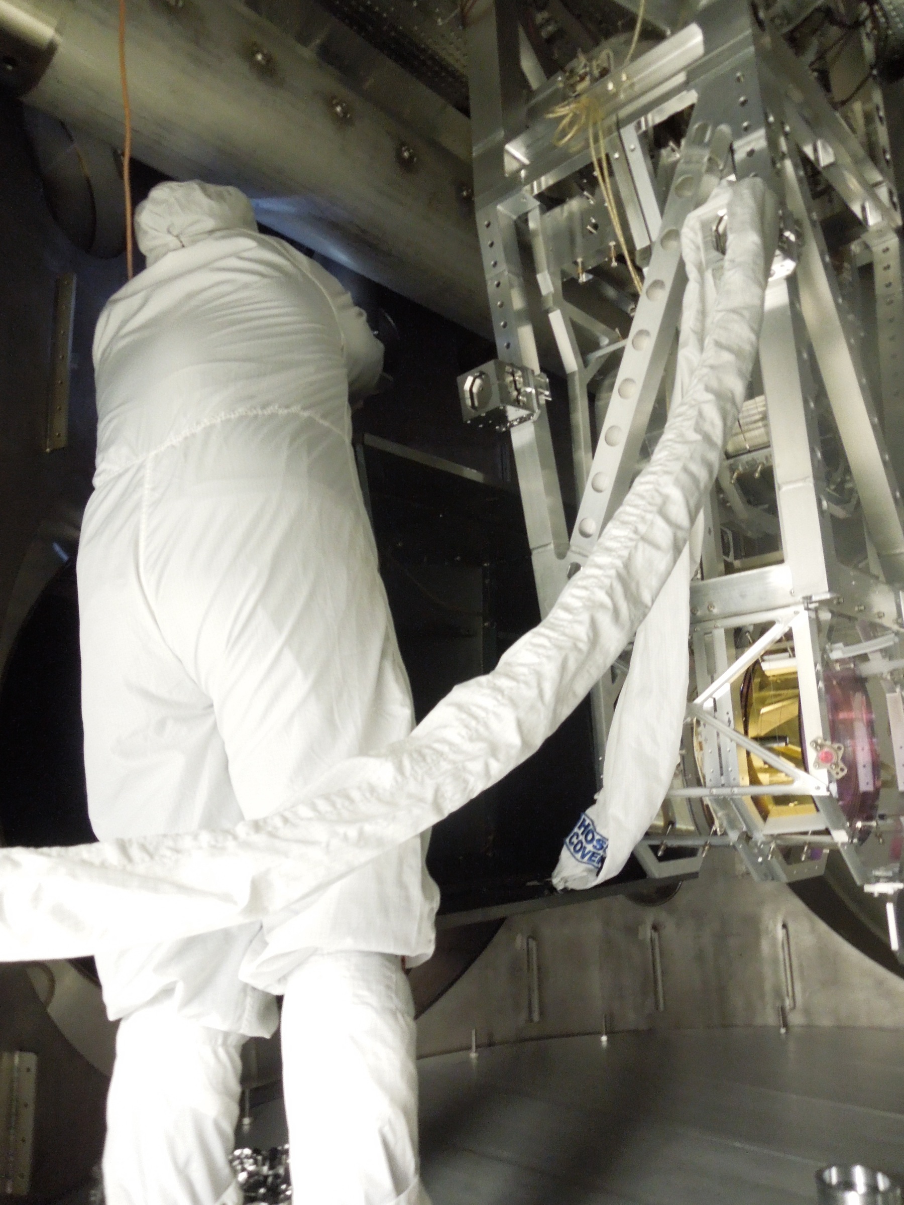
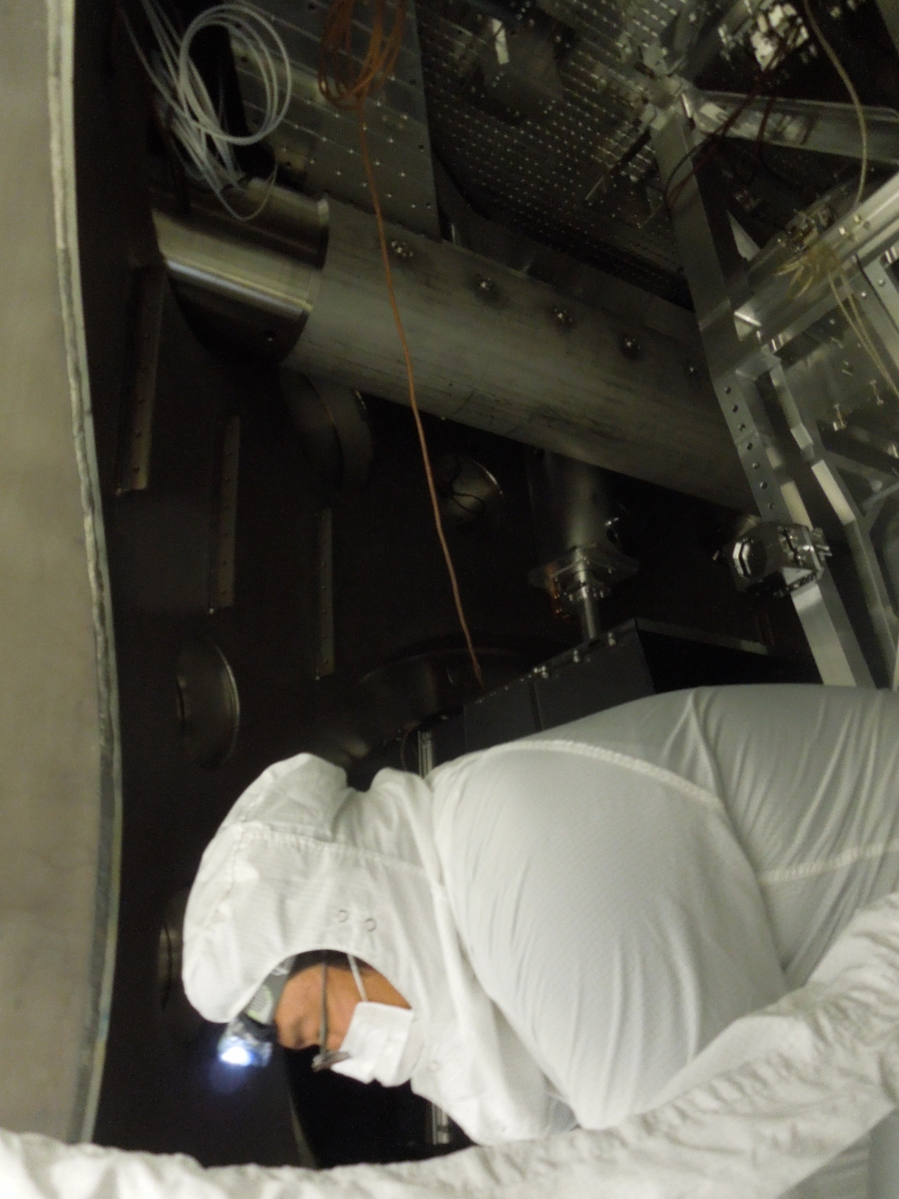
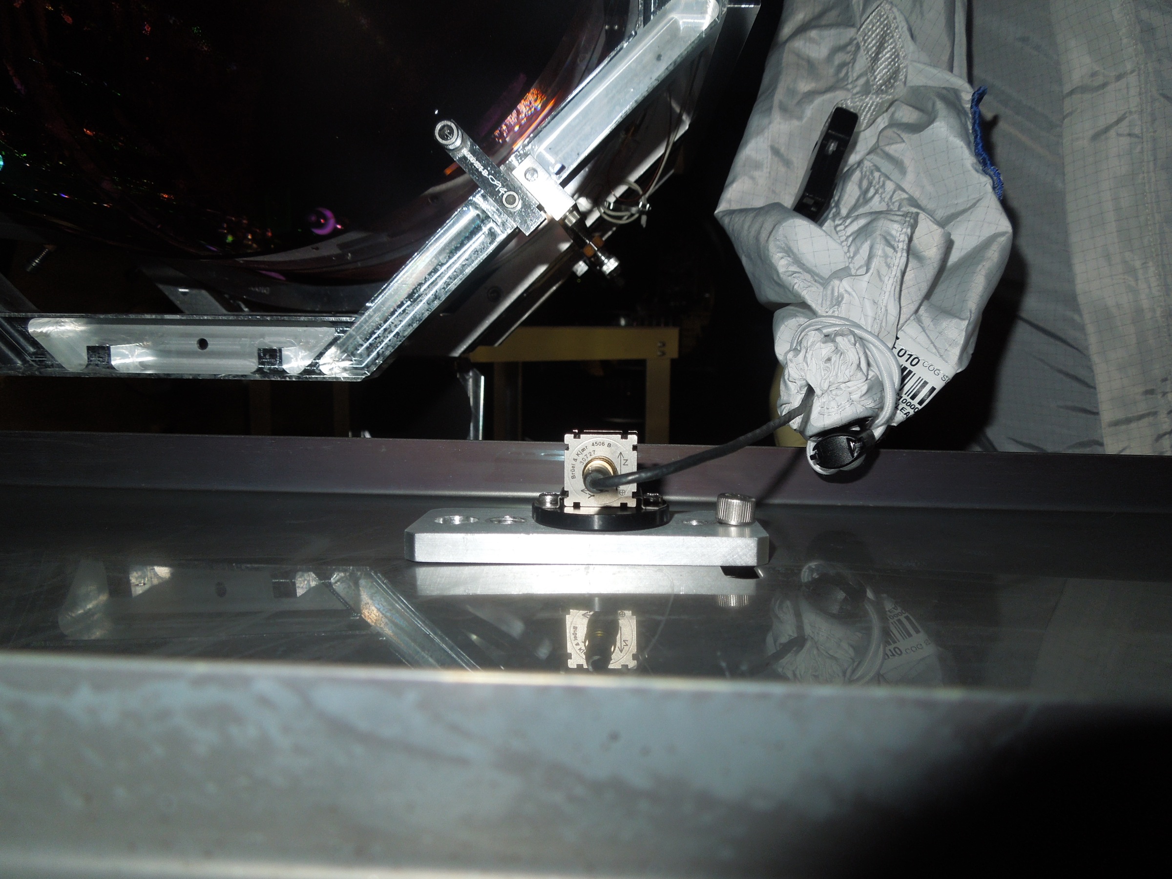
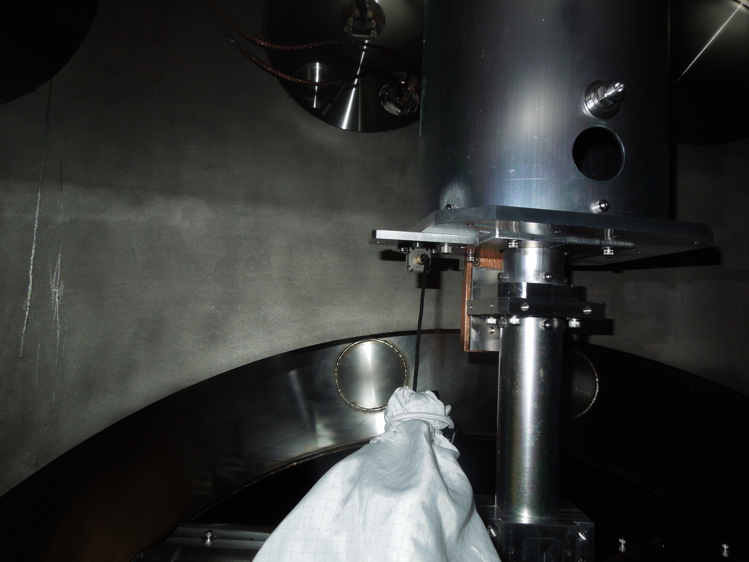
J. Kissel, T. Vo

Because of the recent resonant features seen in ISI-ITMX that seemed to have been fixed by a simple lock and unlock of the ITMX Arm Cavity Baffle (see LHO aLOG 8632), I asked "has anyone ever taken B&K hammer transfer functions of the ACB?" The answer was a resoundingly loud "no" (I am Jack's complete lack of surprise). Me and my big mouth volunteered to do it, and there was a tiny window of opportunity before Thomas cleaned up the chamber, so Thomas and I pioneered the first B&K measurements of the ITM ACB. Details of the measurement setup and execution below.

Again, I don't know how to properly export the data (as indicated in LHO aLOG 8654), so you'll have to be patient regarding the results. Note that obtaining official plots of the results should not in any way be considered as a hold-up for chamber close out.

Of course, after taking the measurements and cleaning up the chamber -- because we *touched* the baffle -- we had Sebastien run a quick set of ISI-ITMX transfer functions, and it informed us we're not-at-all done battling this bumbling oaf of a baffle (see LHO aLOG 8653). This should be considered a hold-up for chamber close out. Round three, first thing tomorrow!

-----------
Details:
We took two distinct measurements:
(1) With the accelerometer on the suspended baffle itself, using a unused slotted bolt hole in the inside middle, closest to the ITM HR surface. This test was just a shot in the dark, to see if we could get a nice driven transfer function of the suspended stage, since there have been no prior attempts with this generation of the ACB baffle. At first glance from the B&K software plots, it looks like a complete mess, so it will most likely either be a completely confusing / useless or completely depressing result.

DSCN0206.jpg (or pg 3 of the .pdf) shows a picture of the accelerometer from inside the baffle looking out back toward ITMX. As is (hopefully) resolvable in the picture, ACC +X = ITMX -L, ACC +Y = ITMX -T, ACC +Z = ITMX +V. The Y impact was on the (ITMX) +T face, bottom corner, closest to the ITM, in the (ITMX) -T direction. The X impact was along the bottom edge of the (ITMX) -L face, in the +L direction.

(2) With the accelerometer on the bottom of the support structure's tube (shown in DSCN0209.jpg). One can't see it in the picture, but the accelerometers axes were aligned with the global IFO's axes, such that ACC +X = Points down X arm towards ETMX, ACC +Y = Points down the Y Arm towards ETMY, and ACC +Z = Points up with local gravity (the same as ITMX's +V). The X & Y impacts were made towards the bottom of the outer, support structure, "eddy current damping 8 dia," tube (D1002564, of the assembly D1200275). Man, that thing rung like a bell when Thomas whacked it...

The files live on the B&K laptop only, in
C:Users\ligo\Desktop\SUS Hammer Test\ITMX\BandK\
and are called
(1x) SimpleHammerDisplay3-ArmCavityBaffleBaffle-ISIfloating-SuspendedElements_Ximpact.pls
(1y) SimpleHammerDisplay3-ArmCavityBaffleBaffle-ISIfloating-SuspendedElements_Yimpact.pls
(2x) SimpleHammerDisplay3-ArmCavityBaffleBaffle-ISIfloating-StructuralElements_Ximpact.pls
(2y) SimpleHammerDisplay3-ArmCavityBaffleBaffle-ISIfloating-StructuralElements_Yimpact.pls
Images attached to this report
Non-image files attached to this report

Comments related to this report
Results are attached below.
First page is comparing X-X and Y-Y of the "structural element"
* Main resonnances are around 80Hz, 120Hz, 180Hz
Second page is comparing X-X and Y-Y of the "suspended element"
*Data is very noisy
Non-image files attached to this comment