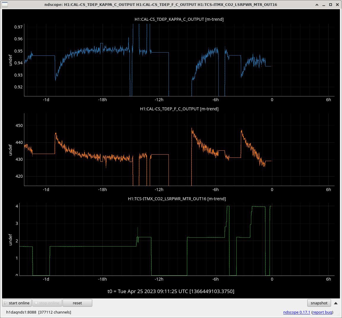
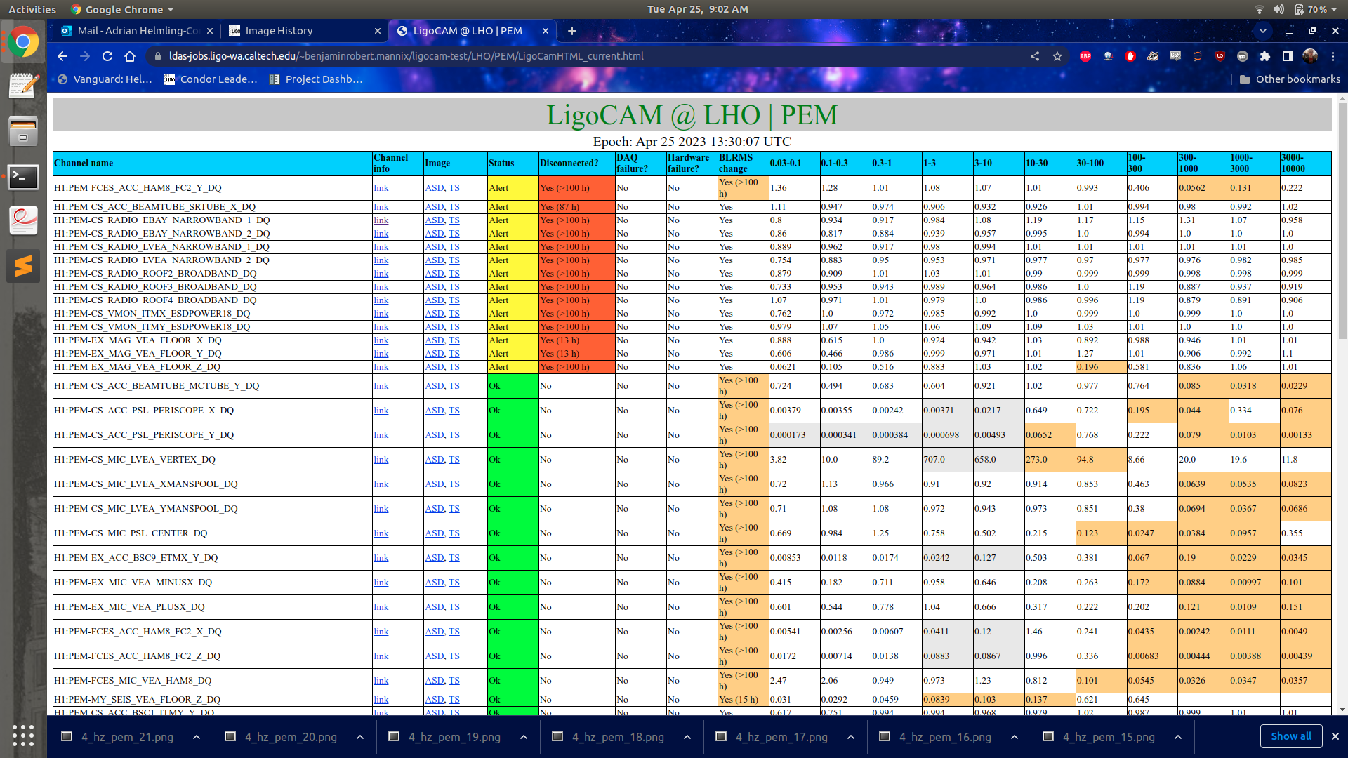
LIGOCAM shows H1:PEM-EX_MAG_VEA_FLLOR_X/Y/Z_DQ as disconnected. I confirmed that (i) the magnetometer was still in place (ii) the power supply was on and (iii) the magnetometer box was running. I couldn't follow the triaxial signal cables from the box to the PEM racks - the cables are bound up with a whole bundle under the beamtube near the BRS. I still don't know why they're marked as failing.
JoeB, JeffK, TonyS, DriptaB, RickS
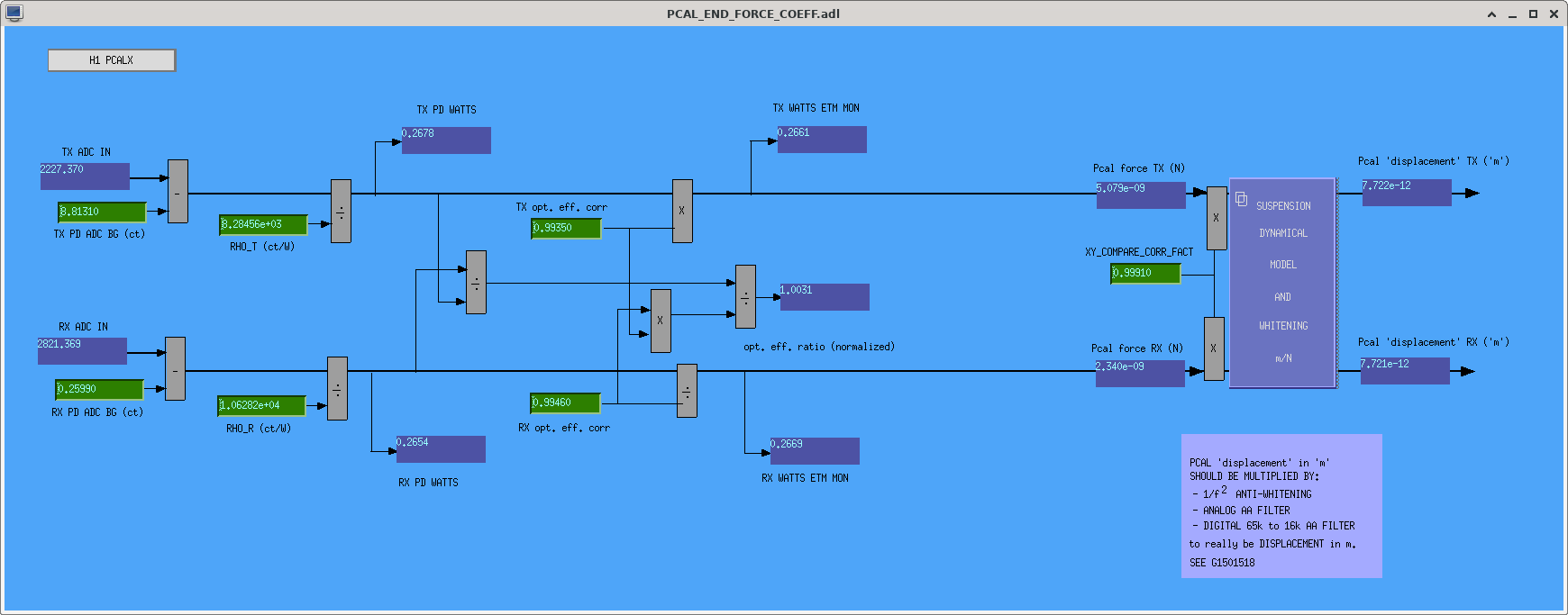
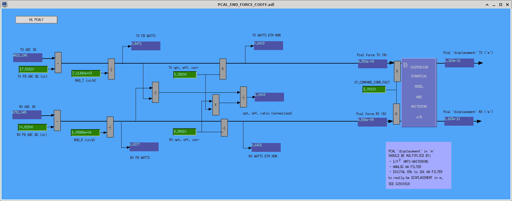
Using Dripta's python script (/ligo/svncommon/CalSVN/aligocalibration/trunk/Projects/PhotonCalibrator/scripts/O4/Pcal_calibration_EPICS.py) to calculate the required EPICS values and write the text file with the caput commands (/ligo/svncommon/CalSVN/aligocalibration/trunk/Projects/PhotonCalibrator/O4_EPICS_calibration/Pcal_LHO_CAPUTfile_O4run_2023-04-25.txt), we updated the EPICS values required by JoeB's new front-end code to calibrate the Pcal power sensor outputs. A copy of the script that generated the .txt, Pcal_calibration_EPICS_2023-04-25.py, is written in the O4_EPICS_calibration directory with the .txt file. Note that it must be run from the scripts directory.
Images of the new PCAL_END_FORCE_COEF.adl MEDM screens are attached below.
The caput commands that were executed are:
caput H1:CAL-PCALX_FORCE_COEFF_RHO_T 8284.5616
caput H1:CAL-PCALX_FORCE_COEFF_RHO_R 10628.1901
caput H1:CAL-PCALX_FORCE_COEFF_TX_PD_ADC_BG 8.8131
caput H1:CAL-PCALX_FORCE_COEFF_RX_PD_ADC_BG 0.2599
caput H1:CAL-PCALX_FORCE_COEFF_TX_OPT_EFF_CORR 0.9935
caput H1:CAL-PCALX_FORCE_COEFF_RX_OPT_EFF_CORR 0.9946
caput H1:CAL-PCALX_XY_COMPARE_CORR_FACT 0.9991
caput H1:CAL-PCALY_FORCE_COEFF_RHO_T 7114.8962
caput H1:CAL-PCALY_FORCE_COEFF_RHO_R 10588.6196
caput H1:CAL-PCALY_FORCE_COEFF_TX_PD_ADC_BG 17.5161
caput H1:CAL-PCALY_FORCE_COEFF_RX_PD_ADC_BG -0.8150
caput H1:CAL-PCALY_FORCE_COEFF_TX_OPT_EFF_CORR 0.9920
caput H1:CAL-PCALY_FORCE_COEFF_RX_OPT_EFF_CORR 0.9931
caput H1:CAL-PCALY_XY_COMPARE_CORR_FACT 1.0011
The EPICs records,
caput H1:CAL-PCALX_XY_COMPARE_CORR_FACT
caput H1:CAL-PCALY_XY_COMPARE_CORR_FACT
are new to the h1calex and h1caley models as of Tuesday Apr 25 2023 LHO:68959.
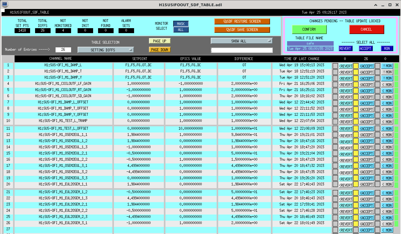
As with any new channels added to a front end, one must initialize them within the SDF system in order to accept them to make sure they stick (see instructions on how to do so in, e.g. LHO:67600).
I've initialized these variables and accepted their values as listed above just now (Apr 27 2023 ~19:00 UTC).
Mid Day Tuesday Maintenance Progress update!
There was some Wind Fence work today and that will likely be on going.
| (7:45am-8am) In-lock Charge Measurements if IFO is locked.- | -Completed |
| 8am - FAC - More Vinyl Work- | -Inprogress |
| APS door security vendor at FCES/VEA door and high bay LVEA door | -In Progress |
| 8am - EY Charge (Rahul)- | -Complete |
| 8am - Corner, then EX, then EY - Jim /CDS - Restart BSC ISI and SEIPROC models. Continuing ECR updates from HAM work last week, seiproc is getting some dolphin channels for related to eq mode. Will require daq restarts, and time to copy filters in. | -In progress |
| CDS - DAQ restart to take in 2 new Guardian nodes and remove one node - | -Complete |
| Update to CAL-CS and PCAL Models (Kissel) - | -Complete |
|
CDS - Marc - Replace two identified overheating power supplies in the CER. Mezanine Rack C1 U29-U31 LeftHandSide (LHS) +18V 5A -- (SUS C6 ITMs BS) -- Mezzanine Rack C5 U13-15 RightHandSide (RHS) -18V 5A - |
-Complete |
| EY - CDS - Move the timing from EY to Mid Y on to a single fiber strand like it is in EX. PEM EY taken offline. | -In progress |
| EY - VAC - perform functionality test on turbo/hepta pumps. - | - In Progress |
We are expecting to Start locking soon.
Daniel, Naoki and I pluggeg in the SR785 at the PSL racks to run measurements of CARM during lock and determine if we can increase the CARM gain (see alog 68967). This means we have unplugged the cable that allows us to run frequency noise injections, We will try to get carm measurements as we thermalize, and then plug in the frequency injection cable so we can return to those measurements later in the lock.
SR785 unplugged, and frequency noise injection cable plugged back in.
Plugged back in the SR785 for CARM measurements at 0600 UTC.
This morning we lost lock at 16:00 UTC (alog 68974) while the last 13Hz ETMX In-lock charge measurement was still running. So ETMX measurement isn't valid.
1. The SUS_CHARGE log doesn't properly refect that but I've edited/reloaded the SUS_CHARGE code so that in future it will continually monitor ISC_LOCK rather than just check we are locked at the start of the injection states. If we loose lock, it takes all nodes to DOWN, which will stop and clear all injections.
2. The measurement took too long, total of 18 minutes where we want <15 minutes. I'll look into the ramp times.
I reduced all 60 second ramp time to 20 seconds. This should save us 240 seconds (4 minutes).
RyanC, Rahul
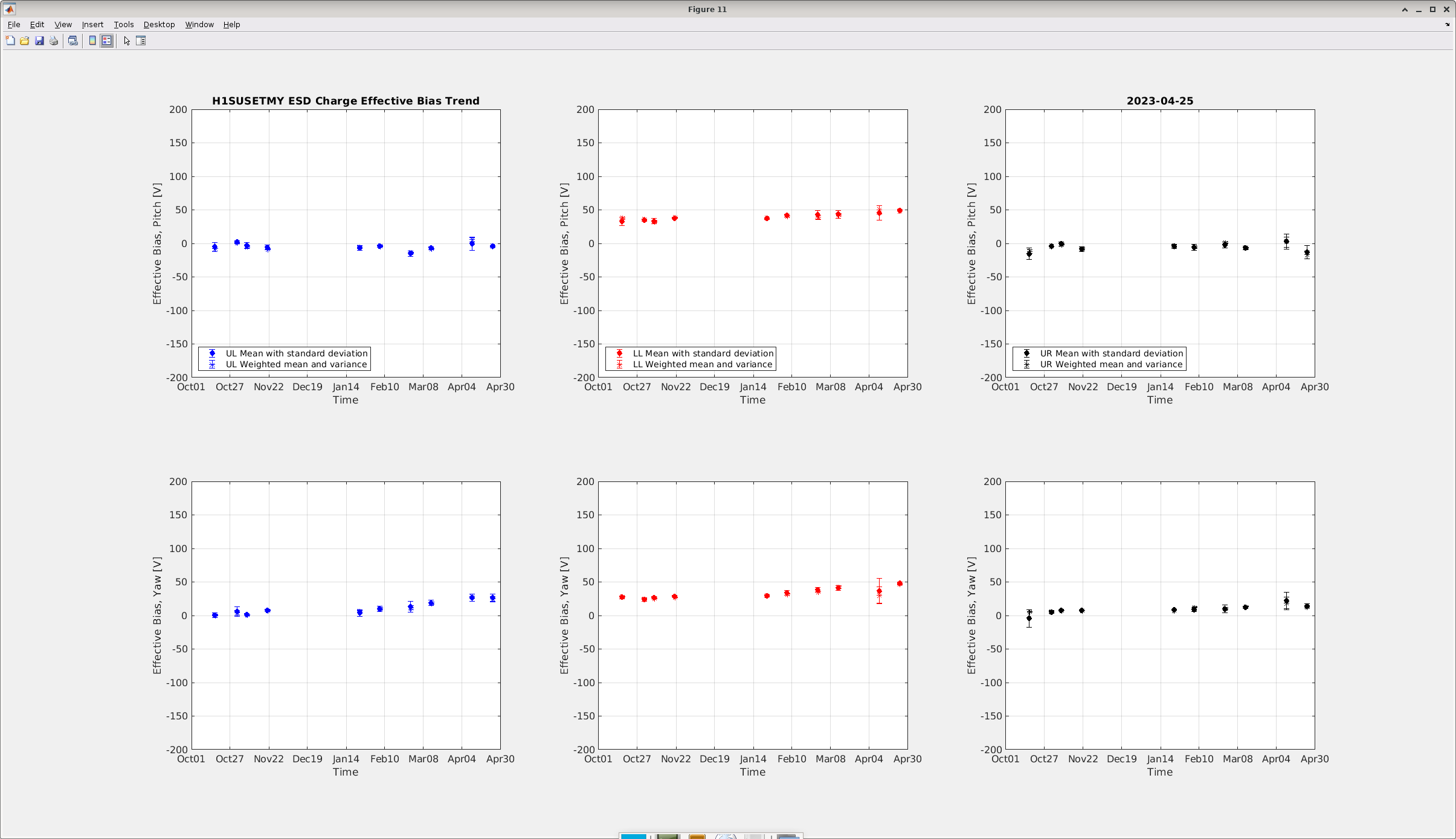
We ran the OPLEV charge measurement script for ETMY today during the maintenance and the latest plot is attached below. Due to insufficient time we took only 4 data before truncating the measurement. The effective bias voltage has not changed much from the last measurement. However Yaw (2nd quadrant) has slightly gone up from 30V to 50V and Pitch (3rd quadrant) has also increased from +2V to -16V.
Later in the evening today Austin will run the FAMIS task and post comparison plot between OPLEV and inlock charge measurement results.
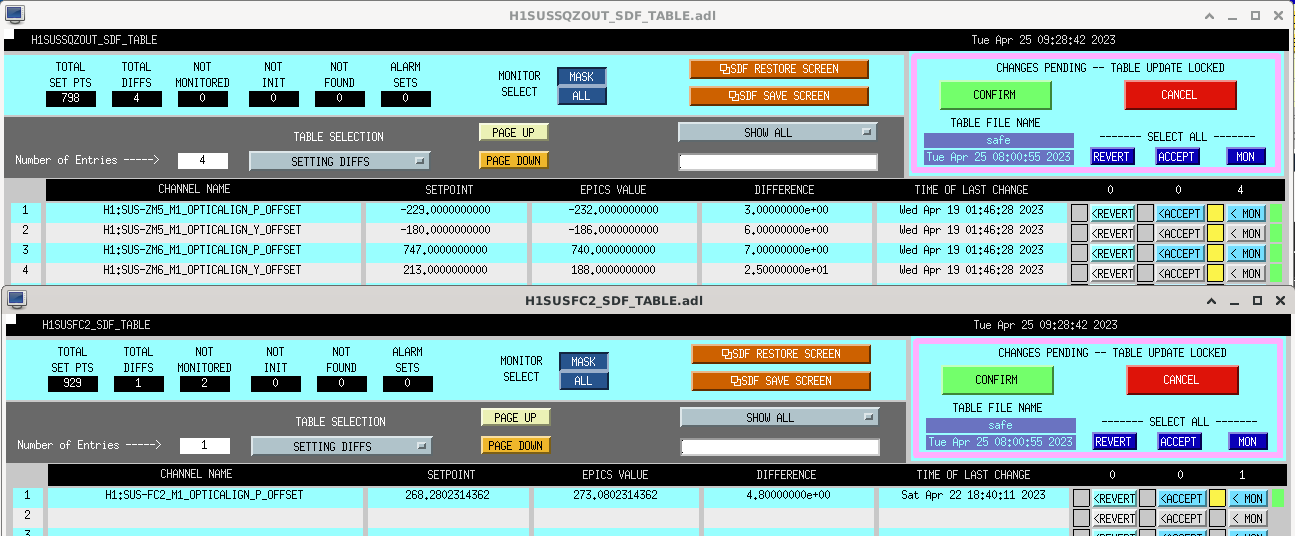
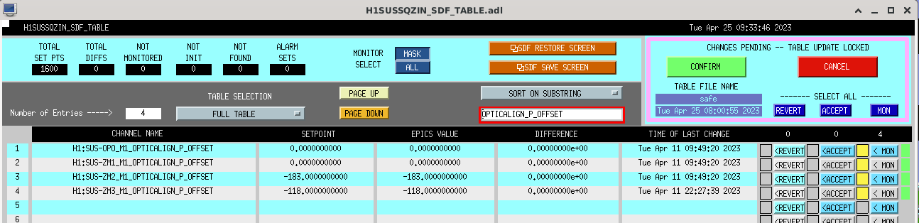
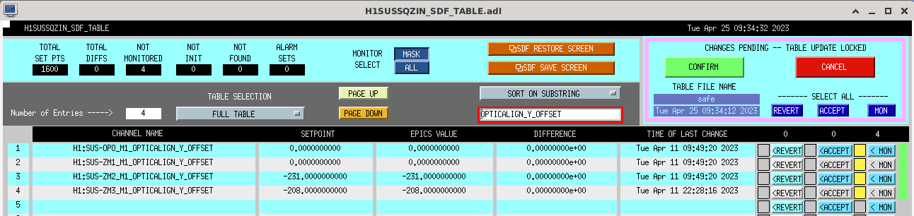
I cleaned up the SDF for the remaining suspension models that need to be added to SDF Revert. Most notable changes:
Suspension models added (name, dcuid, userapps area):
FAMIS 23748
Corner Station:
EX:
EY:
J. Kissel, D. Brown
Dan found my simple bug in the new CAL_AWG_LINES guardian; a simple mistake in ordering of the keyword arguments to he SineMultiple() function copied from the AWG_LINES guardian. Now that we're driving, for example, 24.4 Hz at 1e-10 counts (instead of 1e-10 Hz at 24.4 counts #facepalm), things work exactly and easily as expected. See attached ASD of the excitation signals driven by CAL_AWG_LINES, with the state in "LINES_ON."
Next up -- integration into ISC_LOCK guardian as a managed node.
Obviously I've loaded the bug-free code into the node, but I've also committed the changes to the userapps svn,
/opt/rtcds/userapps/release/cal/h1/guardian/CAL_AWG_LINES.py
now at rev 25396.
TITLE: 04/25 Day Shift: 15:00-23:00 UTC (08:00-16:00 PST), all times posted in UTC
STATE of H1: Commissioning
CURRENT ENVIRONMENT:
SEI_ENV state: CALM
Wind: 3mph Gusts, 2mph 5min avg
Primary useism: 0.01 μm/s
Secondary useism: 0.13 μm/s
QUICK SUMMARY:
When I Arrived the IFO Was still at Nominnal Low noise, but DARM FOM was disconnected from source.
Lock Loss immideiately after I took SEI_ENV to Maintenance.
The Lock was 3 hours 5 minutes long. Hopefully the In lock charge measurments went through.
All wall displays were updated and restarted in the control room.
All displays are switch to fomstarter aka fomcatcher
Nuc27 has a prolem with firefox. I'm working on it.
Nuc27 is rebooted and working.
Elenna, Dan
We wanted to test the original asymmetric CO2 powers we had back at 60W to see if we could get back to lower frequency noise.
Elenna had been doing some steps and measurements and I took over when she left. Elenna had set the nominal requested CO2 in lscparams to 2.7W (which is actually 4W of actual annular CO2) and I was going to come in a few hours later and take some measurements. However the TCS guardians didn't seem to take us there, probably not reloaded. I changed CO2X by hand up to 4W with the aim of coming back a few hours later to do the measurement.
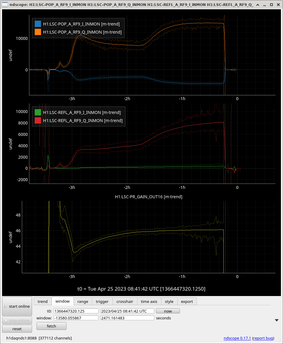
About 1.5 hours later there was a lockloss, PRG became very noisy. Looking at POP_A_RF9_{I,Q}_INMON they both doubled in counts. I didn't measure PRCL gain but maybe this CO2 change in combination with the new fixed thermalisation gain scaler increased it too much.
I didn't get a chance to do the measurements we wanted (contast, spring, frequency coupling) so I've set the nominal CO2X to 2.7W requested and reloaded the guardians. I've set the THERMALISATION guardian to IDLE to see if this will hold a longer lock. I'll come back in a few hours and see how it's doing and try to take the measurements if it survives.
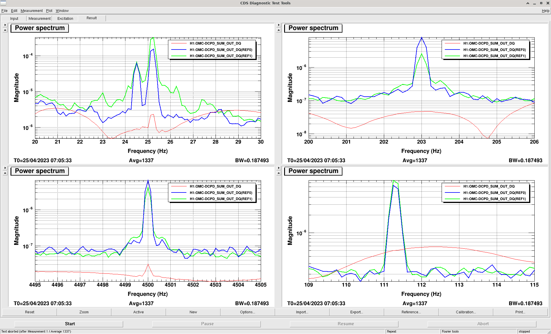
Looking at the lines before lockloss, it seems going back to an asymmetric CO2 setting 4W and 1.7W on X and Y reduces the 200 and 4500 Hz frequency noise coupling a little but increases the 25.2Hz coupling. Arm power is also slightly down by a few kW. This also looks like it will eventually reduce both the optical gain and cavity pole judging by their trends.
I think we have some promising results from this test, although it is mostly inconclusive because we were unable to get well-thermalized data. As an aside, I think many of our locklosses were related to the fact that the PRCL UGF servo trend had been measured at a different thermal state, so it might not have been properly tuned for the new CO2 settings.
CO2X at 4W, CO2Y at 1.7W
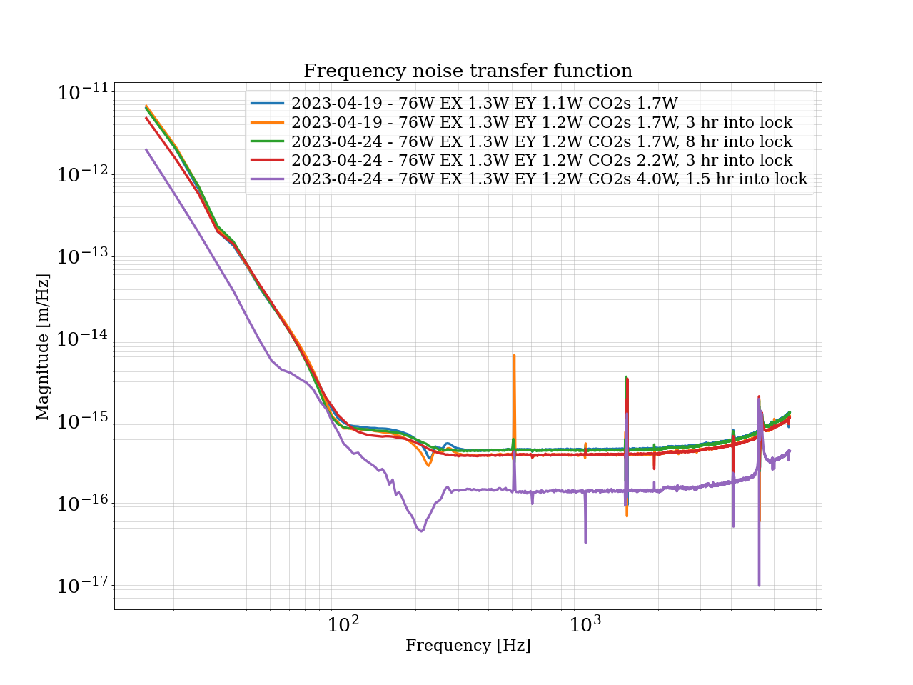
Frequency noise: according to this plot it has improved. Keep in mind we are comparing traces later in lock with a trace 1.5 hrs into the lock. However, that is a significant change.
Contrast defect: slightly worse, 2.2 mW again. Same caveat as above
DARM spring: appears improved too, again with caveats. This was measured with the SRCL offset at -165 (nominal)
The frequency noise and DARM spring plots also show the results with CO2X at 2.2W (CO2Y at 1.7W). The results show either no change or minimal change.
I think these results are promising enough that we should keep these CO2 settings in the guardian. Tonight's lock after maintenance we will remeasure these parameters while we thermalize and after thermalization (~3-5 hrs into lock). We will also monitor and adjust the PRCL gain by hand. When we do DARM spring measurements, we will take multiple measurements with different SRCL offsets.
Overnight locklosses reported in alog 68988. One unknown, one from a PI, last 3h lock ended by Tuesday maintainance.
Analysis from the modulation depth test.
Power-recycling gains for sidebands and carrier
9 MHz PRG = 54.6
45 MHz PRG = 27.2
Carrier PRG = 46.2
Reflection ratios for sidebands and carrier
9 MHz reflection ratio = 0.226
45 MHz reflection ratio = 0.316
Carrier reflection ratio = 0.063
| Channels | 9 MHz | 45 MHz | Carrier |
|---|---|---|---|
| H1:IMC-PWR_IN_OUT16 | 0.013 | 0.015 | 0.973 |
| H1:IMC-IM4_TRANS_NSUM_OUT16 | 0.013 | 0.015 | 0.972 |
| H1:LSC-REFL_A_LF_OUT16 | 0.043 | 0.068 | 0.889 |
| H1:LSC-REFL_B_LF_OUT16 | 0.041 | 0.066 | 0.893 |
| H1:LSC-POP_A_LF_OUT16 | 0.015 | 0.009 | 0.976 |
| H1:ASC-POP_A_NSUM_OUT16 | 0.015 | 0.009 | 0.976 |
| H1:ASC-POP_B_NSUM_OUT16 | 0.015 | 0.009 | 0.976 |
| H1:ASC-AS_C_NSUM_OUT16 | 0.190 | 0.509 | 0.301 |
| H1:ASC-OMC_A_NSUM_OUT16 | 0.190 | 0.557 | 0.253 |
| H1:ASC-OMC_B_NSUM_OUT16 | 0.197 | 0.635 | 0.168 |
| H1:ASC-X_TR_A_NSUM_OUT16 | 0.004 | 0.007 | 0.989 |
| H1:ASC-X_TR_B_NSUM_OUT16 | 0.004 | 0.007 | 0.989 |
| H1:ASC-Y_TR_A_NSUM_OUT16 | 0.004 | 0.007 | 0.989 |
| H1:ASC-Y_TR_B_NSUM_OUT16 | 0.004 | 0.007 | 0.989 |
Relative to https://alog.ligo-wa.caltech.edu/aLOG/index.php?callRep=68696
We seem to be reflecting more 9 and less 45. The 45 PRG has increased to 27. We appear to still have a large percentage of 9 at the AS port
TITLE: 04/25 Eve Shift: 23:00-07:00 UTC (16:00-00:00 PST), all times posted in UTC
STATE of H1: Commissioning
SHIFT SUMMARY:
- Beginning of shift was mostly waiting for ringdown from the huge EQ from earlier in the day and getting the IMC to lock after a power supply swap, log here
LOCK #1:
- Had to intervene with locking ALS and DRMI (through ACQUIRE_PRMI), but not by much
- Acquired NLN @ 00:35 UTC, where multiple measurements were done
- LOCKLOSS @ 4:38 UTC due to CARM sensor switching from B to A
LOCK #2:
- Again, had to intervene with locking ALS, though I probably should have given GRD more time to see if it could do it on its own
- Had issues with DRMI again, gave GRD ~5 minutes before intervening, I moved PRM ~35 microradians in Y and ~6 microradians in P to be able to catch PRMI
- Acquired NLN @ 5:50 UTC
- Leaving the IFO locked at NLN, Dan is currently running AWG lines and CO2 stepping from 2.2 W to 4 W
LOG:
| Start Time | System | Name | Location | Lazer_Haz | Task | Time End |
|---|---|---|---|---|---|---|
| 00:05 | ISC | Adrian | CER | N | Quick checks | 00:07 |
| 00:37 | ISC | Jeff | CR | N | Turning on PCAL/DARM lines | 03:27 |
| 01:40 | ISC | Elenna | CR | N | AWG line injections/ADS lines/DARM OLG | 05:44 |
| 06:52 | ISC | Dan | Remote | N | CO2 stepping/AWG lines | ONGOING |
Next three locklosses:
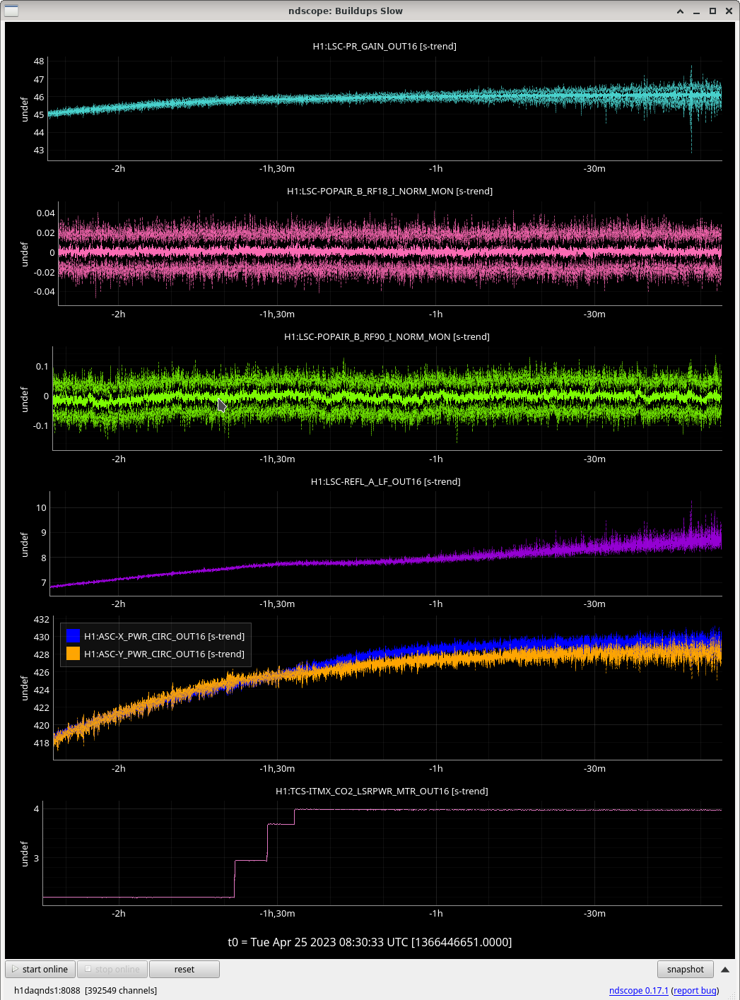
2023-04-25 08:28:29 UTC 2h30 at NLN. CO2X was increased from 2.2W to 4.0W 1h30 before lockloss. Unsure of cause. Not PI. Not Violins. Buildups attached.
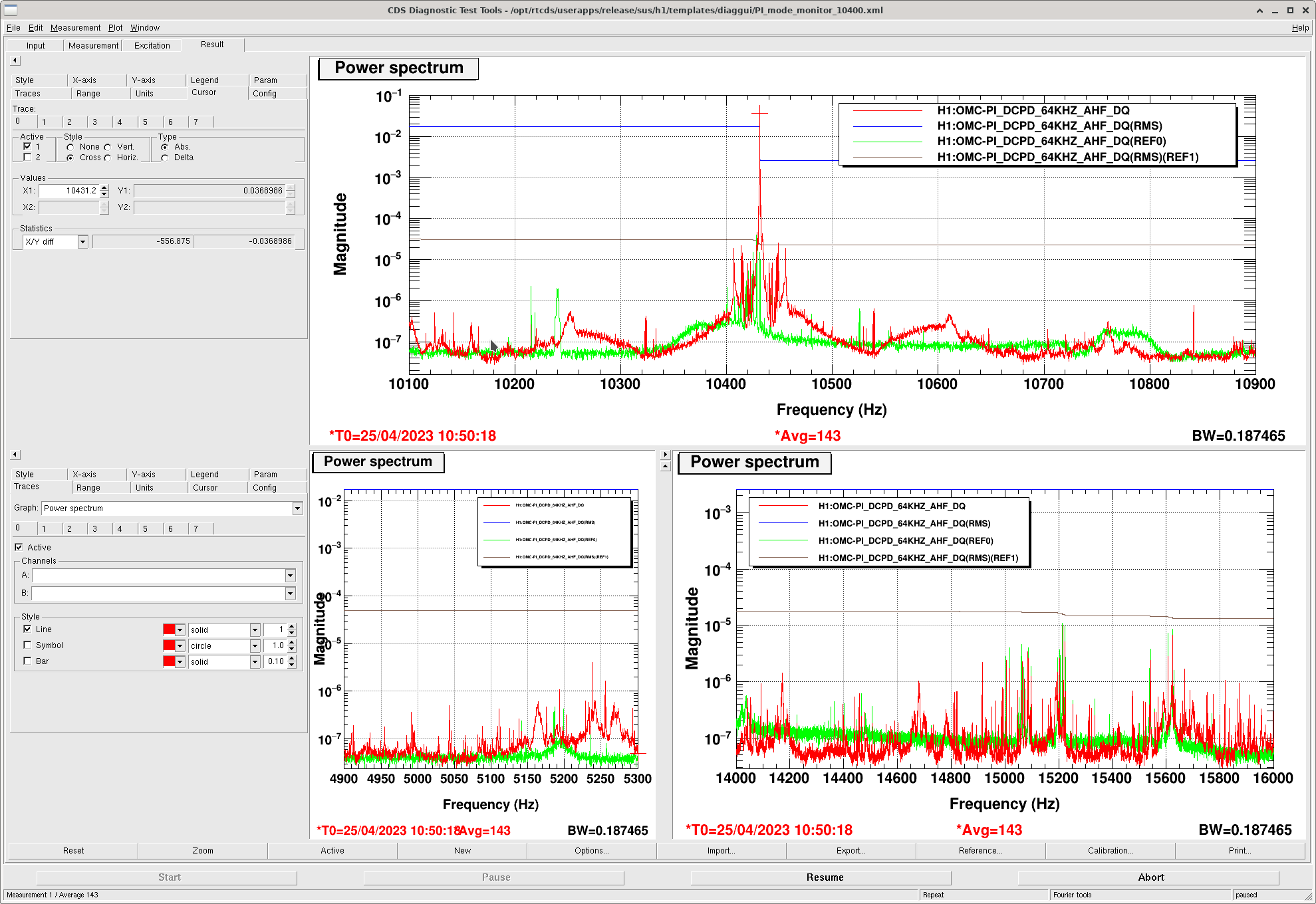
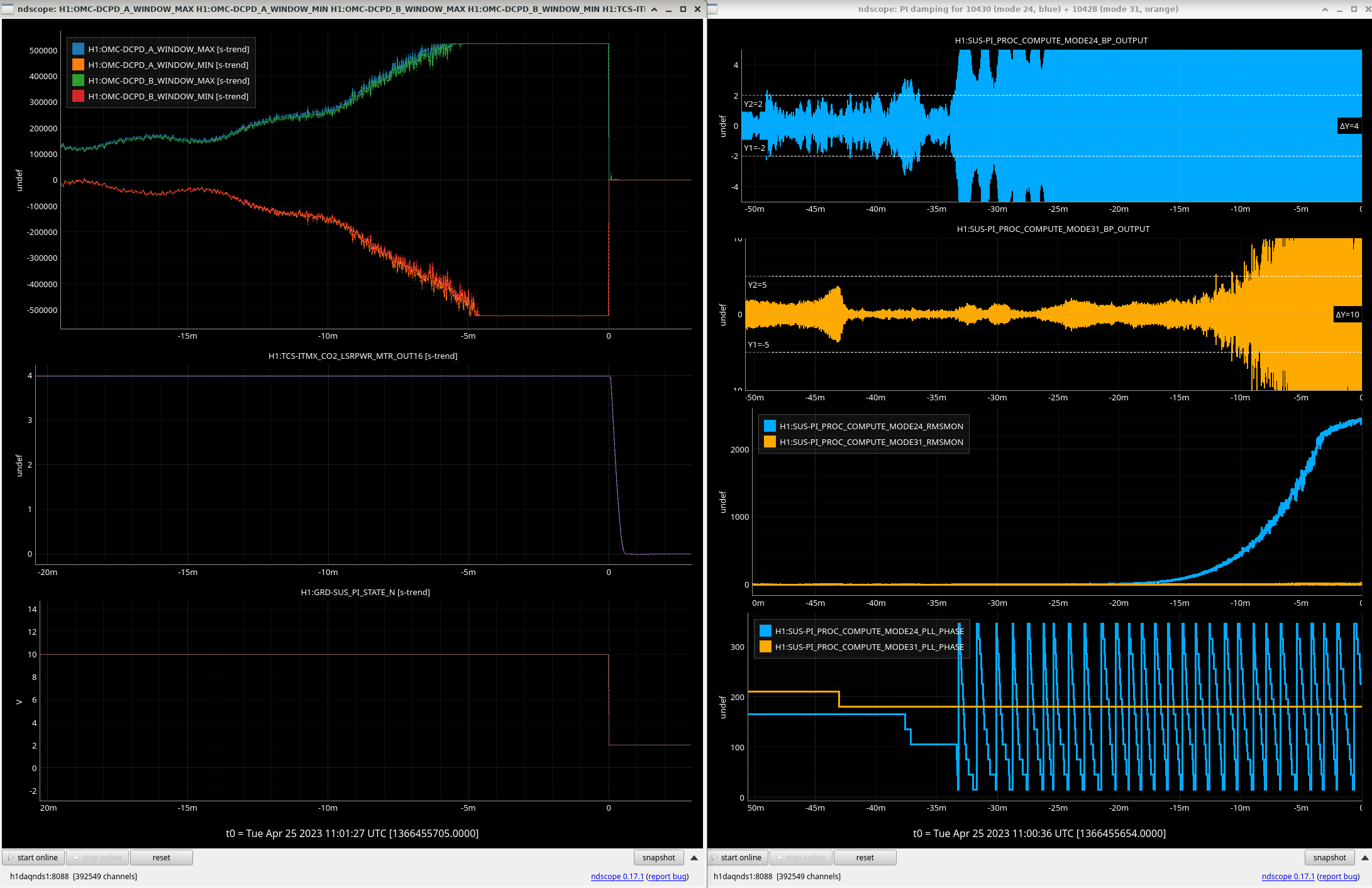
2023-04-25 11:01:27 UTC 1h30 at NLN. CO2X at 4W throughout lock. 10.4kHz PI. See attached. SUS_PI guardian was in state PI_DAMPING but didn't work well enough, maybe the mode rang up to quickly. We can make guardian smarter if these locklosses continue as it currently changes phase if the RMSMON is above a certain value rather than checking if RMSMON is decreasing. See attached.
2023-04-25 15:00:29 UTC 3h into NLN. CO2X at 4W throughout lock. Lockloss from Tuesday Maintenance start.
All locks: CO2Y at 1.7W, Ring Heaters: IX 0.4W, EX: 1.3W, IY 0W, EY 1.2W.
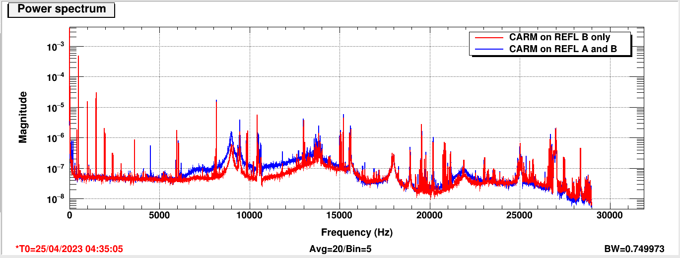
The high frequency "tail" of DARM from 5-7 kHZ, which is a region limited by frequency noise, seems to improve when the CARM sensor is switched to REFL B only. I discovered this first by accident: when we run the frequency noise injection for the noise budget, we switch CARM over to REFL B and measure the frequency noise using REFL A as an out of loop sensor.
The process by which I switch the sensor is one that Craig described to me, and I have done several times:
To switch back to two sensors, I reverse the steps above.
I have attached the high frequency spectrum of DARM from the 64kHz channel, showing the reduction in noise in DARM when CARM is just sensed on REFL B. I believe this is occurring because this is the region where CARM is gain limited. What I don't understand is how switching to one sensor (and correcting for the gain), is causing such a large change.
I was hoping to switch over to REFL A only and see if this holds true for the other PD, but I forgot I was running ADS on at the time and I railed the ADS causing a lockloss.
I see that this is likely a math error on my part. When I made the change I thought "12 dB on each sensor, 24 dB on one sensor", but I need to add the gains, meaning factor 4 gain on two sensors, factor 8 gain on one, or 18 dB (oops!). I have been inadvertently increasing the CARM gain by a factor of two when moving to one sensor. I'm impressed that I was able to do this without causing any problems. If we feel we have room to increase the CARM gain, we can improve the high frequency tail on DARM. I'm not sure what kind of gain margin we have, but apparently 6 dB extra does not cause immediate problems. Happy accidents and/or math errors?
I think alog67214 and alog67584 are the latest measurements of CARM OLG in Feb. The gain margin was ~13dB at that time. It might be better to measure it again with current 76W configuration.
Looking at the CARM OLGs Naoki posted, we were running with a lower UGF than in O3. In O3, we pushed the CARM UGF up to around 25 kHz to suppress the HF noise we saw. You can't go beyond 37 kHz because of the FSR.
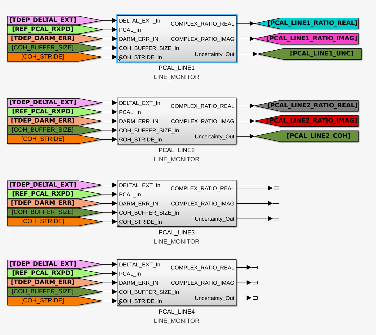
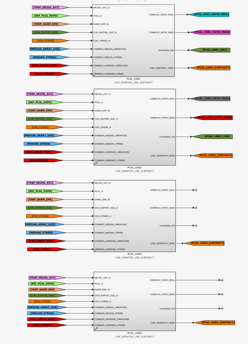
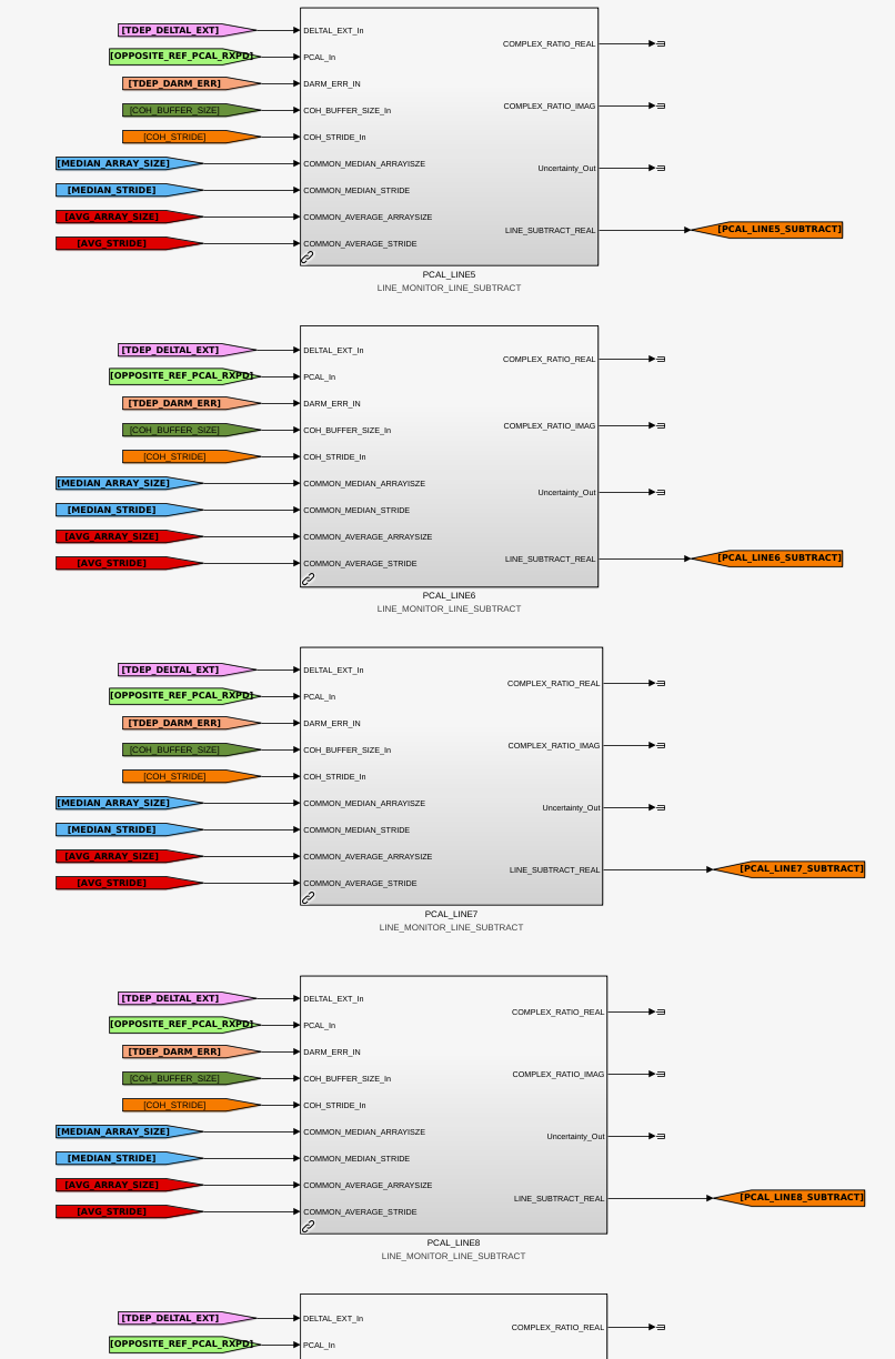
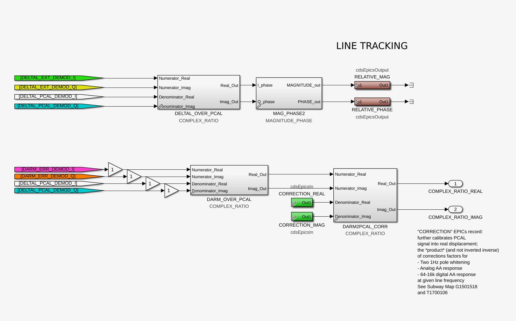
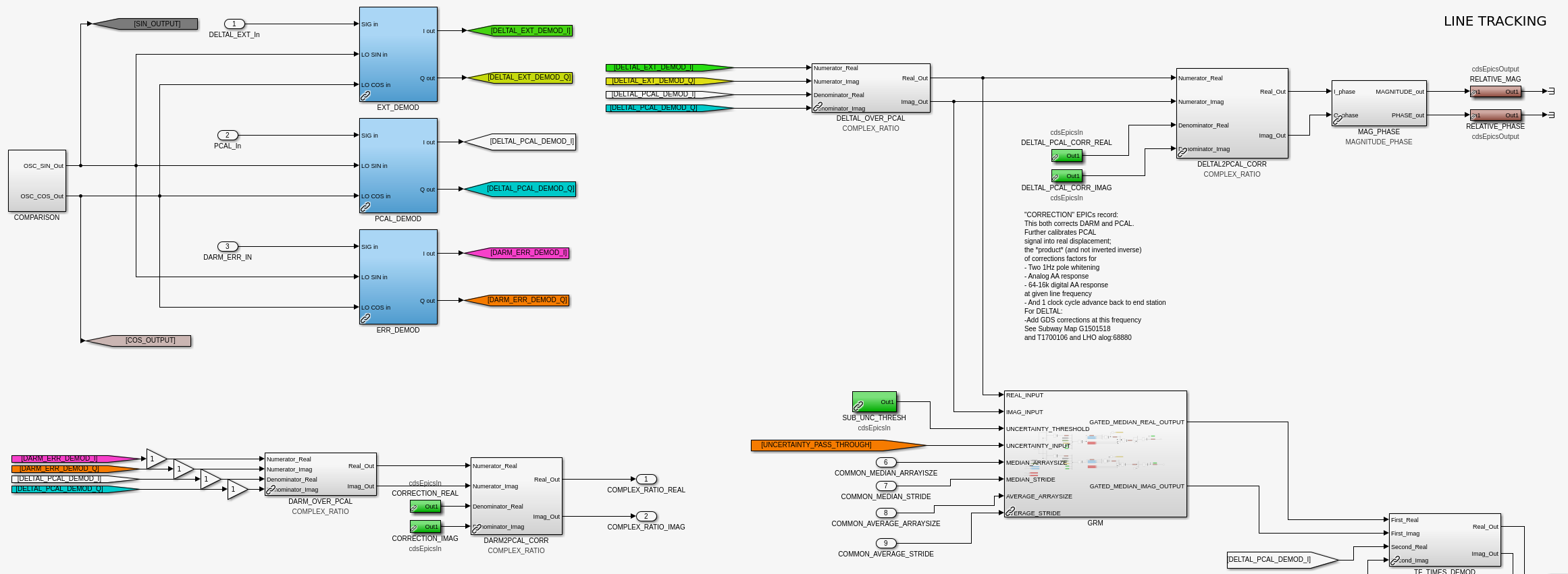
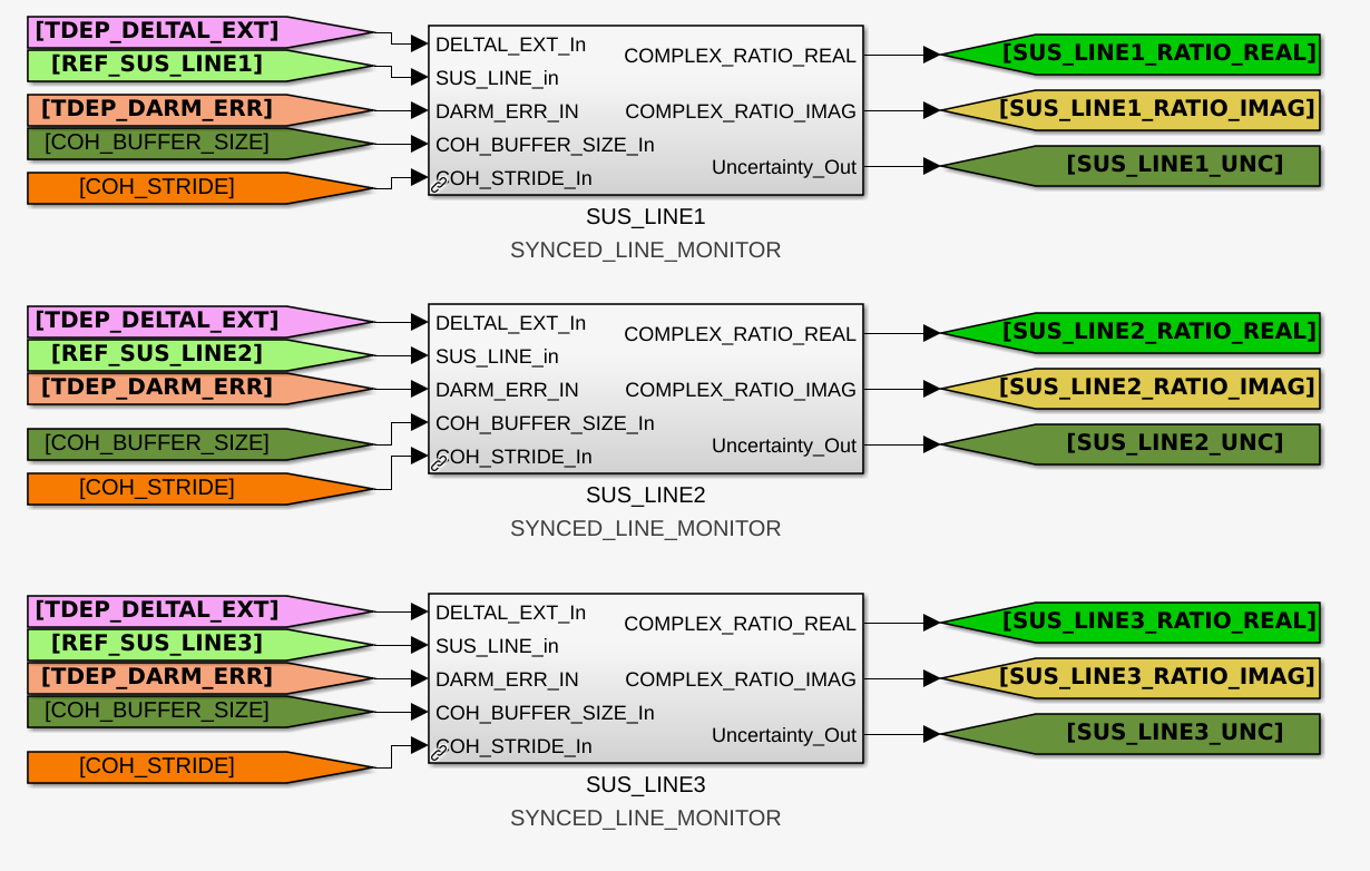
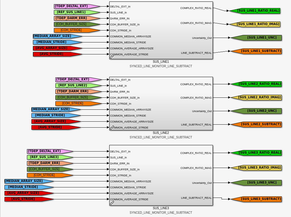
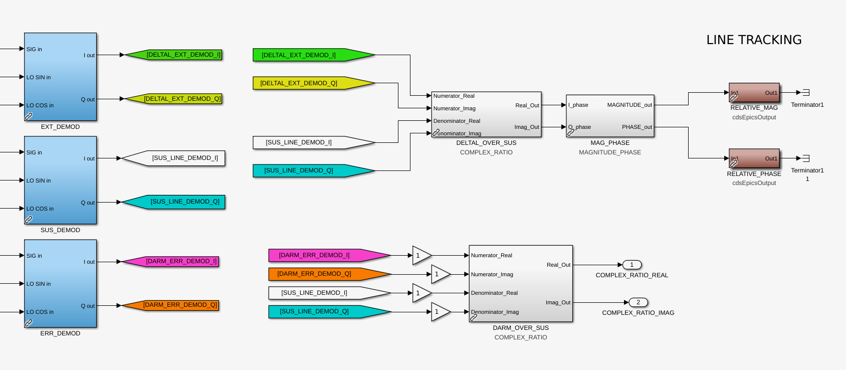
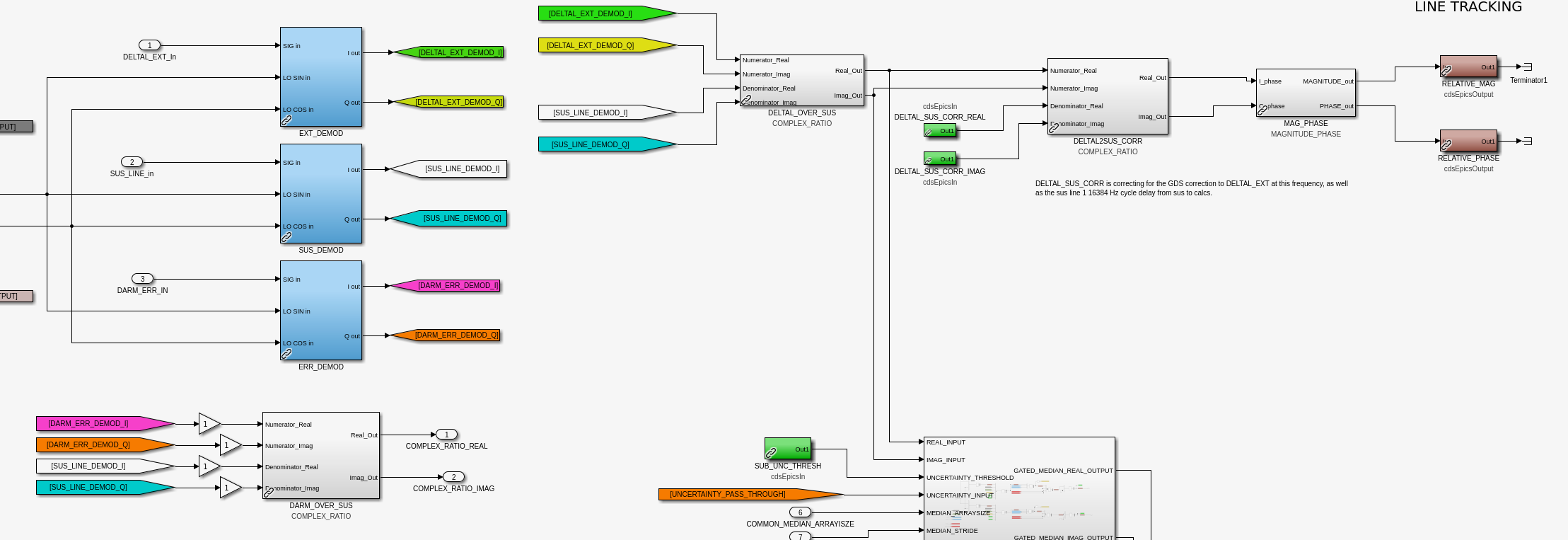
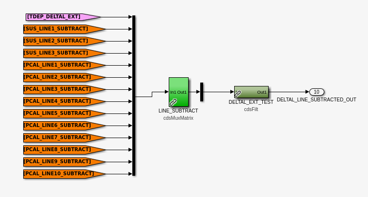
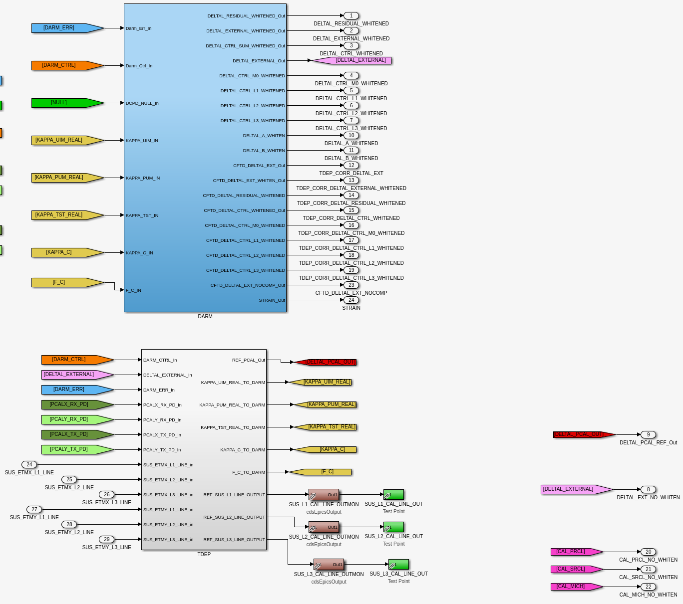
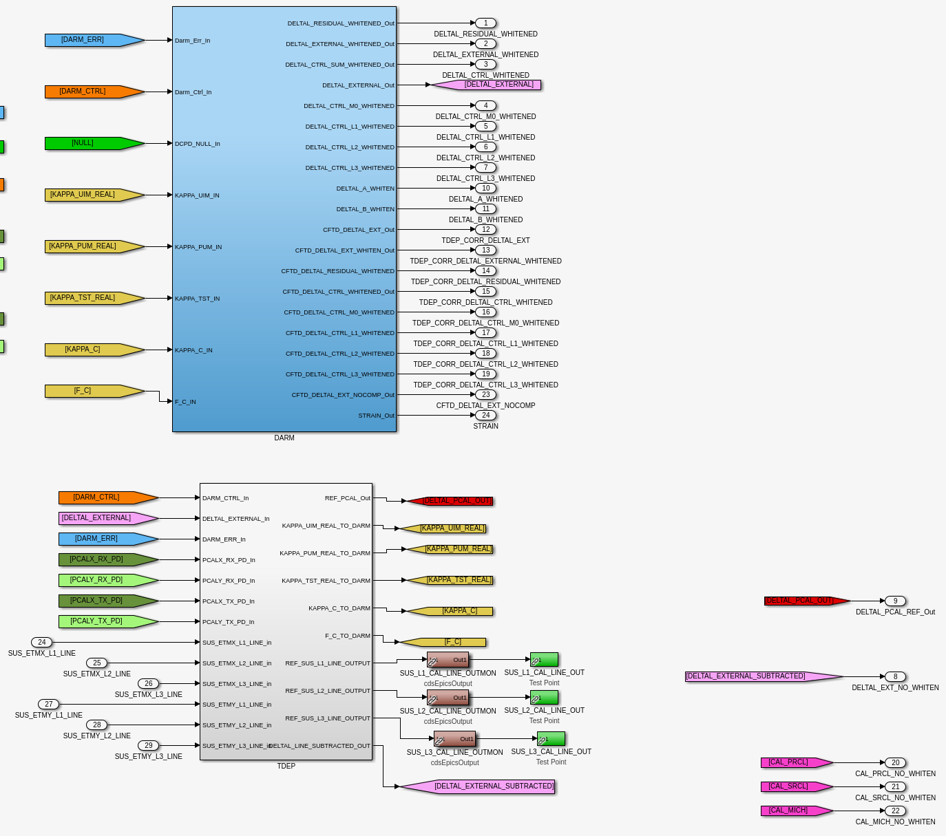
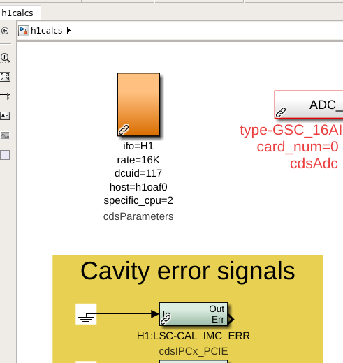
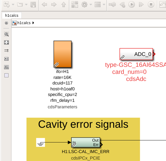
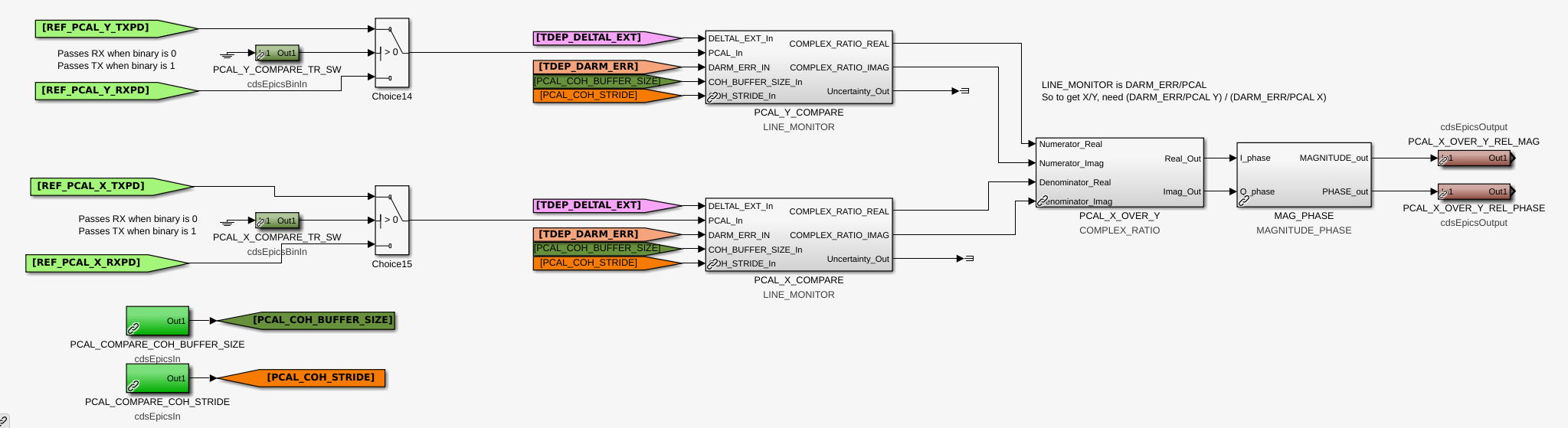
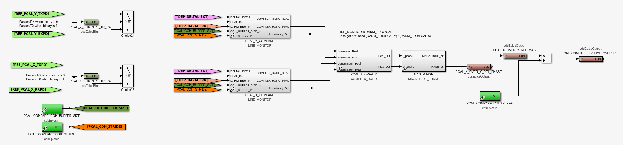
J. Kissel, J. Betzwieser WP 11138 Importing more needed infrastructure from LLO (LLO:64213) I've updated some library parts which take in the following changes to the corner-station CAL-CS model (h1calcs): - Adding more infrastructure to be able to demodulate the new(ish) PCALX systematic error lines, - Adding a few more EPICs records that represent corrections to PCAL, DARM, and DELTAL channels, after finding a new level of understanding about correction factors, delays, and advances from LHO:68880 - Along the way, this brings in a (what will be unused here at LHO) alternative method to subtract all the calibration lines from DELTAL_EXTERNAL - Adding an EPICs record that represents how the ratio between PCALX and PCALY should be corrected for known / expected differences - And with all the extra demodulation infrastructure, it means we need to re-introduce the setting that adds one 16 kHz clock cycle delay before sending channels out over RFM (the rfm_delay=1) into the cdsParams parameter block to allow for the extra time to compute what should be sent from the corner station to the end station (which is also unused her at LHO). Attached are a ton of "before" vs. "after" screenshots. I'll walk through the meaning of these changes in detail in the comments in the fullness of time. For now, the message that I've imported the changes to /opt/rtcds/userapps/release/cal/common/models/ CAL_CS_MASTER.mdl CAL_LINE_MONITOR_MASTER.mdl and committed the rfm_delay=1 parameter add to the /opt/rtcds/userapps/release/cal/h1/models/ h1calcs.mdl to the svn repo, and tested that the h1calcs model successfully builds.
Here's the list of channels added to CALCS as a result of this change. No channels have been removed. jeffrey.kissel@cdsws03:~$ check_model_daq_configuration h1calcs --------------------- file times ---------------------- Tue Apr 25 07:53:26 2023 = Model build time Tue Apr 18 10:21:21 2023 = Current configuration load time DAQ configuration is changed, processing... ++: slow channel H1:CAL-CS_TDEP_PCAL_COMPARE_XY_LIVE_OVER_REF added to the DAQ [... see h1calcs_channelchange_list.txt ...] ++: slow channel H1:CAL-CS_LINE_INJ_SWSTAT added to the DAQ Total number of DAQ changes = 1220 (1220 additions, 0 deletions)
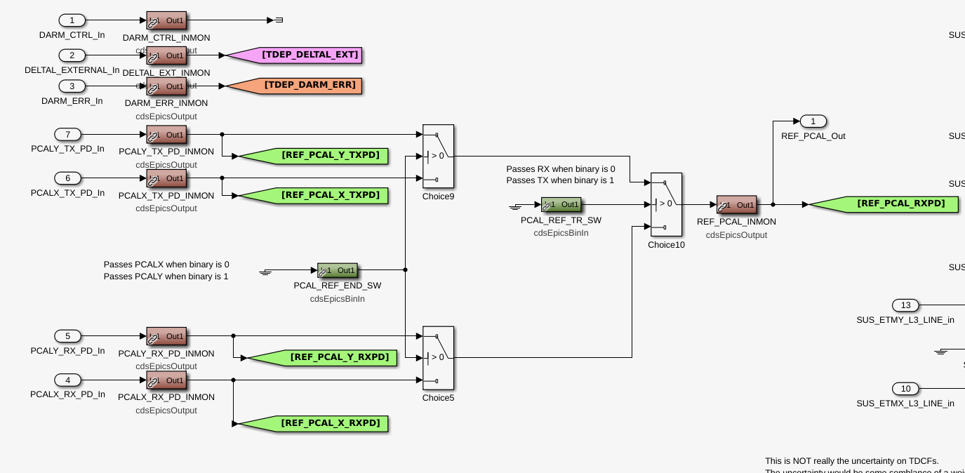
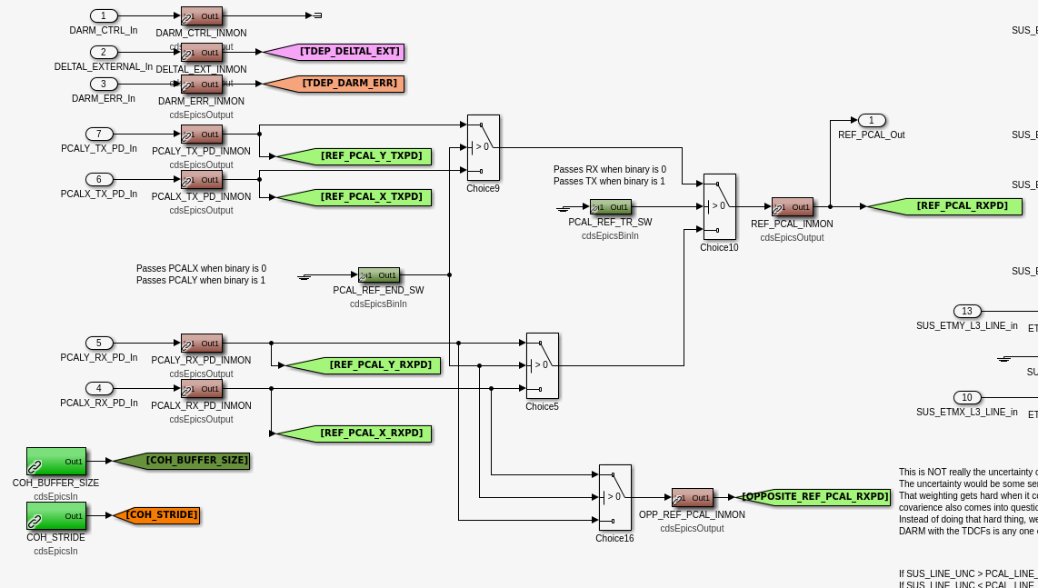
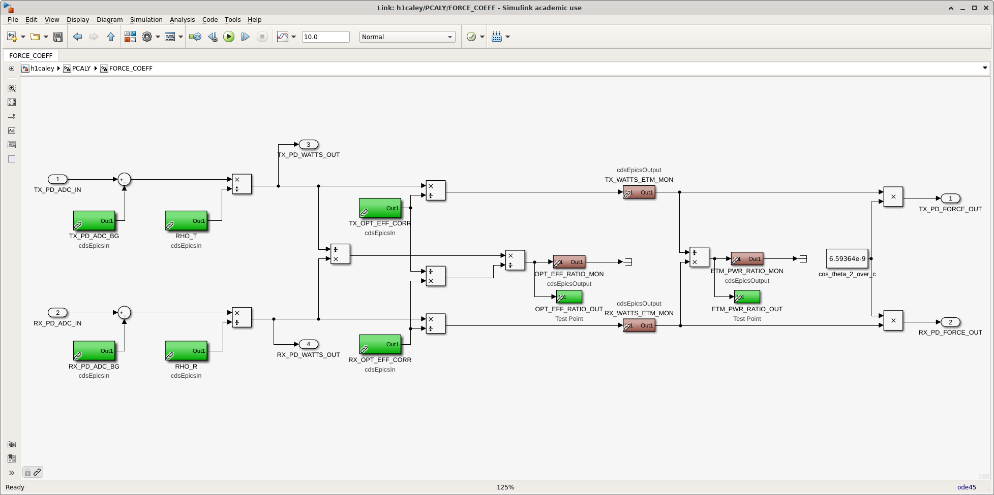
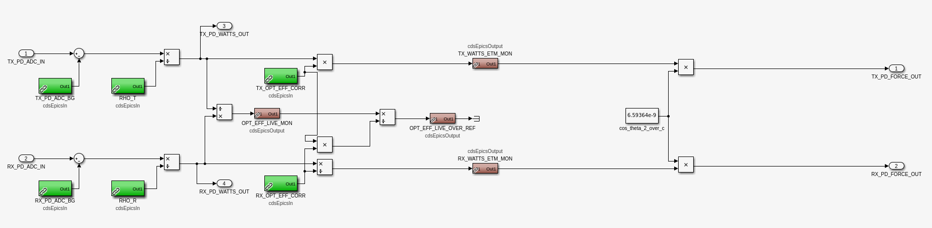
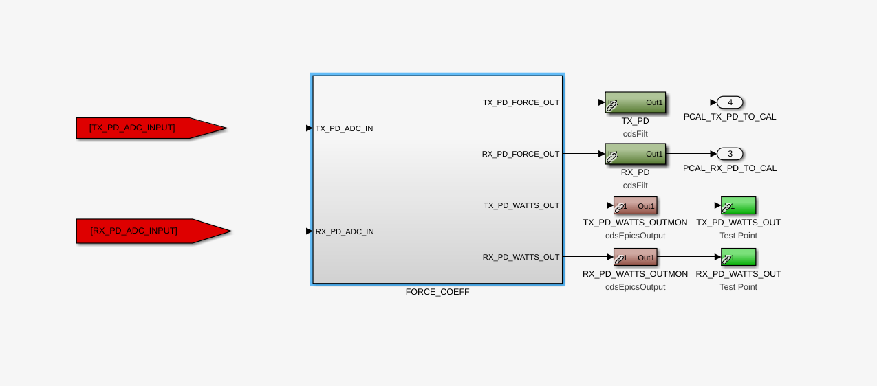
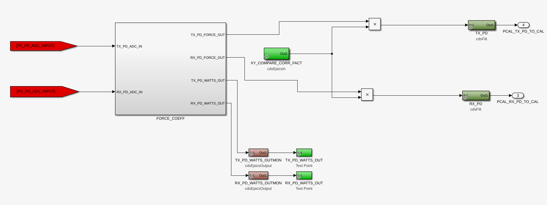
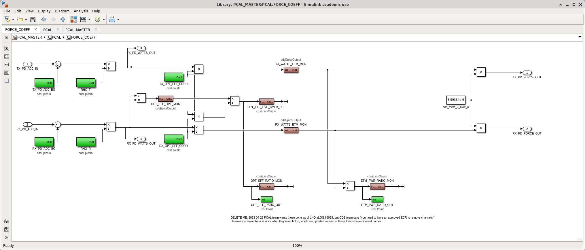
J. Kissel, D. Bhattacharjee, T. Sanchez, J. Betzwieser WP 11138 From LLO:64213, I'm importing three changes to, and one feature removal from, the PCAL end-station calculations to compute the representative force and corresponding displacement for each channel, updating them for the latest methodology the team wishes to use in O4. Within the force calculation block this includes: (1) Correcting an inconvenience an EPICs record set in the computation of force coefficient, where the reference optical efficiency for the RX and TX PDs are stored. Where before the RX and TX optical efficiency EPICs records (TX_OPT_EFF_CORR and RX_OPT_EFF_CORR) were divided into each channels path, now, the TX record is multiplied in and the RX record remains divided in to each respective channel. (2) The calculation of optical efficiency *ratio* (comparing the ratio of TX to RX, then normalized by the above reference values) has been re-arranged, with an additional EPICs monitor of the unnormalized ratio for better understanding. Note: this causes a channel name change -- formerly, the normalized ratio was called OPT_EFF_RATIO_MON, and now it's called OPT_EFF_LIVE_OVER_REF. The new channel monitoring the unnormalized ratio is called OPT_EFF_LIVE_MON. (3) The former monitor of the ratio between channels was taken *after* this optical efficiency correction, with an EPICs and test point channel called ETM_PWR_RATIO_MON and ETM_PWR_RATIO_OUT. These have been unceremoniously removed. See before vs. after screenshots. Outside the force calculation, just prior to the conversion to displacement in the TX_PD and RX_PD filter banks, there's now a new EPICs record that applies the multiplicative correction to account for the differences in displacement between the X and Y arm, informed by the side-by-side comparison between the answer as seen in DARM. This new record is XY_COMPARE_CORR_FACT. See before vs. after screenshots. To import these changes was relatively simple, just an svn up to /opt/rtcds/userapps/release/cal/common/models PCAL_MASTER.mdl The h1calex and h1caley models, with the following updated library part, have been built successfully in prep for tomorrow's install and restart. I'll update MEDM screens tomorrow.
The CDS team informs me that it's been recently decreed that "no channels shall be removed without ECR," so I've reverted the removal of the OPT_EFF_RATIO_MON, OPT_EFF_RATIO_OUT, ETM_PWR_RATIO_MON, ETM_PWR_RATIO_OUT channels since the PCAL team doesn't have an ECR for these changes. All other infrastructure that rearranges the calculation and adds new channels will still go in as described above. See new screenshot of the FORCE_COEFF block. Here's the official channel change list for these changes jeffrey.kissel@cdsws03:~$ check_model_daq_configuration h1calex --------------------- file times ---------------------- Tue Apr 25 07:54:43 2023 = Model build time Tue Apr 18 10:21:21 2023 = Current configuration load time DAQ configuration is changed, processing... ++: slow channel H1:CAL-PCALX_FORCE_COEFF_OPT_EFF_LIVE_OVER_REF added to the DAQ ++: slow channel H1:CAL-PCALX_FORCE_COEFF_OPT_EFF_LIVE_MON added to the DAQ ++: slow channel H1:CAL-PCALX_XY_COMPARE_CORR_FACT added to the DAQ Total number of DAQ changes = 3 (3 additions, 0 deletions) jeffrey.kissel@cdsws03:~$ check_model_daq_configuration h1caley --------------------- file times ---------------------- Tue Apr 25 07:59:02 2023 = Model build time Tue Apr 18 10:21:21 2023 = Current configuration load time DAQ configuration is changed, processing... ++: slow channel H1:CAL-PCALY_FORCE_COEFF_OPT_EFF_LIVE_OVER_REF added to the DAQ ++: slow channel H1:CAL-PCALY_FORCE_COEFF_OPT_EFF_LIVE_MON added to the DAQ ++: slow channel H1:CAL-PCALY_XY_COMPARE_CORR_FACT added to the DAQ Total number of DAQ changes = 3 (3 additions, 0 deletions) which all match the functional changes expected from above.
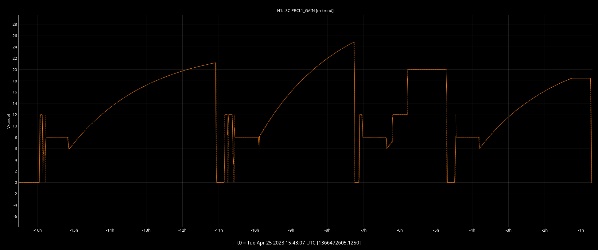
Wrote a new guardian called THERMALIZATION. FOr now it will only change the PRCL gain following a tyrend close to what we measured over past locks.
The plan is that ISC_LOCK will request the "THERMALIZED" state after LOWNOISE_LENGTH_CONTROL, instead of turning on the PRCL UGF servo.
The THERMNALIZATION guardian will transition to "SERVO_PRCL_GAIN" and start increasing the PRCL gain (with 30s ramp) following the equation:
H1:LSC-PRCL1_GAIN = [Gain set in LOWNOISE_LENGTH_CONTROL] * SCALE
SCALE = 1 + 3*(1 - exp(- time / 7800))
After 6 hours the THERMALIZATION guardian will stop adjusting the gain and go to "THERMALIZED"
We still need to test this new guardian at the next lock acquisition
The new hard-coded adjustment of the PRCL gain worked almost correctly. During one lock the initial gain was incorrectly set to 8 instead of 6. This probably happenend becvause the THERMALIZATION guardian read the PRCL1 gain too early after ISC_LOCK changed from 8 to 6.
I added a 10 seconds wait in the main() function of the SERVO_PRCL_GAIN to avoid this problem in the future.
As reported before, we see very often bumps in DARM spaced at 4.05 Hz.
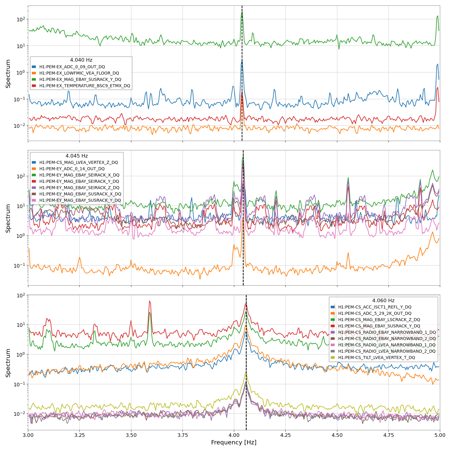
I wrote a script to look at all 6000+ DQ'ed channels and look for peaks at 2 Hz and at 4 Hz. A peak is defined in this case as a spectral feature where the ratio of the ASD at 4 +- 0.3 Hz over the ASD at 4 Hz is at least 1/5.
The interesting result is that many PEM signals have a large peak at 4.05 Hz: mostly magnetometers and radio antennas, but also other PEM channels
This is the list of ALL Dq'ed channels that have a peak at 4.0x Hz:
H1:PEM-CS_ACC_ISCT1_REFL_Y_DQ 4.060 Hz
H1:PEM-CS_ADC_5_29_2K_OUT_DQ 4.060 Hz
H1:PEM-CS_MAG_EBAY_LSCRACK_Z_DQ 4.060 Hz
H1:PEM-CS_MAG_EBAY_SUSRACK_Y_DQ 4.060 Hz
H1:PEM-CS_MAG_LVEA_VERTEX_Z_DQ 4.045 Hz
H1:PEM-CS_RADIO_EBAY_NARROWBAND_1_DQ 4.060 Hz
H1:PEM-CS_RADIO_EBAY_NARROWBAND_2_DQ 4.060 Hz
H1:PEM-CS_RADIO_LVEA_NARROWBAND_1_DQ 4.060 Hz
H1:PEM-CS_RADIO_LVEA_NARROWBAND_2_DQ 4.060 Hz
H1:PEM-CS_TILT_LVEA_VERTEX_T_DQ 4.060 Hz
H1:PEM-EX_ADC_0_09_OUT_DQ 4.040 Hz
H1:PEM-EX_LOWFMIC_VEA_FLOOR_DQ 4.040 Hz
H1:PEM-EX_MAG_EBAY_SUSRACK_Y_DQ 4.040 Hz
H1:PEM-EX_TEMPERATURE_BSC9_ETMX_DQ 4.040 Hz
H1:PEM-EY_ADC_0_14_OUT_DQ 4.045 Hz
H1:PEM-EY_MAG_EBAY_SEIRACK_X_DQ 4.045 Hz
H1:PEM-EY_MAG_EBAY_SEIRACK_Y_DQ 4.045 Hz
H1:PEM-EY_MAG_EBAY_SEIRACK_Z_DQ 4.045 Hz
H1:PEM-EY_MAG_EBAY_SUSRACK_X_DQ 4.045 Hz
H1:PEM-EY_MAG_EBAY_SUSRACK_Y_DQ 4.045 Hz
Some of them have a narrow peak at 4.040 Hz, most have a narrow peak at 4.045 Hz, and a few have a broader peak at 4.06 Hz.
I could not find any change in the peak amplitudes in those channels when we see the bumps in DARM. This might suggest that 1) the peaks are a coincidence 2) there is some non-linear effect implied, for example if the radio antennas are measuring noise around some VCO frequency, and the VCO drift around and downconvert the noise from time to time.
Adrian, Robert
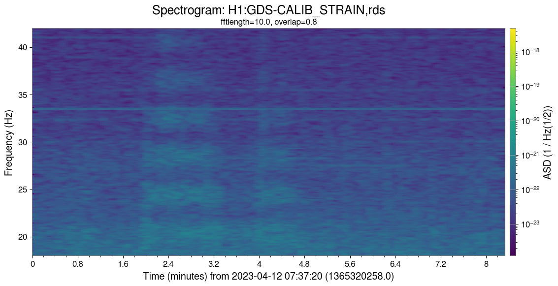
I looked at one of the "STRONG" times noted in your previous aLog. I see the harmonics of the 4 Hz bumps in a spectrogram of the strain at about +2 minutes in the attached image, but I do not see corresponding bumps in speectrograms of these channels - these can be found in the zip file attached. Many of these channels are marked as disconnected on the latest LIGOCAM run - see the attached screenshot. The 4 Hz peaks in the PEM channels are probably coincidental unless they are wiitnessing a DAQ issue that also affects controls channels.
I took a look at the ASD of EX Floor magnetometer and compared it to a couple magnetometers that are marked as working. The ASD does look flatter and lower magnitude than working magnetometers.
An easy way I used to check magnetometers was to wave a fridge magnet near the magnetometer while monitoring the current power spectrum on a laptop.