TJ, Camilla WP #12831
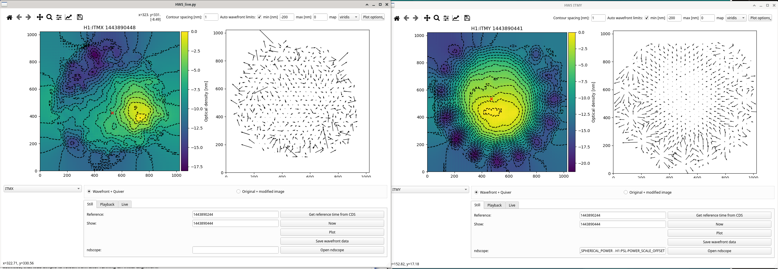
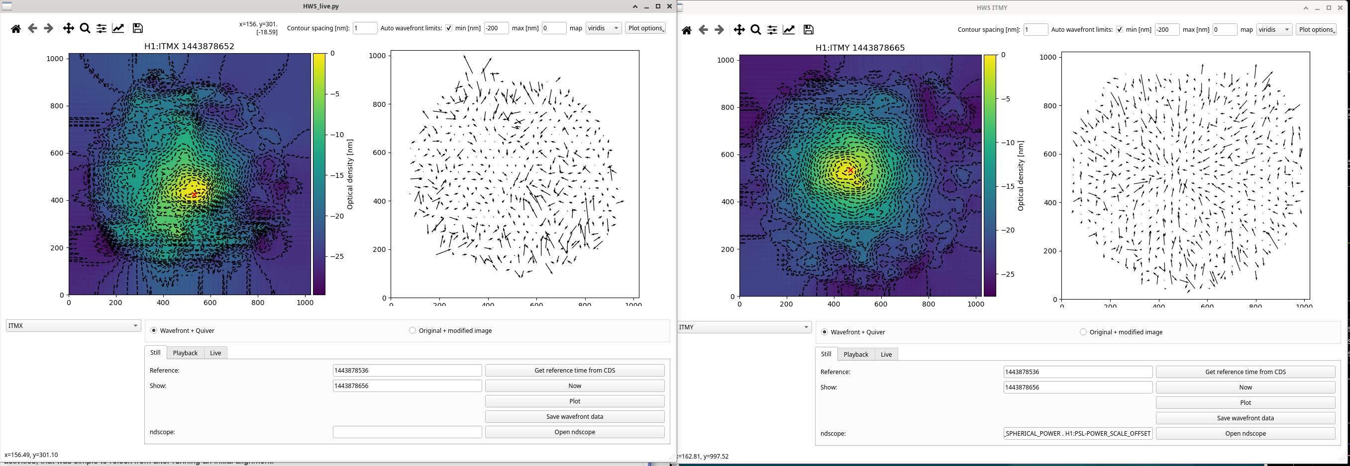
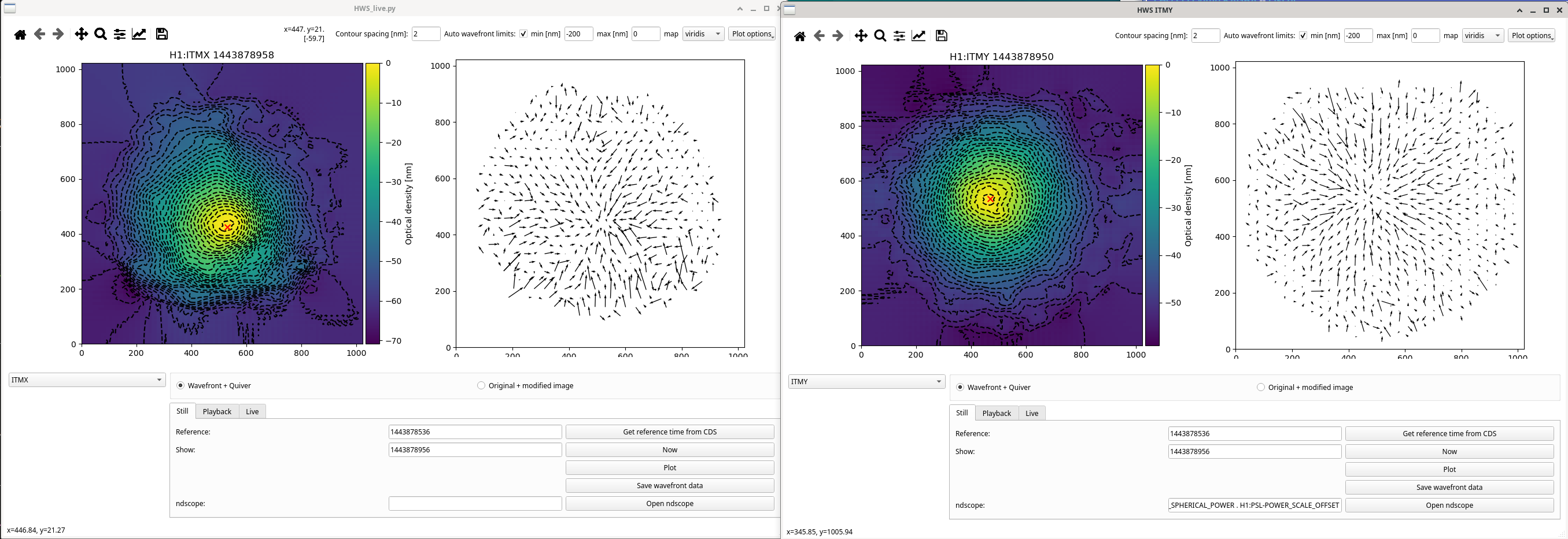
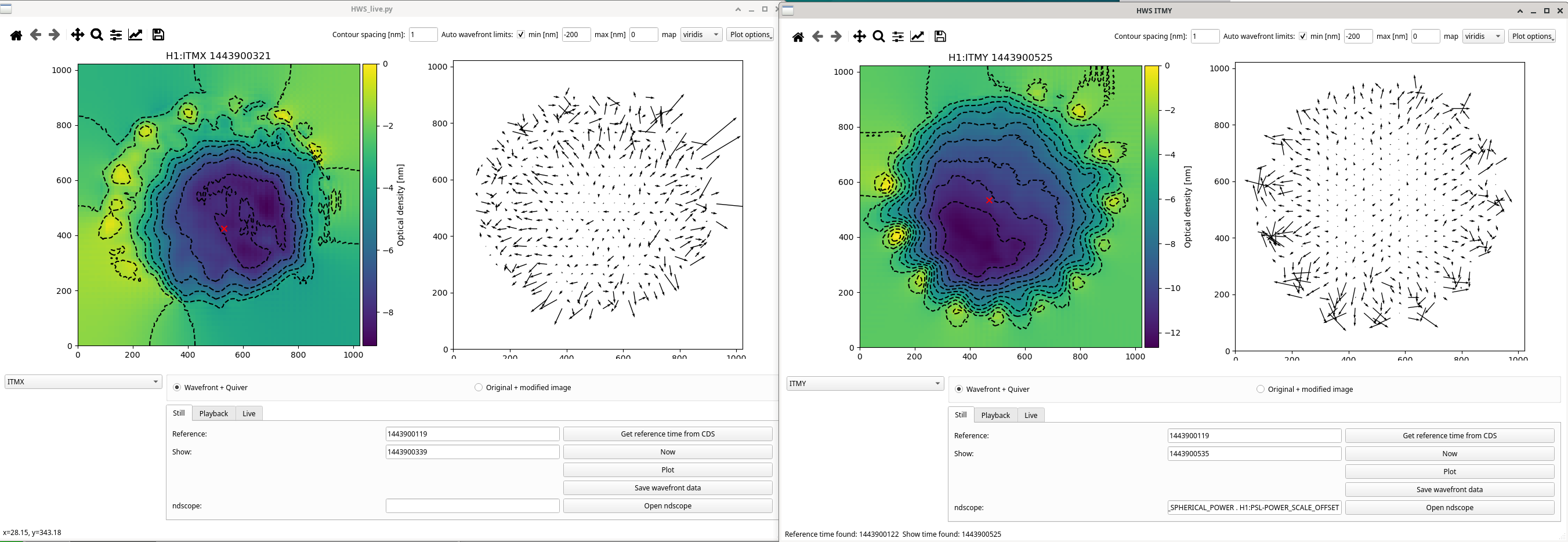
As it's been noted by the operators 87315 and we saw confusing HWS Live results 87341, today we swapped the ITMX HWS SLED, leaving ITMY as the signal appears stronger and we hope will last to the end of the run.
Last swapped in May 84417, so this degraded quicker than usual.
Following the T1500193 procedure, and started the code back up with fresh references while we were in maintenance still.
- HWS starting values
- Power as measured from fiber launcher: IX 0.7mW IY 0.8mW
- ITMX SLED removed - https://ics.ligo-la.caltech.edu/JIRA/browse/QSDM-790-5--00-11.21.382
- HWS ending values
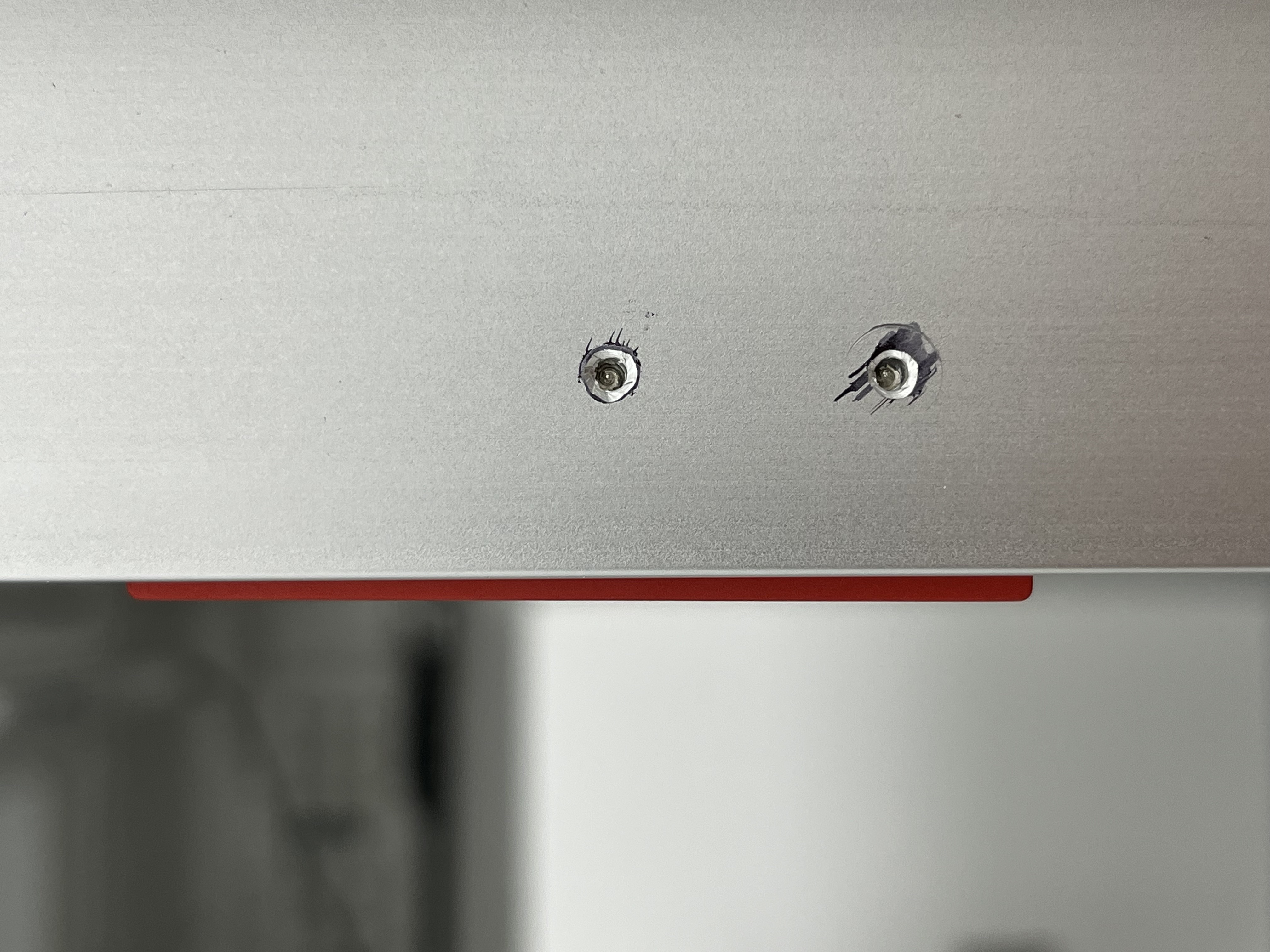
- ITMX SLED installed: https://ics.ligo-la.caltech.edu/JIRA/browse/QSDM-790-5--00-01.24.077 2.5mW = 120mA = 480mV (on TP with 250mA/V) Max current set to 114mA
- Power as measured from fiber launcher: IX 3.0mW IY 1.0mW (unsure why it increased)
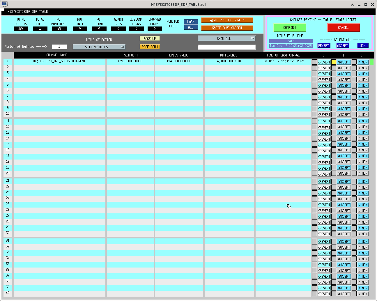
In the past we've calibrated H1:TCS-ITM{X,Y}_HWS_SLEDPOWERMON channel, but we didn't do this today. SDF screenshot attached of the new current limit.
Increased both ITMX and ITMY camera frame rate frequencies from 1Hz to 4Hz which is the lowest possible frequency without any saturated pixels.
When looking at the streamed images, I noticed there was some leakage, mainly of the ITMX beam into the ITMY camera.
| Avg. Pixel Value of ITMX CCD | Avg. Pixel Value of ITMY CCD | |
| Both SLEDs on | 162 | 246 |
| Both SLEDs off | 0 | 0 |
| ITMX only on | 161 | 65 |
| ITMY only on | 0 | 234 |
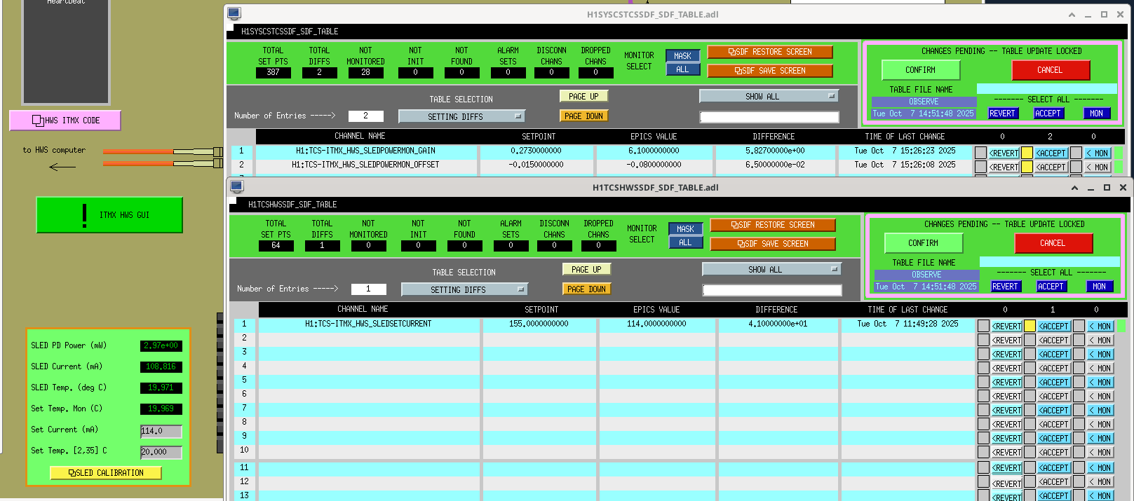
Calibrated the ITMX SLED while others were fixing some SQZ issues. SDF values attached.

