TITLE: 10/15 Day Shift: 1430-2330 UTC (0730-1630 PST), all times posted in UTC
STATE of H1: Observing at 150Mpc
OUTGOING OPERATOR: Ibrahim
CURRENT ENVIRONMENT:
SEI_ENV state: CALM
Wind: 0mph Gusts, 0mph 3min avg
Primary useism: 0.08 μm/s
Secondary useism: 0.13 μm/s
QUICK SUMMARY:
- 14:00 UTC Observing
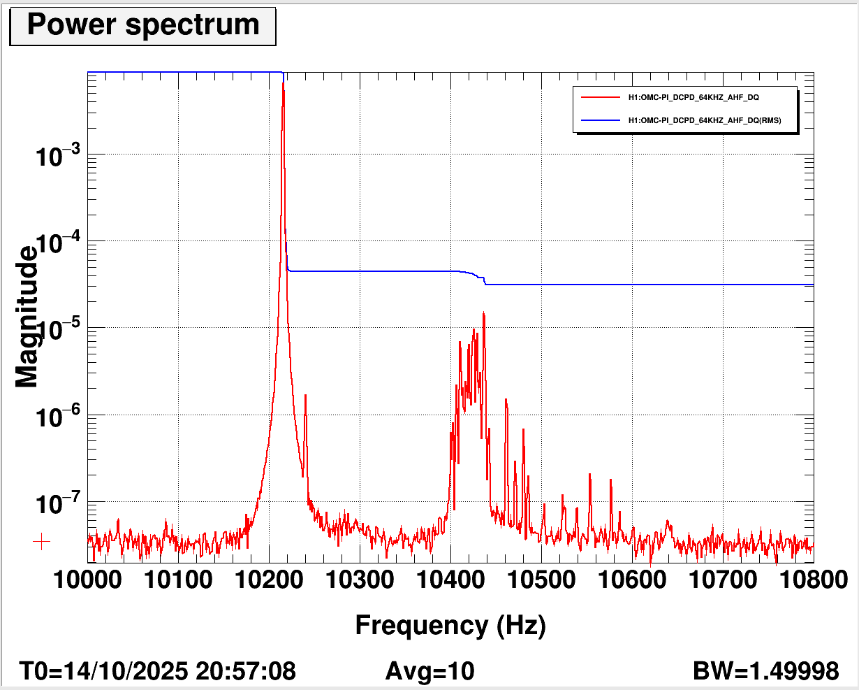
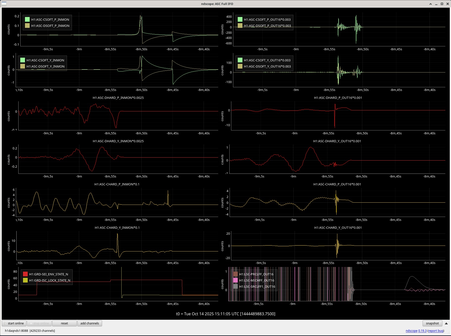
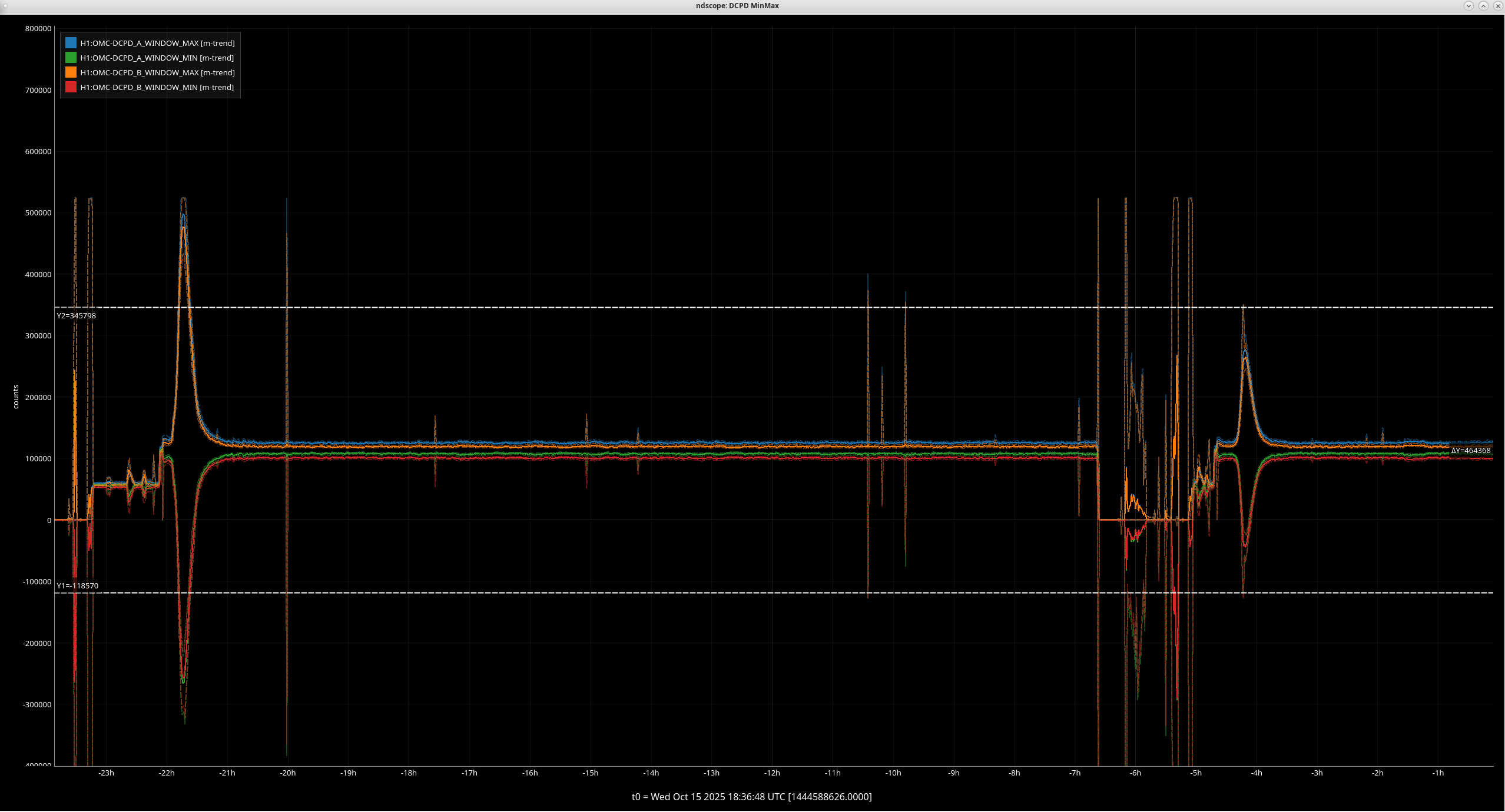
- DCPD window shows something ringup then damp back down in the past 15 minutes, Transient PI? It was smaller than we saw yesterday (added plot at 18:39)
- 14:17 UTC GRD-Short E610359
- Secondary microseism continues to decrease, low winds
- Lockloss doesn't seem to be updating, the most recent one isn't showing up
- The web site says: online last update: 1076.1 min ago (2025-10-14 13:42:18.164546)
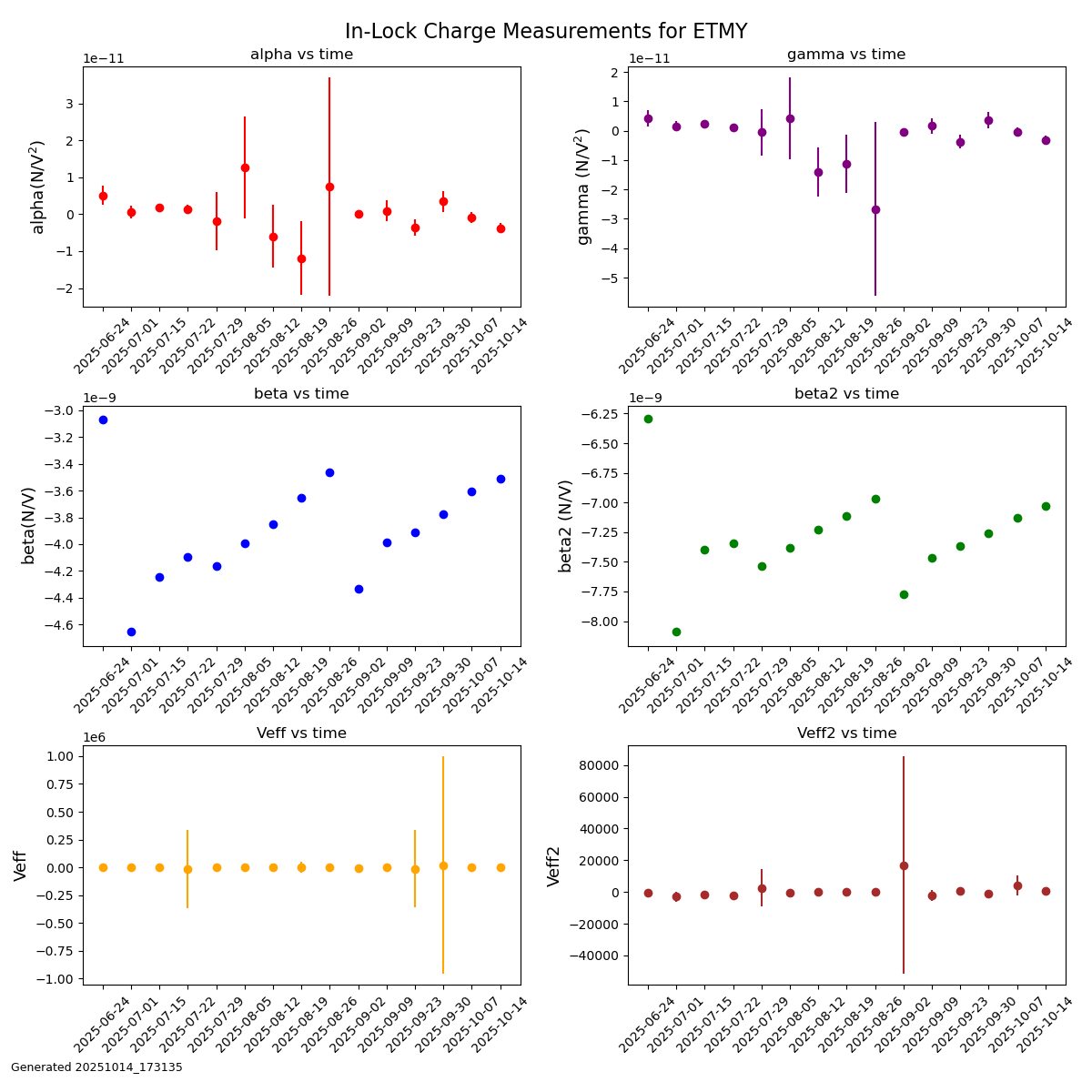
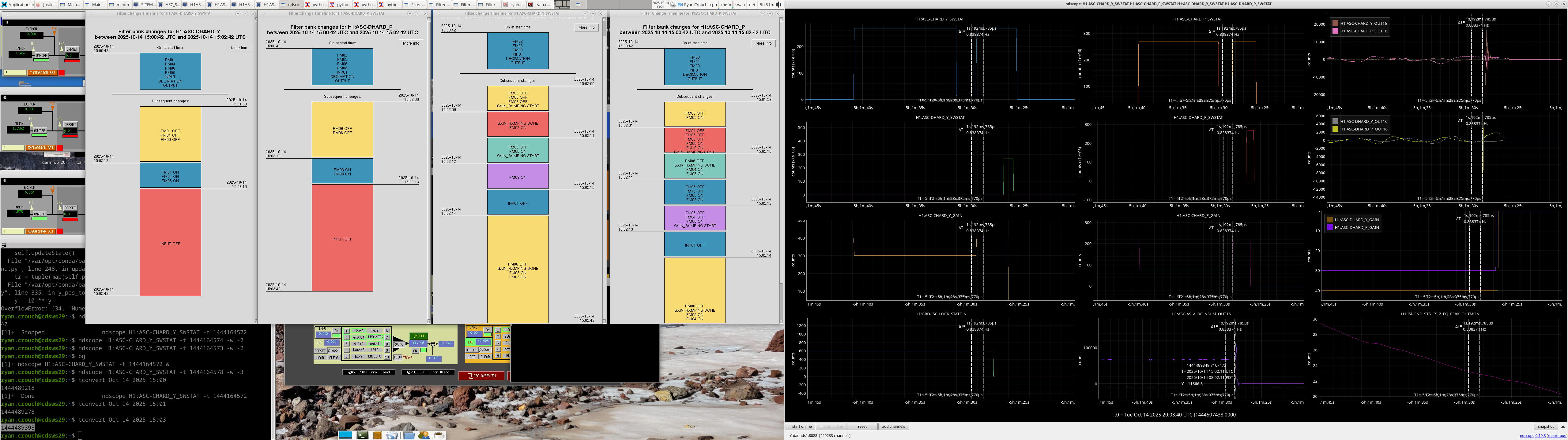
It looks like the same PI that rung up yesterday and almost caused a lockloss is still ringing up, although not as strongly. This suggests, along with other evidence, that we are still not at the right beam position on ETMY. This is on the to-do list to investigate tomorrow, and hopefully we will stop ringing up this PI. See 87473.
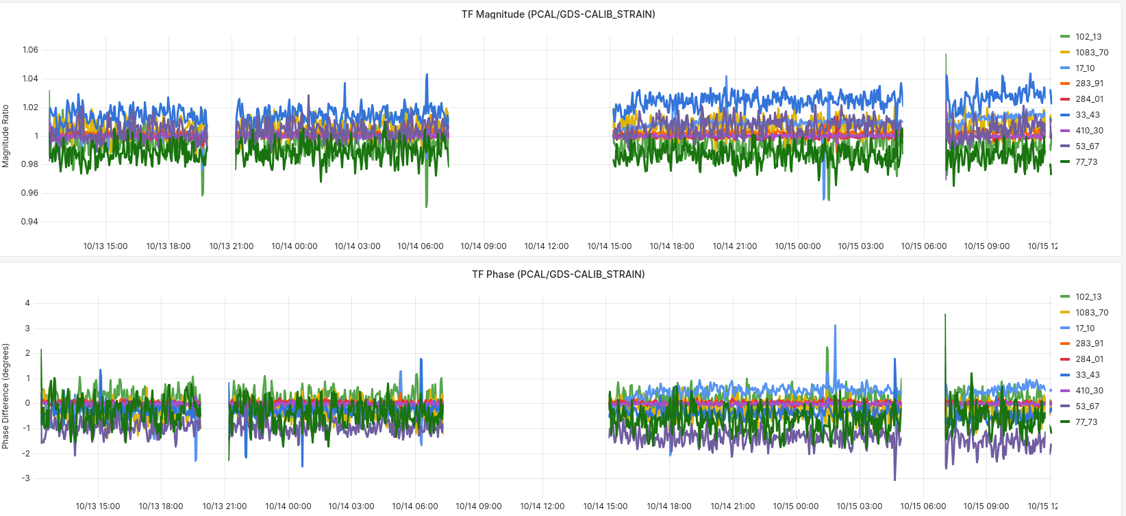
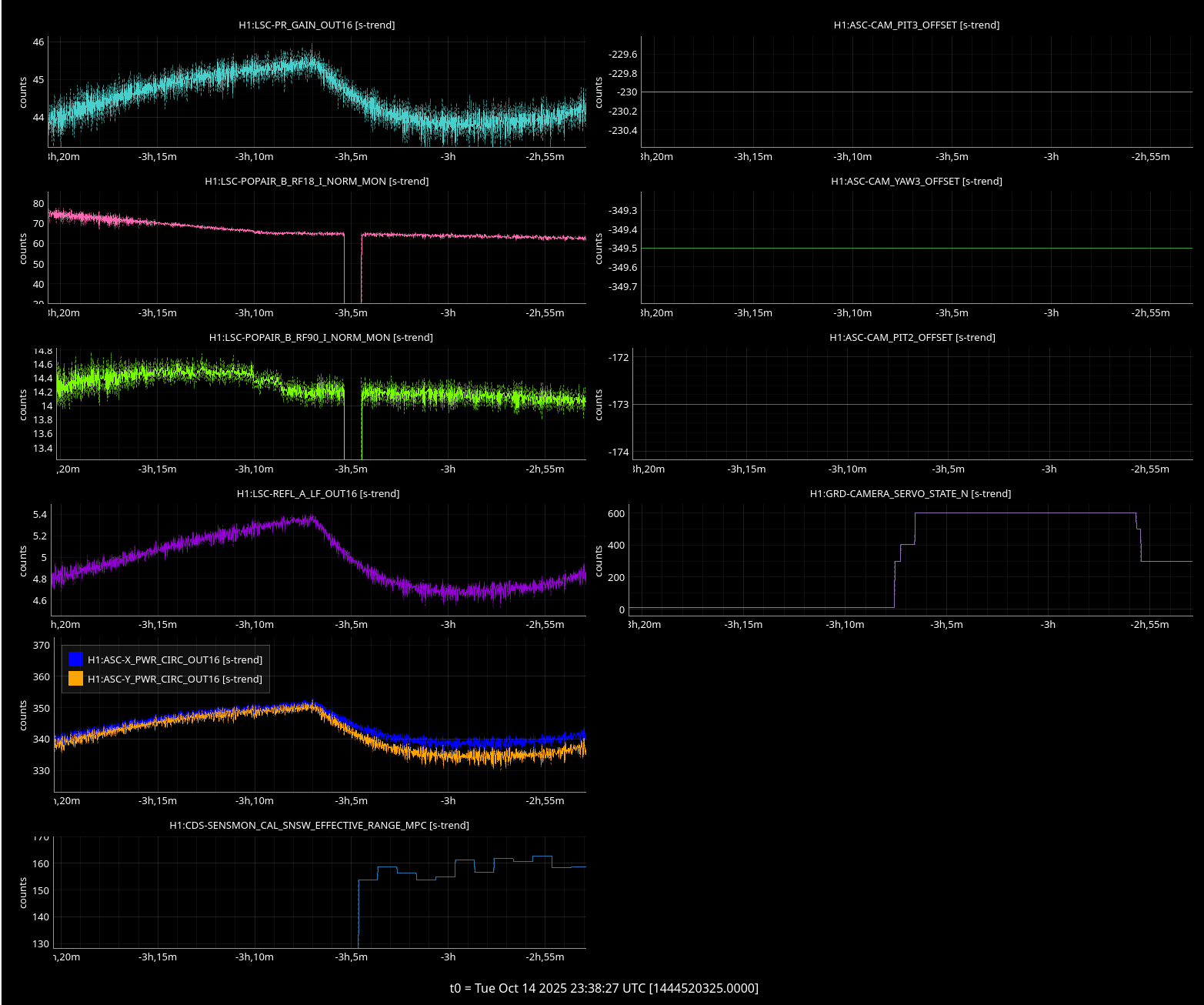
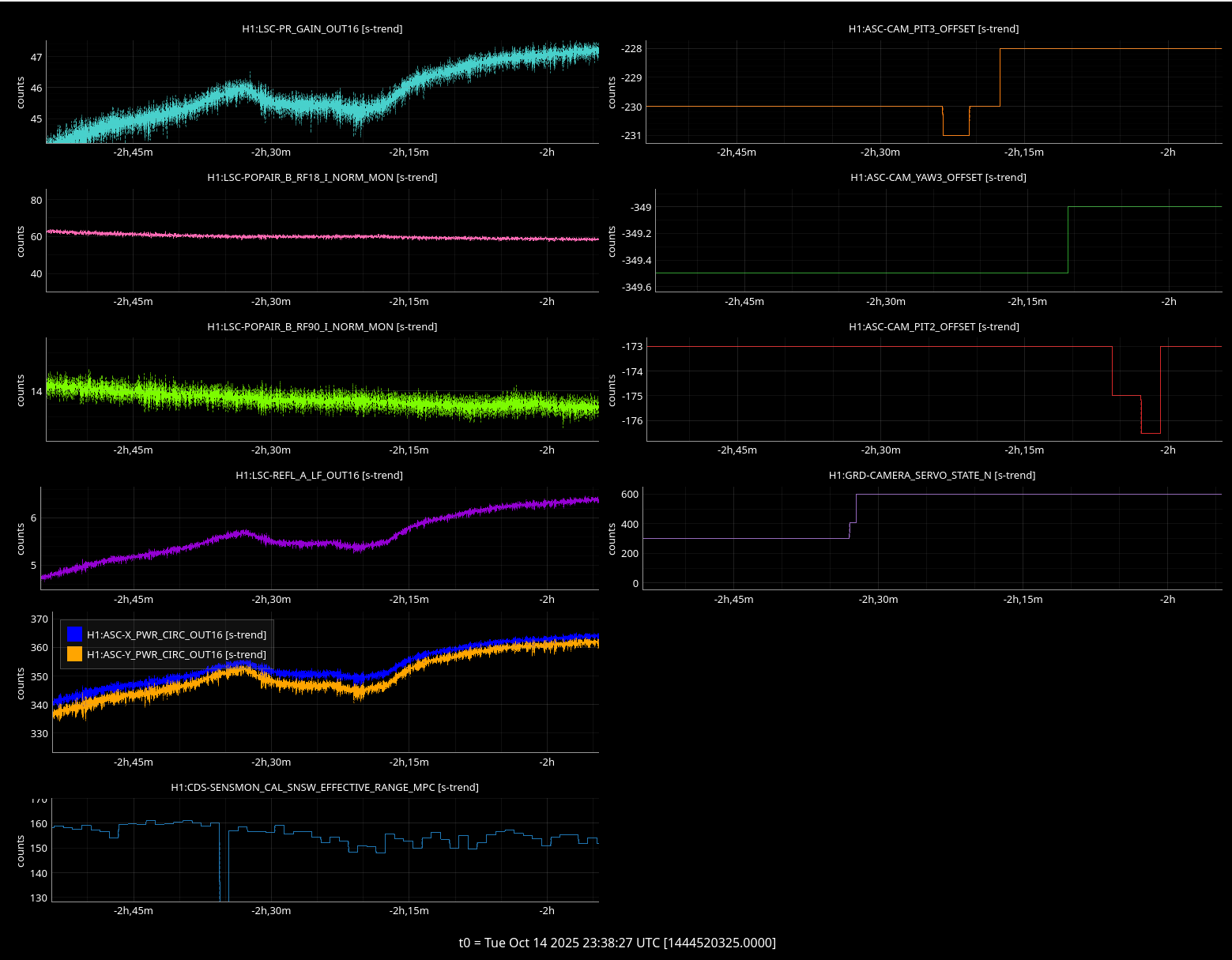
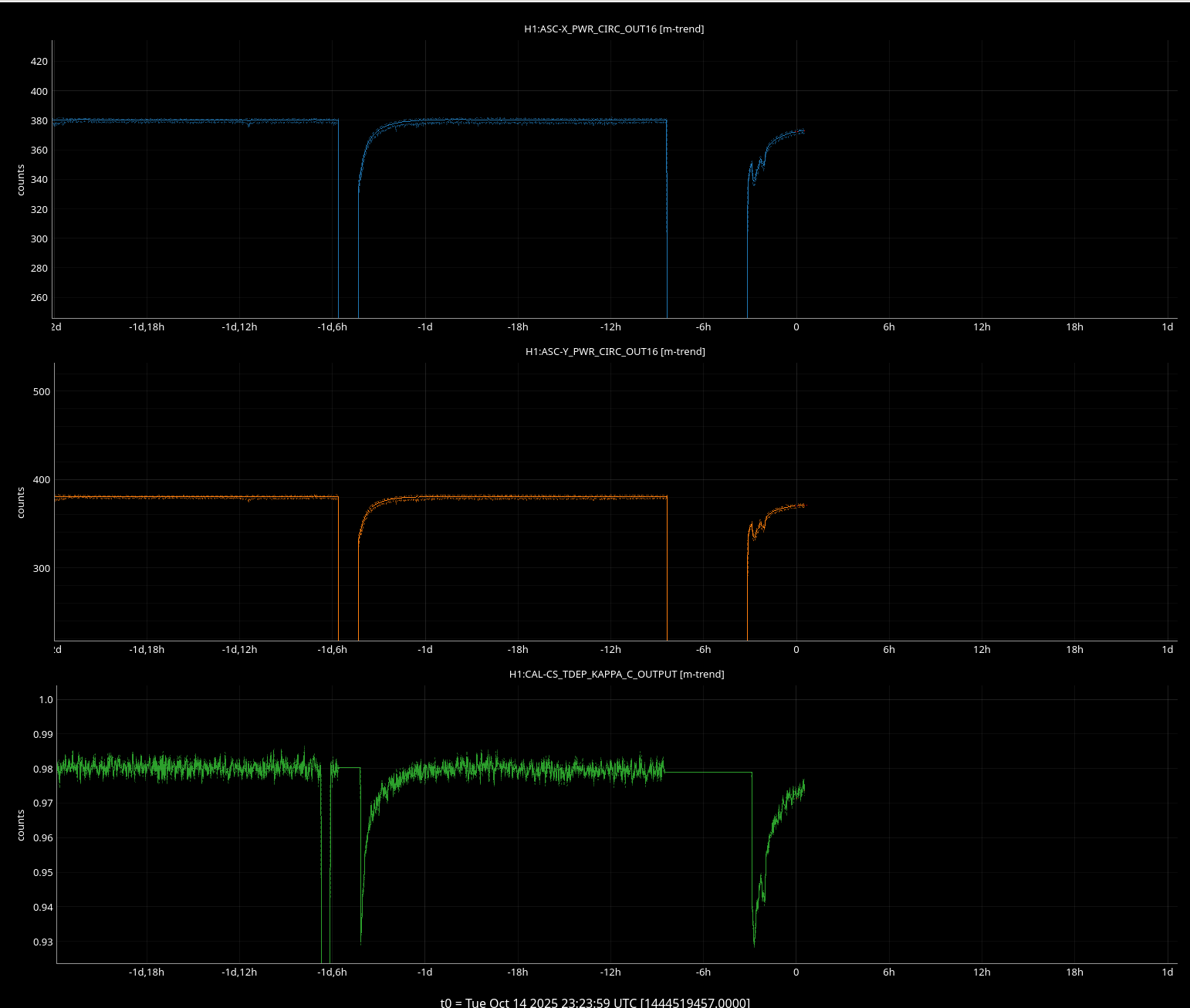
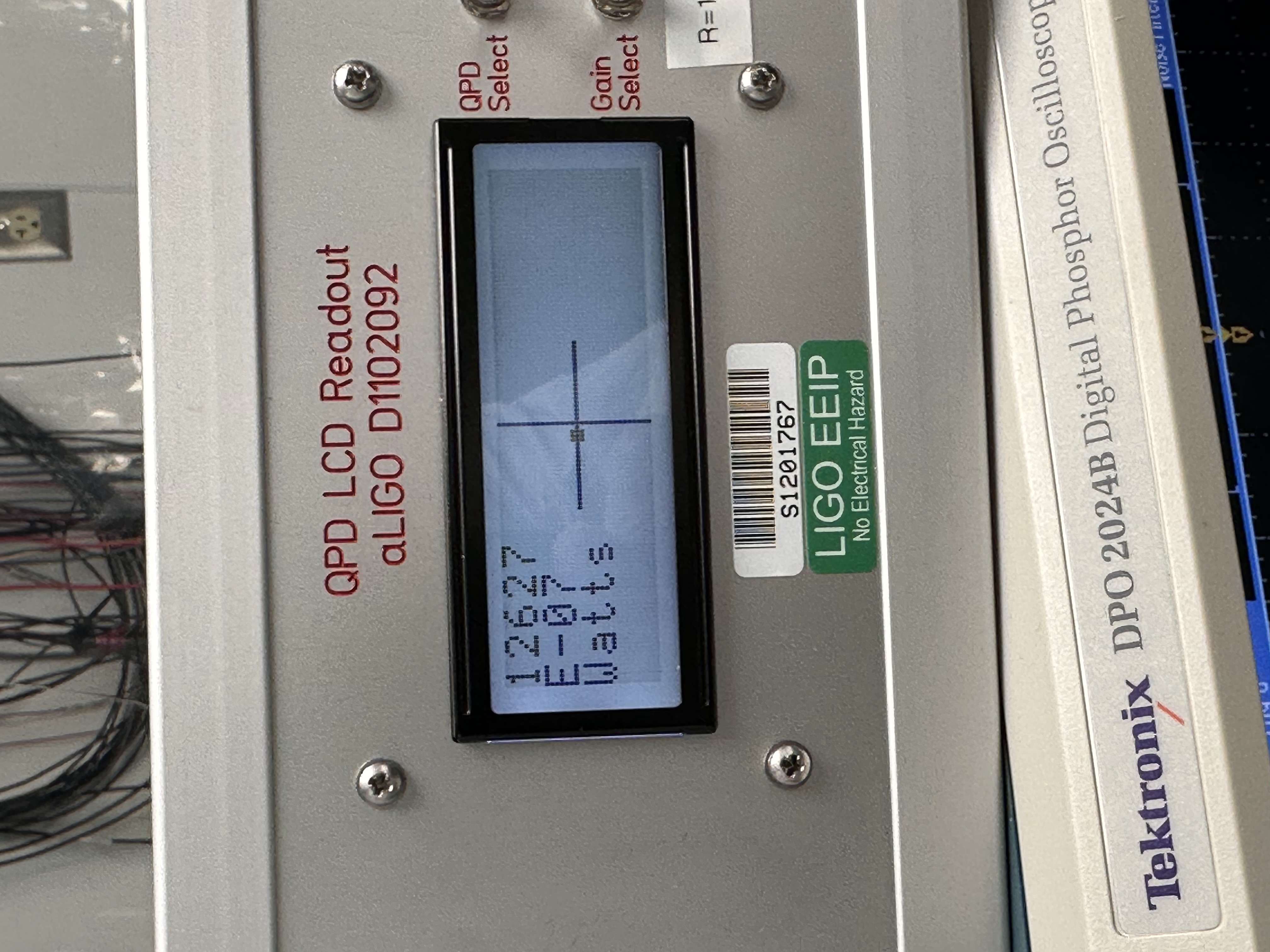
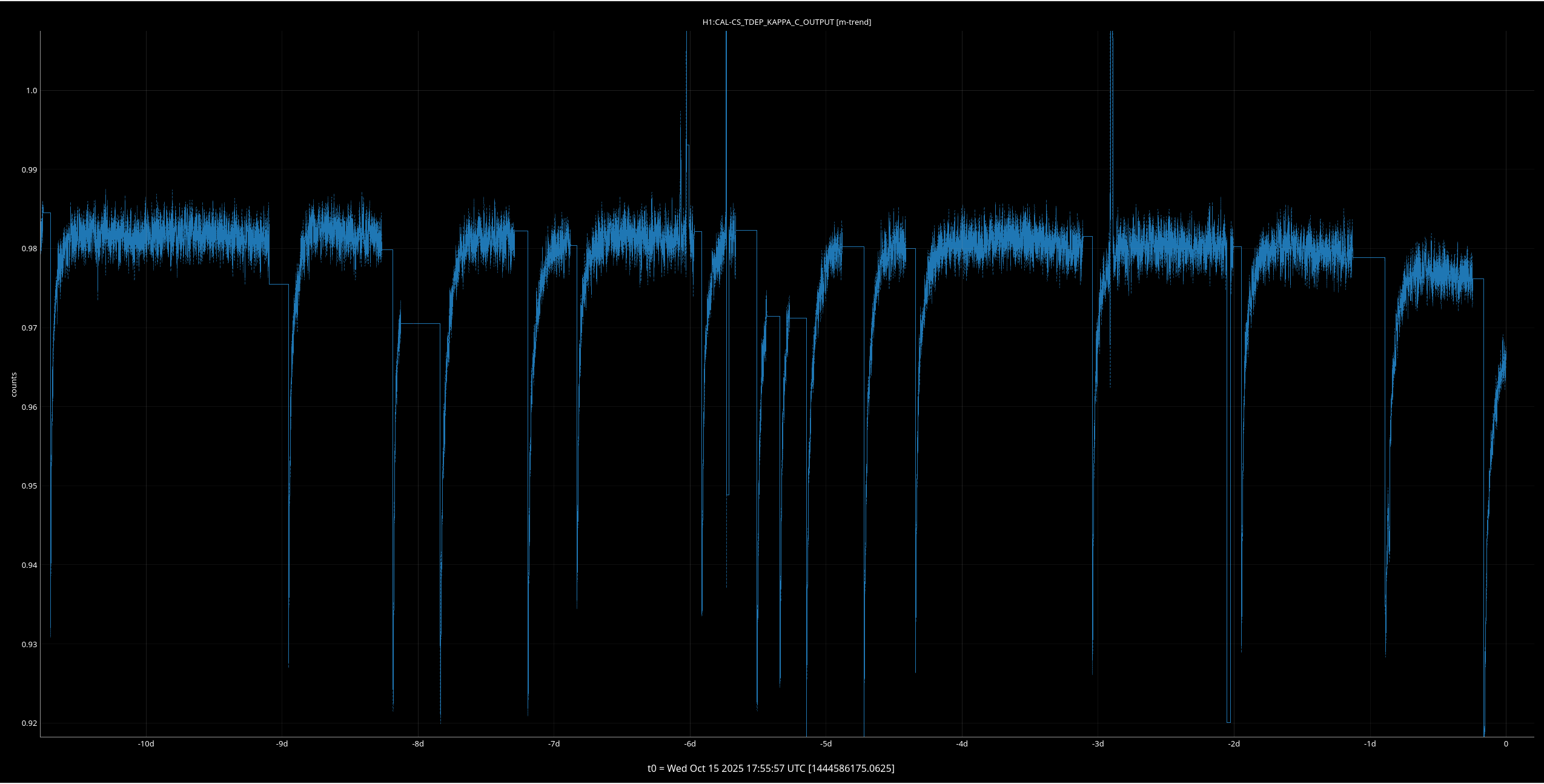
The circulating power looks lower than the previous weeks locks, kappa_c also looks lower this lock.
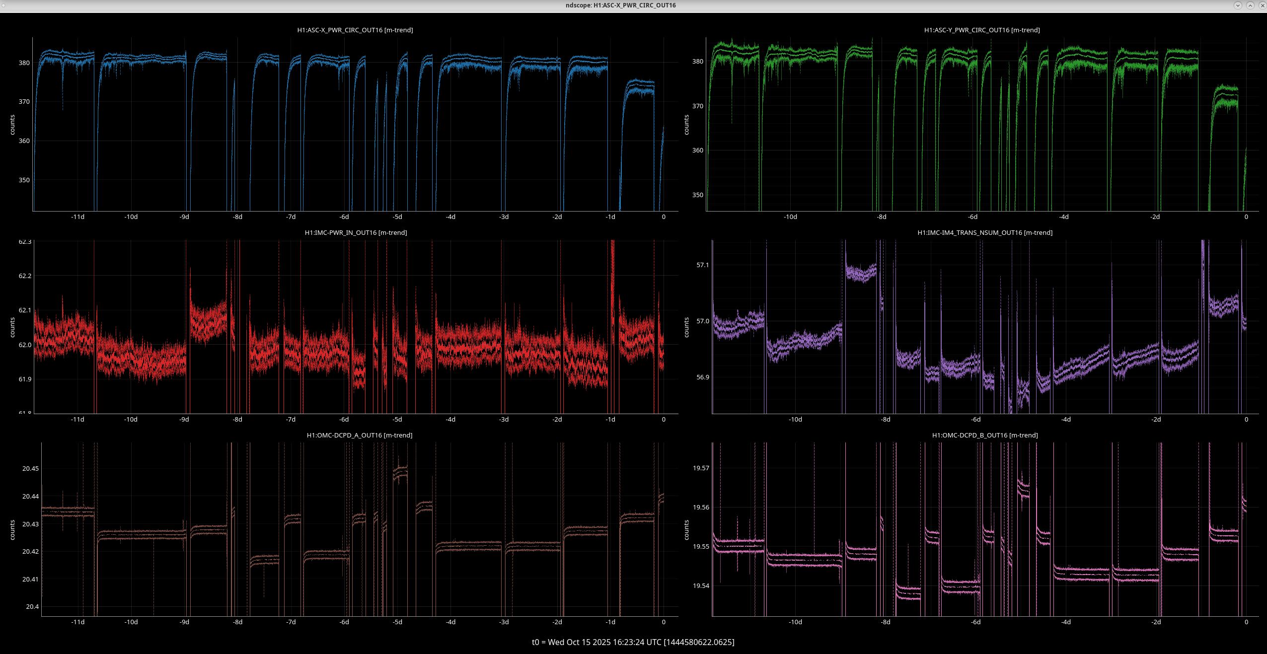
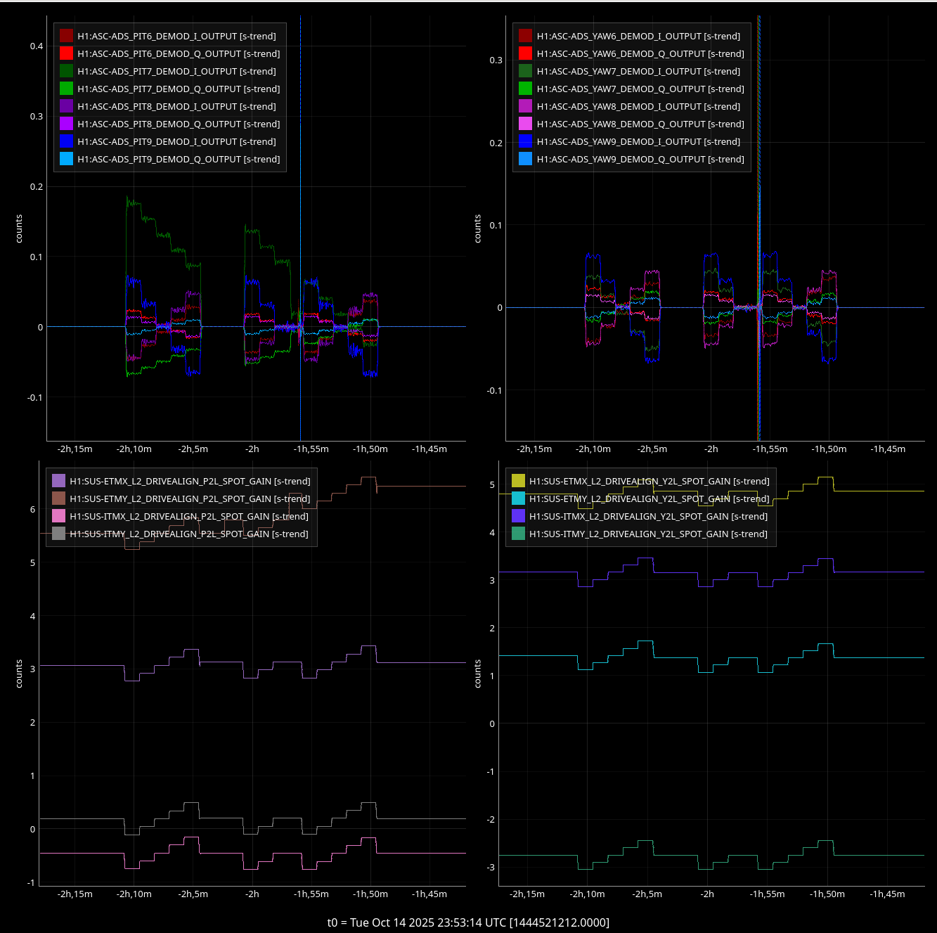
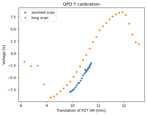
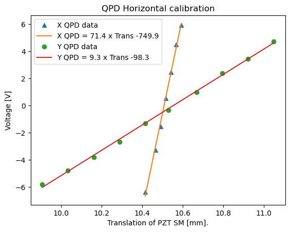
Ryan's data above in consistent with what we saw yesterday too. This makes me think that we should readjust the spot before running the calibration measurement tomorrow.
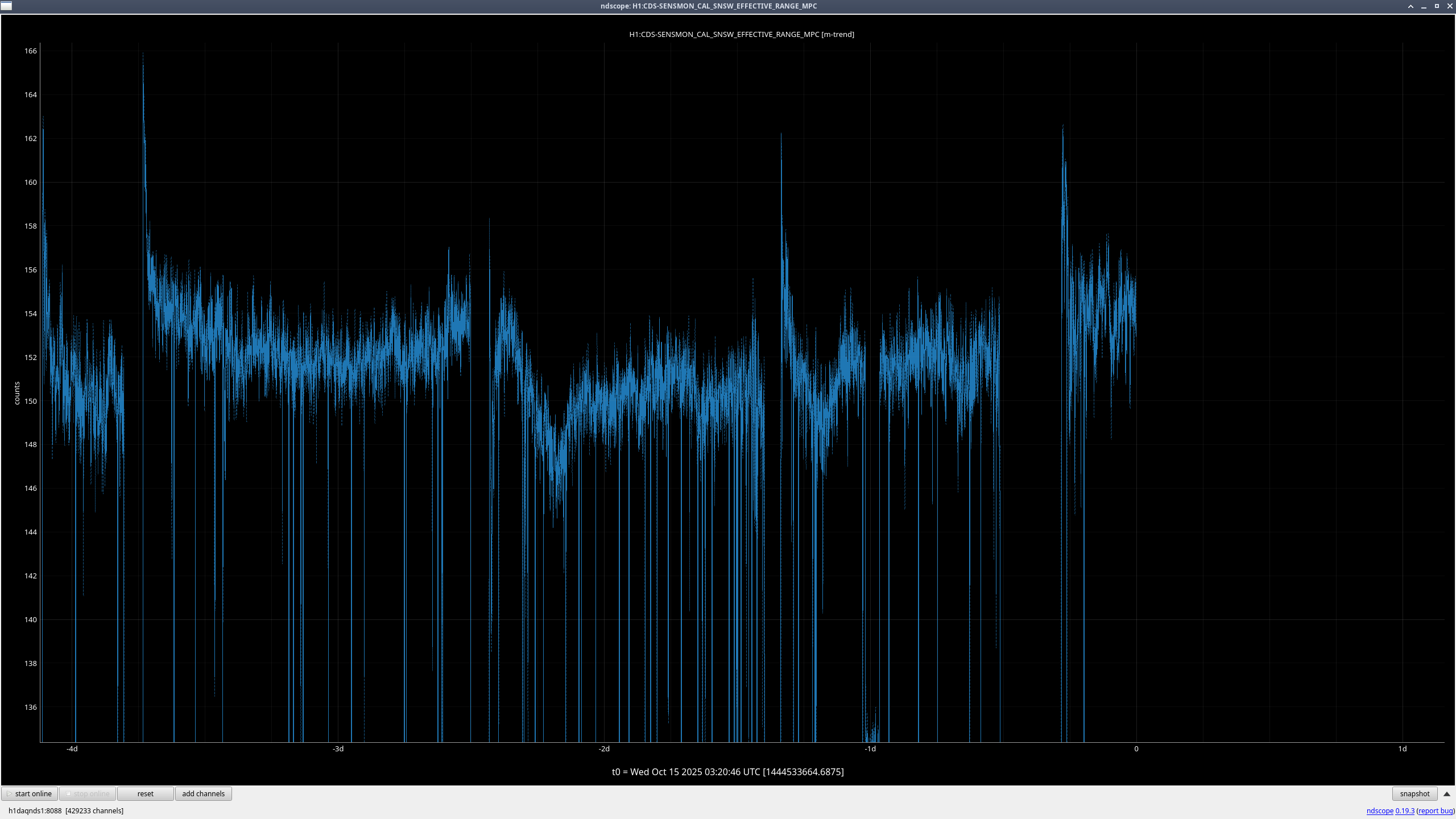
I ran the range comparison against a lock last week with better range, lot of extra low frequency noise.

We did not load the camera servo guardian yesterday after the changes, so the new camera offsets did not get properly loaded and engaged when the camera servos came on. We are back at the old camera offsets for ETMY, but at new A2L gains based on where we set the camera offsets yesterday. So, the buildups are bad because we're at the wrong beamspot on EY, and the sensitivity is bad because the beam spot is not lined up with the mirror actuation point, so we have extra ASC coupling, as Ryan's plot above shows.
Neither the A2L gains nor the camera offsets are monitored in SDF, so this was not caught until just now.
Calibration monitoring line at 33 Hz was also 1% worse than yesterday.