TITLE: 11/19 Eve Shift: 00:00-08:00 UTC (16:00-00:00 PST), all times posted in UTC
STATE of H1: Observing at 113Mpc
OUTGOING OPERATOR: Camilla
CURRENT ENVIRONMENT:
SEI_CONF state: WINDY
Wind: 4mph Gusts, 3mph 5min avg
Primary useism: 0.03 μm/s
Secondary useism: 0.28 μm/s
QUICK SUMMARY:
First of all, thank you CAmilla ad TJ for handling my duties because of my late arrival.
H1 locked and observing for approx 2.5 hours
TITLE: 11/19 Day Shift: 16:00-00:00 UTC (08:00-16:00 PST), all times posted in UTC
STATE of H1: Observing at 114Mpc
INCOMING OPERATOR: Ed
SHIFT SUMMARY: Lost lock and took a while to get it back, unsure why.
LOG:
It seems that the range drop which happened on Friday is closely realted to the range drops we had been seeing before Daneil and Nutsinee lowered the CLF power (see comments on 52984)
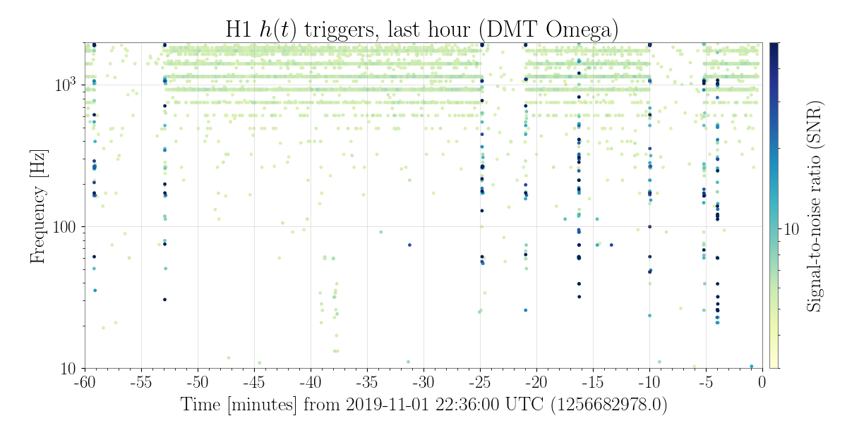
We still see the distinctive low SNR lines of high frequency glitches in the control room glitch monitor, (although they seem less loud now), which previously were shown to go away when the squeezer was blocked (image) It seems that our glitch rate since friday has been just about 1/second of SNR 5 glitches, which is a bit lower than what we saw previously when the range dropped, but higher that the previously quiet state (compare today to Nov 8)
Since the CLF was lowered Nov 8th, we have continued to see a correlation of jumps in the now disconnected channel H1:ISC-RF_C_SQZAOM200M_OUTPUTMON and range jumps, although it isn't a consistent relationship (similar to what was seen in 53096) The attached screenshot shows that there was a change in the behavoir of this channel friday during the time when the range dropped and it has been more stable since then (but seemingly stable in the state that is correlated with worse shot noise in the IFO).
Some tests we could think of trying would be to lower the CLF power, adjust the waveplate to keep the CLF power the same while changing the AOM drive, or disabling the ISS on the CLF.
Any insights from hveto, lasso, or other detchar people and tools could be helpful.
After yesterday's maintence time the range has been back in the 117 MPc range (front end range which is a bit higher than GDS), and the behavoir of the monitor channel for the removed 200MHz driver is still related to the range. (Screenshot attached).
Comparig the glitch rate on the summary pages for today and yesterday shows that the glitch rate is again reduced when we are in the lower range state.
Yesterday durring the maintence window Richard and I went to the racks to attempt to understand better what this channel could be connected to. We didn't do anything that should have had an impact. We did find that there were BNC T's left in the drive input channels for both of the AOM drivers used for itensity stabilization. We removed these and replaced them with the right adapters, but this should not have any impact.
Mark also spent some time trying to understand where this channel is coming from, (H1:ISC-C_RF_SQZAOM200M_OUTPUTMON), no real clues came from that.
Attached ndscope shows all TMS QPD input segments during a powerup up to our lockloss at Nov 18 2019 22:21:30 UTC.
32000 cts is the maximum our ADCs can output.
Two channels are within 1000 cts of saturating:
H1:ASC-X_TR_B_SEG1_INMON (XB1)
H1:ASC-Y_TR_B_SEG2_INMON (YB2)
This is all consistent with what our PIT YAW outputs are telling us: our QPDs are poorly aligned.
XA XB YA YB
---------------------------------
PIT 0.40 0.54 0.48 0.57
YAW 0.66 0.84 -0.47 -0.71
EDIT: We just locked again and it appears that after some thermalization YB2 is 100% touching the saturation limit. See attachment 2.
ADC overflows for the TMS QPDs YB upper left, XB upper right are overflowing during this lock. These do not seem to have an immediate effect on the interferometer: No locklosses, no immediately apparent glitches [although those might be happening, these QPDs are used for CHARD control]
Looking at whether we can align the TMS at 2 watts and trust it will be well-aligned at 38 watts input (33.5 watts on back of PRM) Seems like yes, we can align red on the TMS QPDs at 2 watts and expect it to be okay for 38 watts, as long as it's after MOVE_SPOTS. During the guardian state MOVE_SPOTS, we adjust the spots on the ITMs and to avoid our point absorbers prior to going to full power. During this stage we move significantly on our TMS QPDs, especially in pitch. Not a lock killer, but enough to saturate a segment once we reach full power. After we've reached full power, the QPD alignment continues to drift but nowhere near as significantly as the MOVE_STOPS change. If we realign the TMS to center on the QPDs after MOVE_SPOTS, I suspect our saturations will go away.
I checked the CHARD error and control signals during a time when the TRX and TRY B QPDs were saturated (now) and not saturated (early in the lock). The CHARD error signal consists of 5 PD signals for pitch, and 6 for yaw. TRY B is not one of those PDs. TRX B is. TRX B's signal is only slightly altered by the single segment saturation. (PDF 2) The normalized sum is falling as the TMS drifts further off this QPD. This causes the NSUM, PIT, and YAW ASDs to all decrease at AC. The saturated segment does not contribute at AC. Basically, our signal from this QPD is falling to zero, decreasing the overall gain of the loop. Ultimately, saturating in TRX B does not produce huge noise effects in CHARD due to the number of PDs contributing to CHARD's error signal, and the fact that TRX B's signal has not completely flatlined due to the other segments still contributing. There is a small increase in noise in pitch from 4 to 8 Hz. See PDF 1. There is effectively no increase in noise in yaw.
The primary and redundant calibration pipelines were restarted around GPS time 1258146459. The purpose of the restart was to reduce the latency, which again climbed up to ~15 seconds. In the mean time, the latency now looks normal, around 3 seconds. This seems to be a recurring problem, which we are investigating.
Camilla, Dave:
The GRB/SN external alert system had stopped running around 07:18 Sunday 17th PST. There were no logs from the lv_alert service on ext-alert to indicate a problem. Since H1 has just lost lock, I took the opportunity to restart lv_alert and the system is now updating again. The last restart of this system was last Tuesday, at 09:01 during maintenance.
~19:01 UTC. Sorry, probably should not have done this in observing. I don't think it should affect anything.
Business/ Safety items:
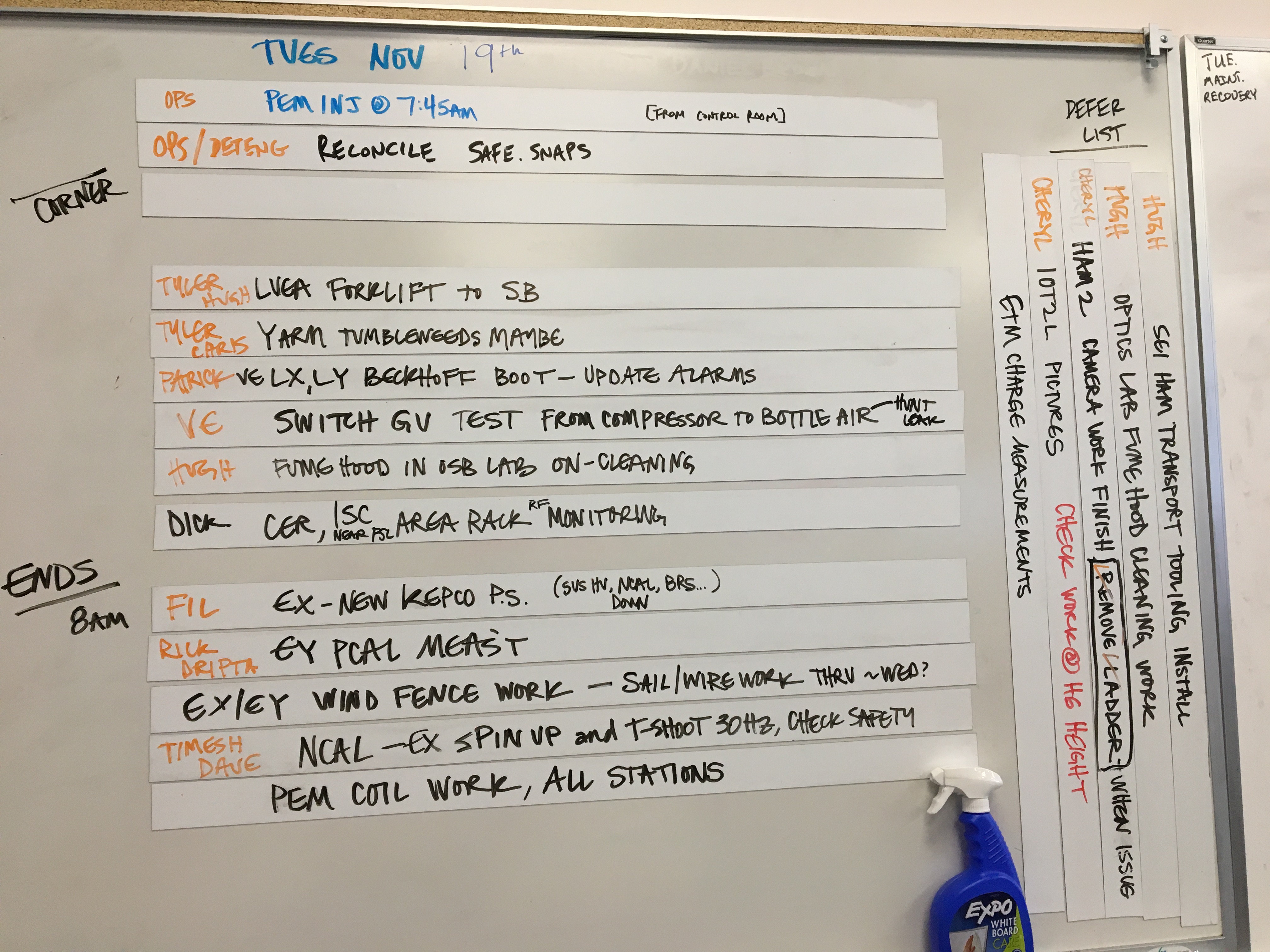
Tuesday Maintenance Activities :
See the attachment for a picture of the whiteboard
FAMIS 11518
Added no water to either chiller, both were at nominal levels. TCSX filter is still in need of replacement in the near future.
FAMIS 11039
Laser Status:
Front End Power is 32.22W (should be around 30 W)
70W Output Power is 70.37W
Front End Watch is GREEN
70W Watch is GREEN
PMC:
It has been locked 12 days, 22 hr 12 minutes (should be days/weeks)
Reflected power = 11.64Watts
Transmitted power = 52.17Watts
PowerSum = 63.81Watts.
FSS:
It has been locked for 1 days 19 hr and 15 min (should be days/weeks)
TPD[V] = 4.876V (min 0.9V)
ISS:
The diffracted power is around 2.5%
Last saturation event was 1 days 19 hours and 14 minutes ago (should be days/weeks)
Possible Issues: None
TITLE: 11/18 Owl Shift: 08:00-16:00 UTC (00:00-08:00 PST), all times posted in UTC
STATE of H1: Observing at 111Mpc
INCOMING OPERATOR: Camilla
SHIFT SUMMARY: locked in Observe
LOG:
TITLE: 11/18 Day Shift: 16:00-00:00 UTC (08:00-16:00 PST), all times posted in UTC
STATE of H1: Observing at 111Mpc
OUTGOING OPERATOR: Cheryl
CURRENT ENVIRONMENT:
SEI_CONF state: WINDY
Wind: 3mph Gusts, 2mph 5min avg
Primary useism: 0.03 μm/s
Secondary useism: 0.37 μm/s
QUICK SUMMARY: Locked for 41 hours. Expecting the wind fence crew to be on site later, tensioning the wires.
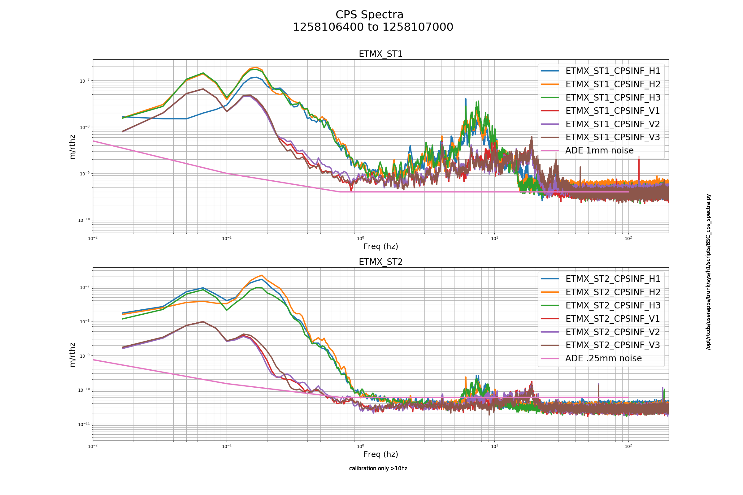
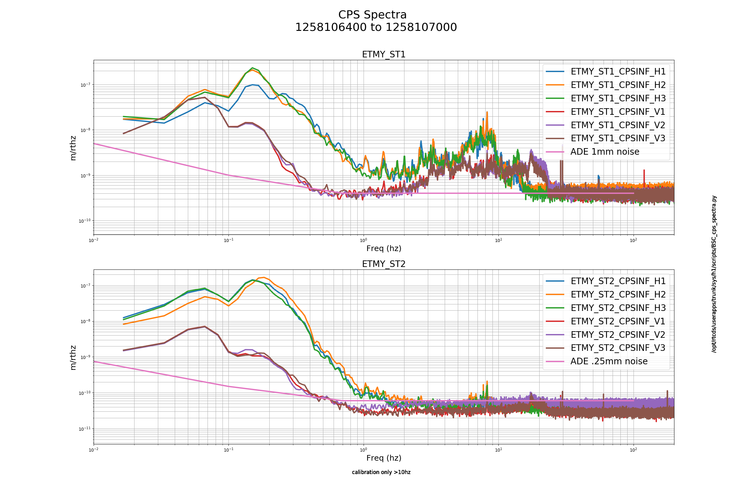
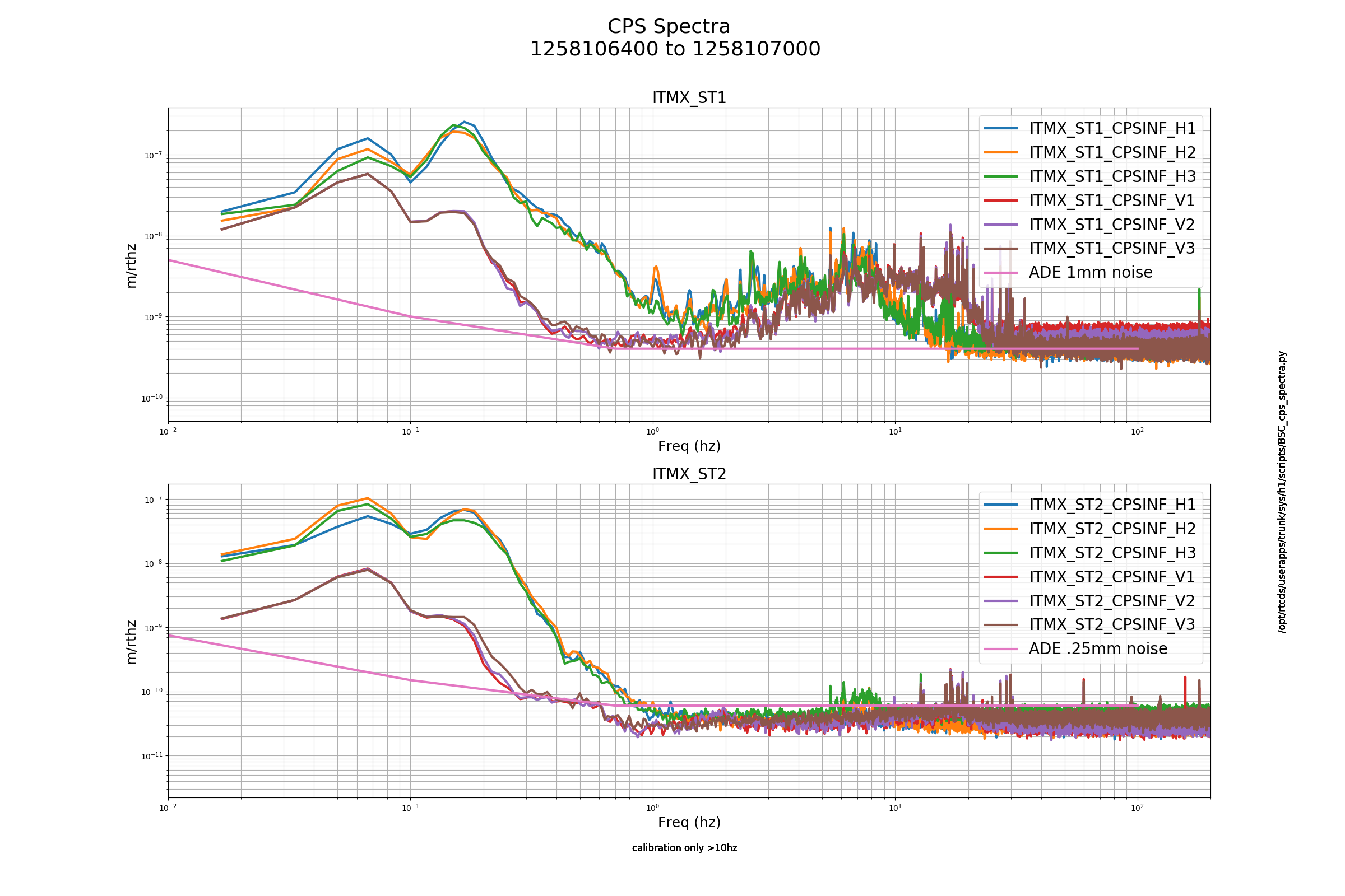
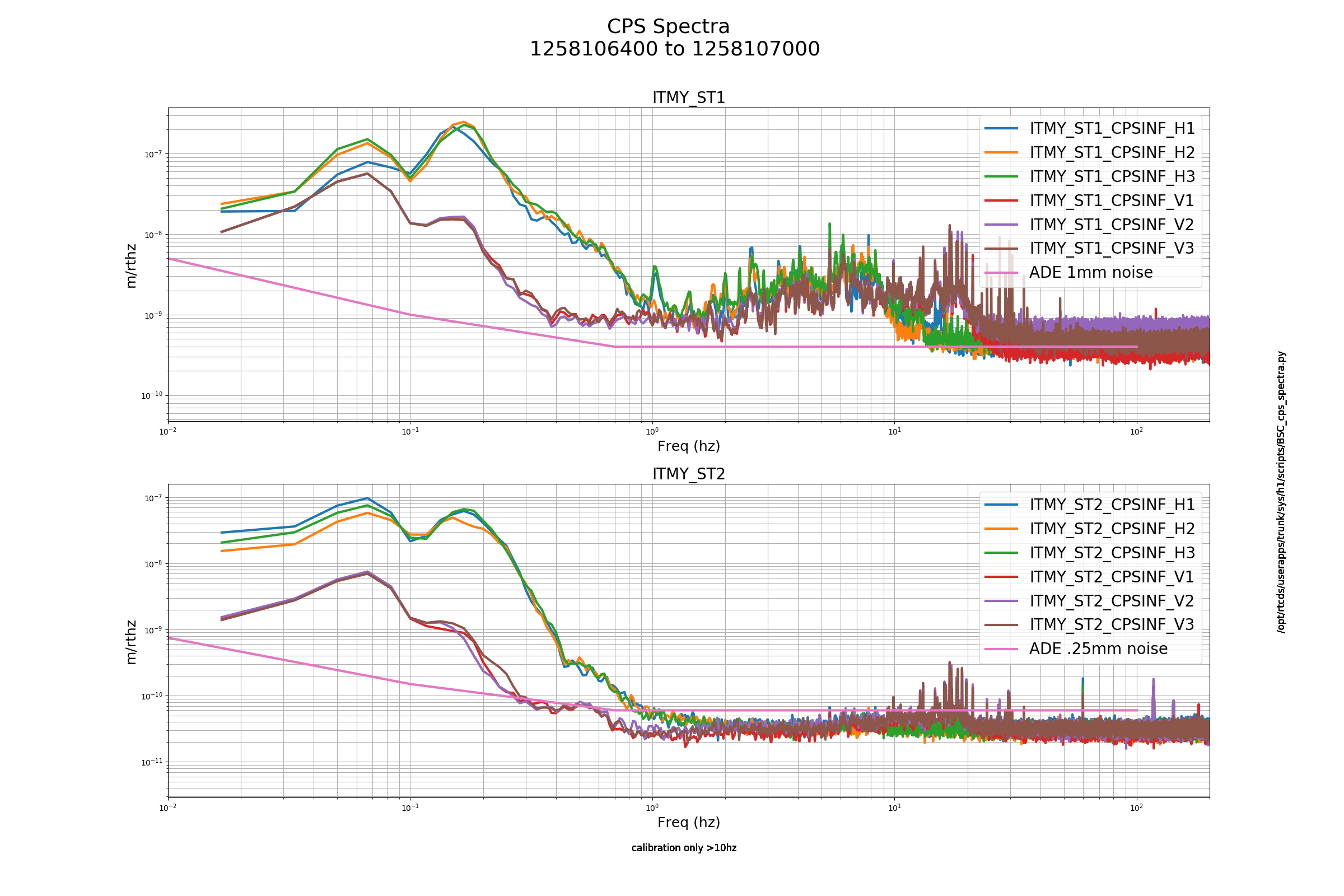
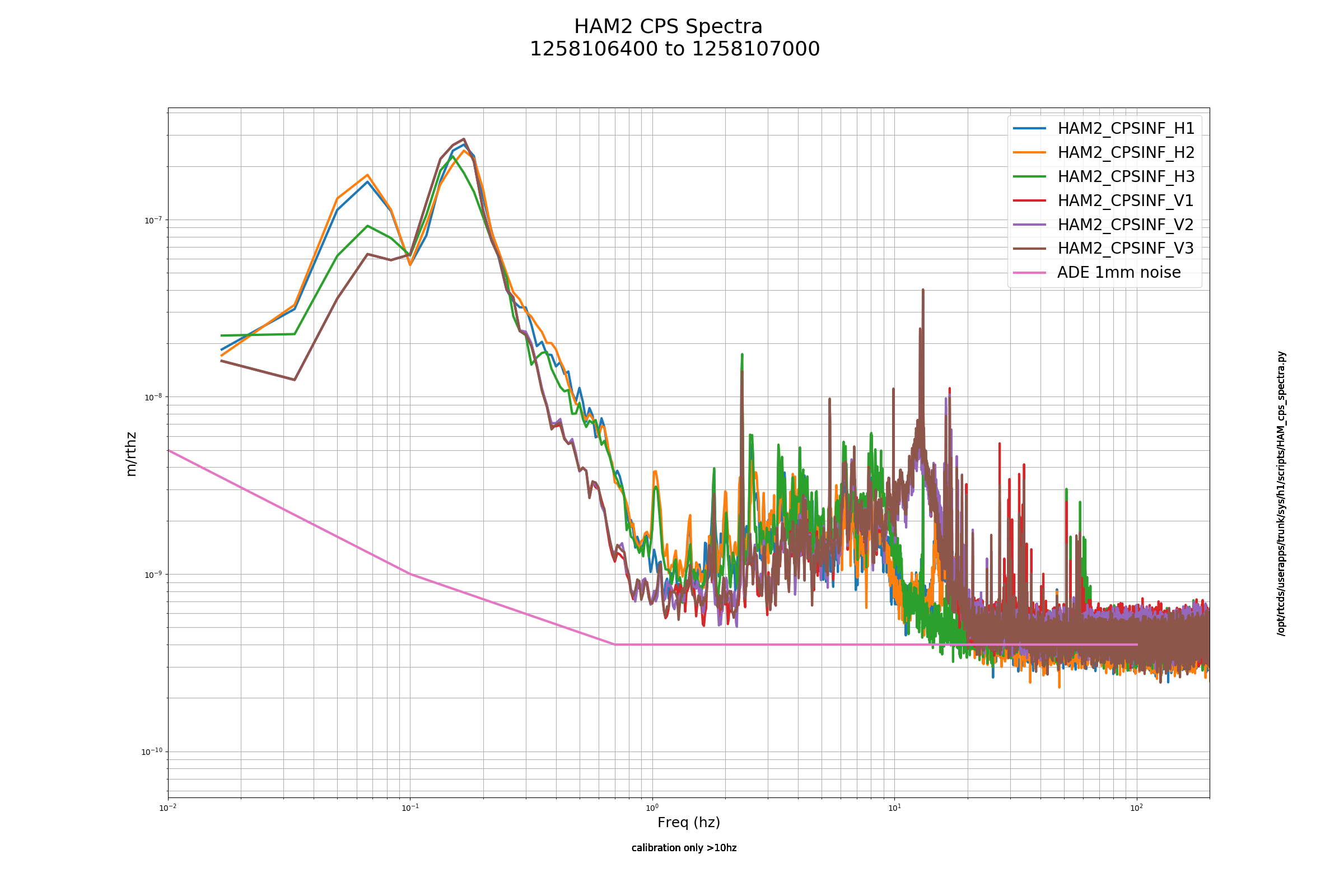
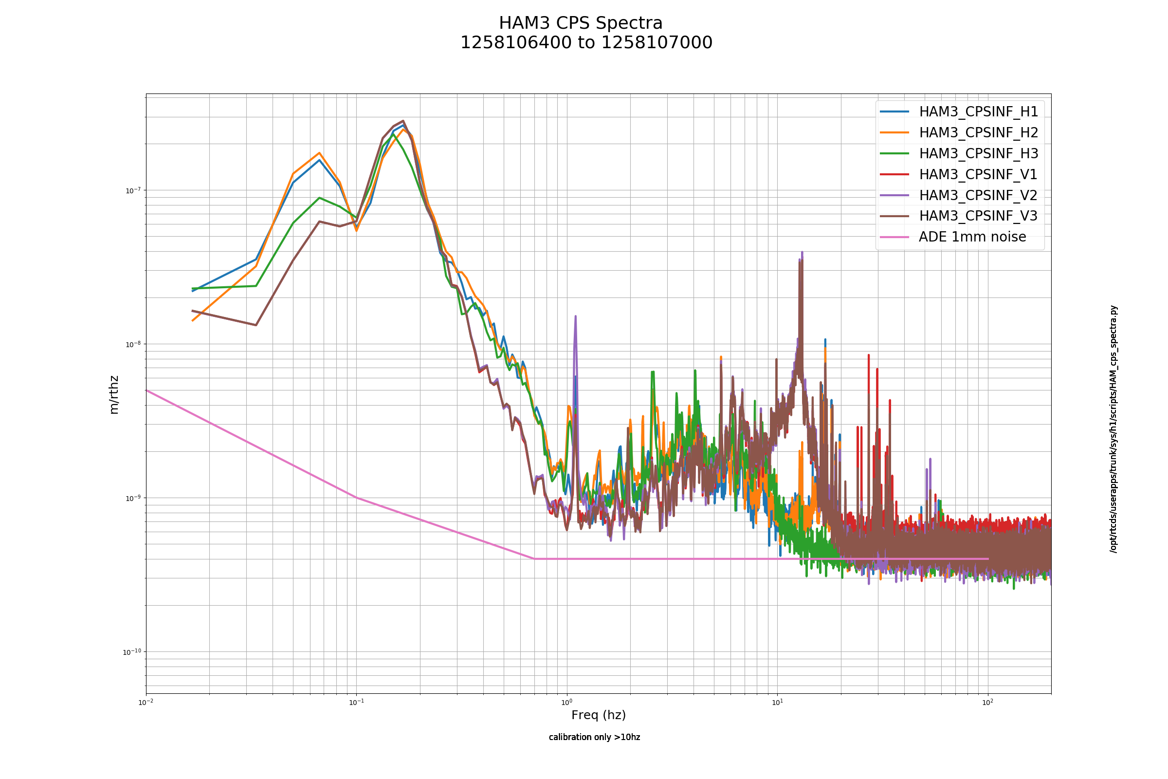
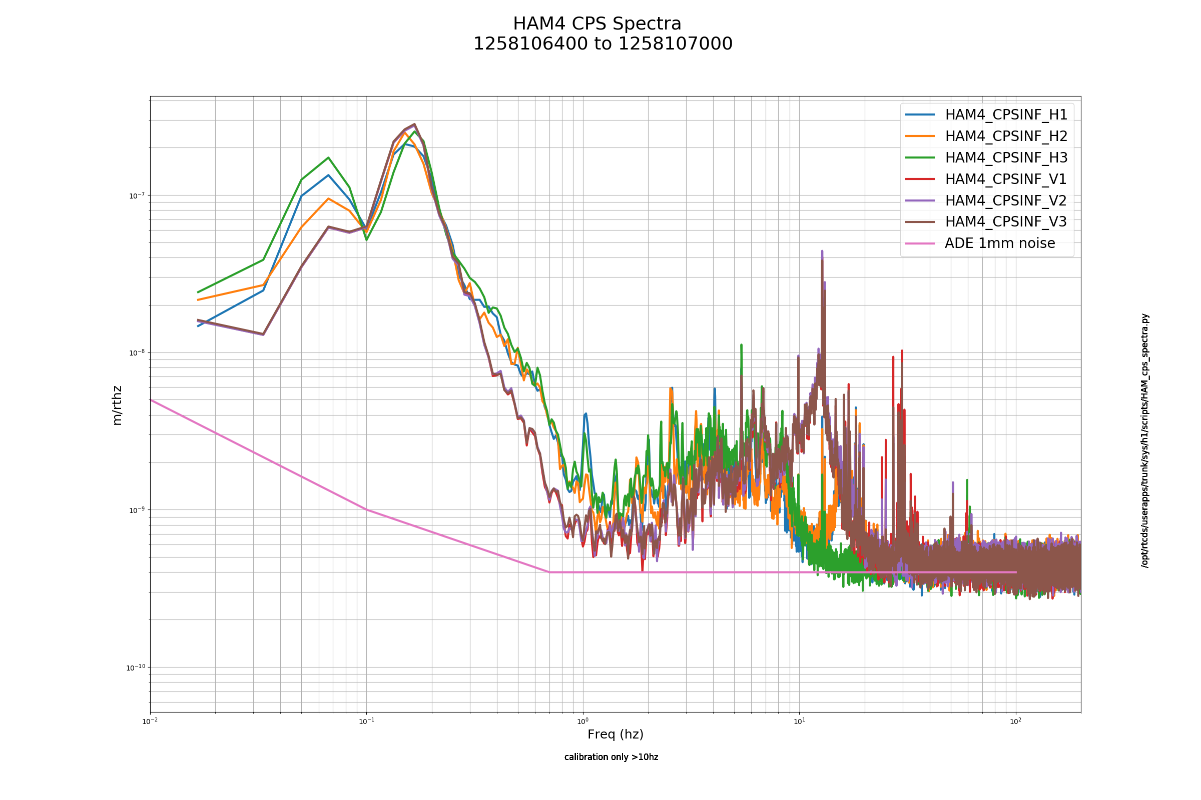
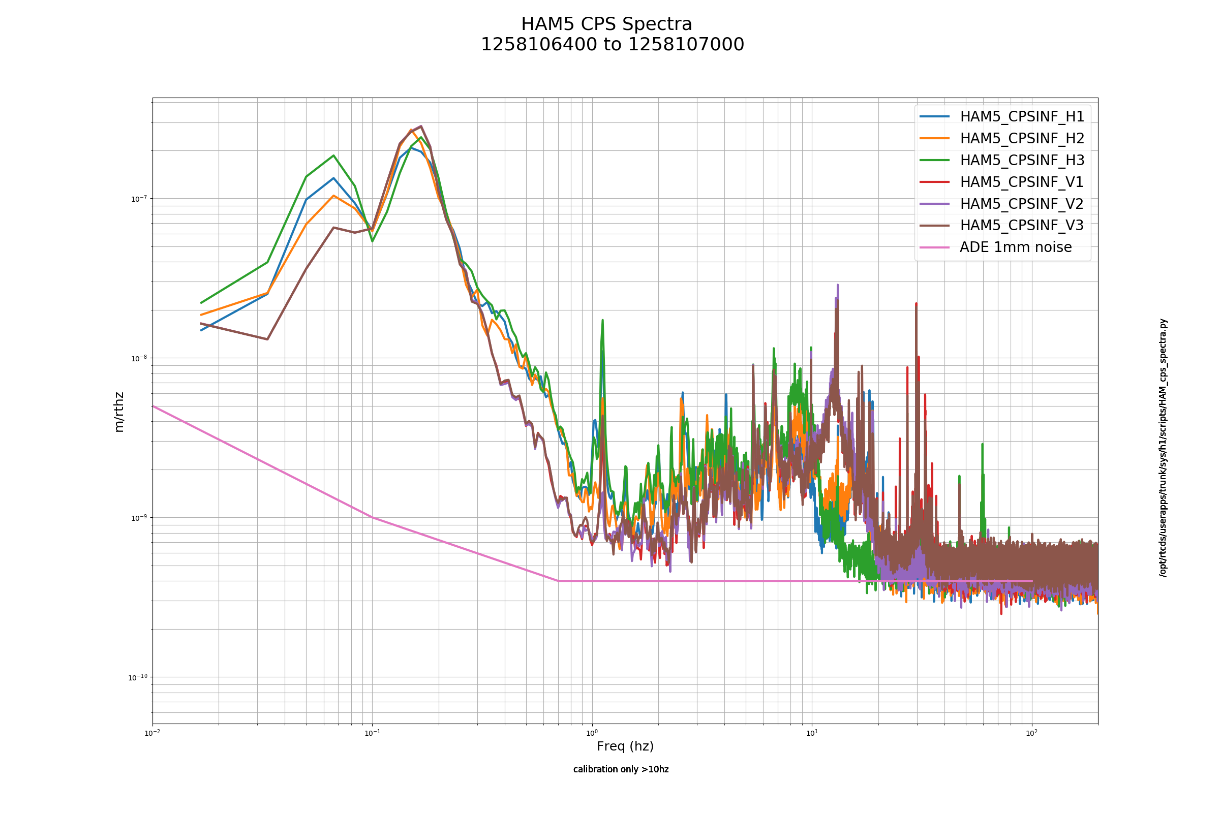
HAM CPS and BSC CPS spectra: FAMIS 12873
[Fil Clara, Timesh Mistry]
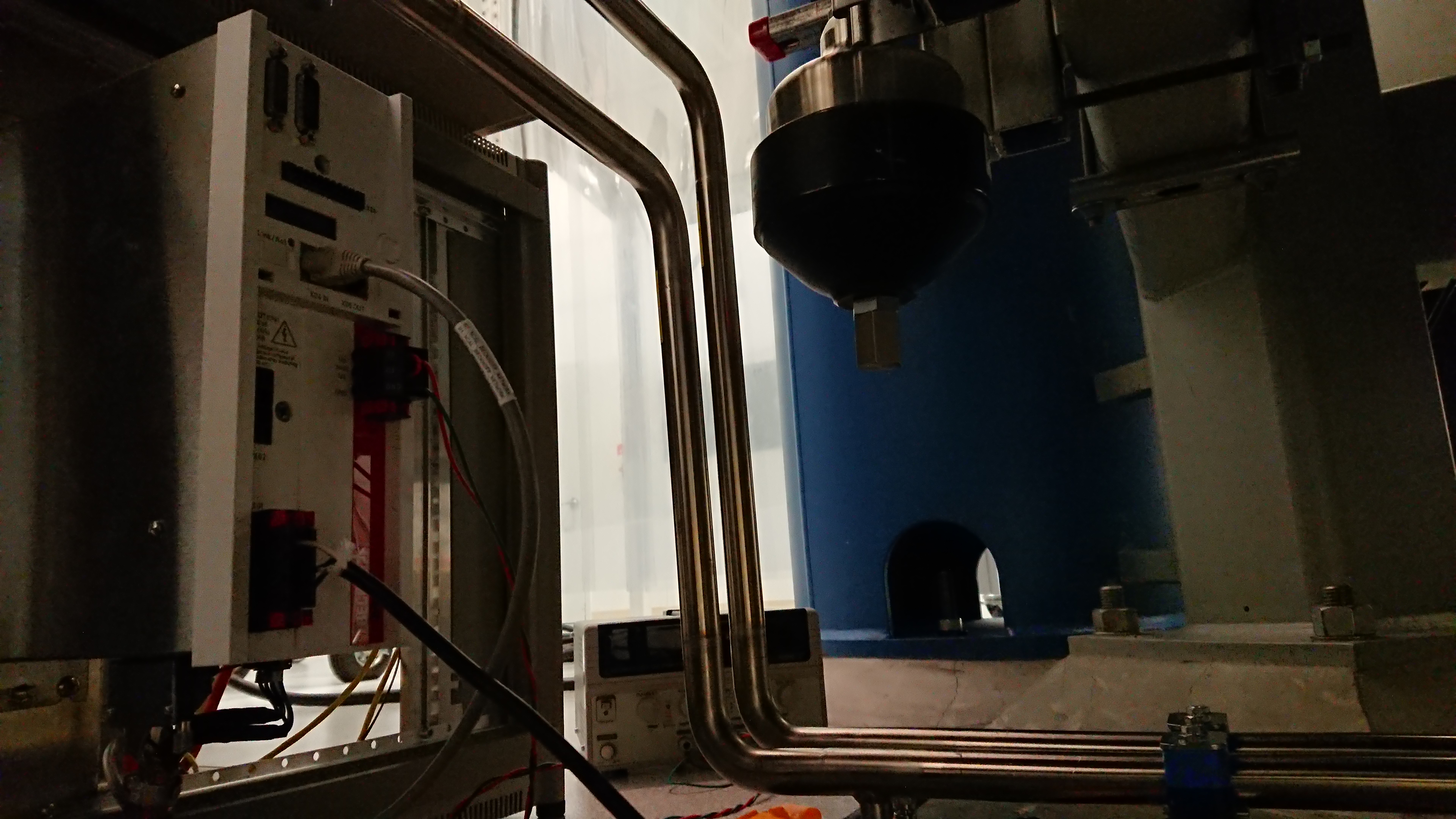
During the Earthquake, we went to the X end to unplug the ACDC power to the Beckhoff Motor Controller. This was to understand if the electronics we installed were causing any glitches in DARM (since Detchar has been noticing some glitches at the X end that coincide with the NCAL installation). With a flick of the switch, the DC power supply was turned off then we unplugged the power at around 0930 LHO time (1730 UTC) and will leave it unplugged until the next Tuesday maintenance period.
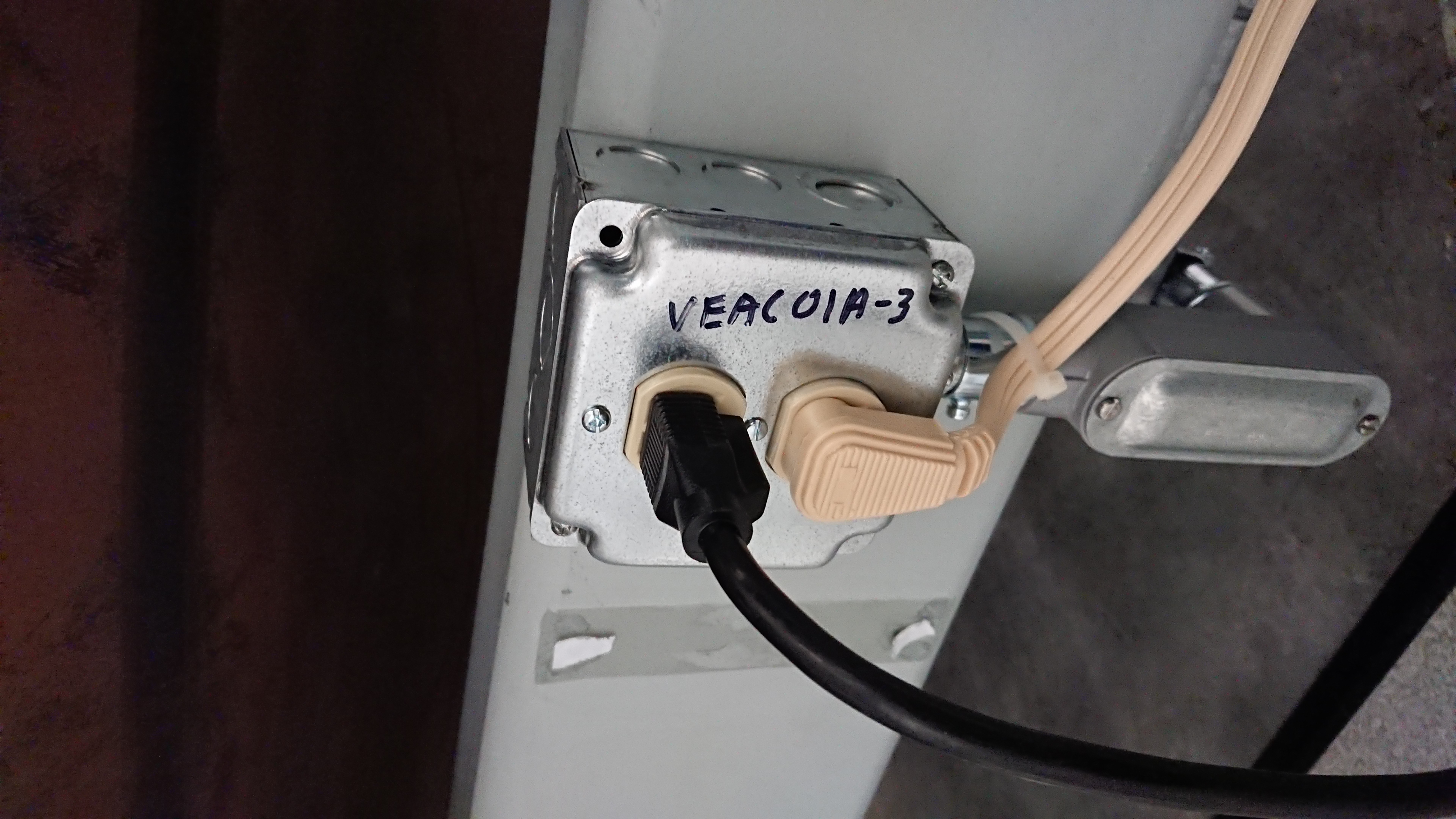
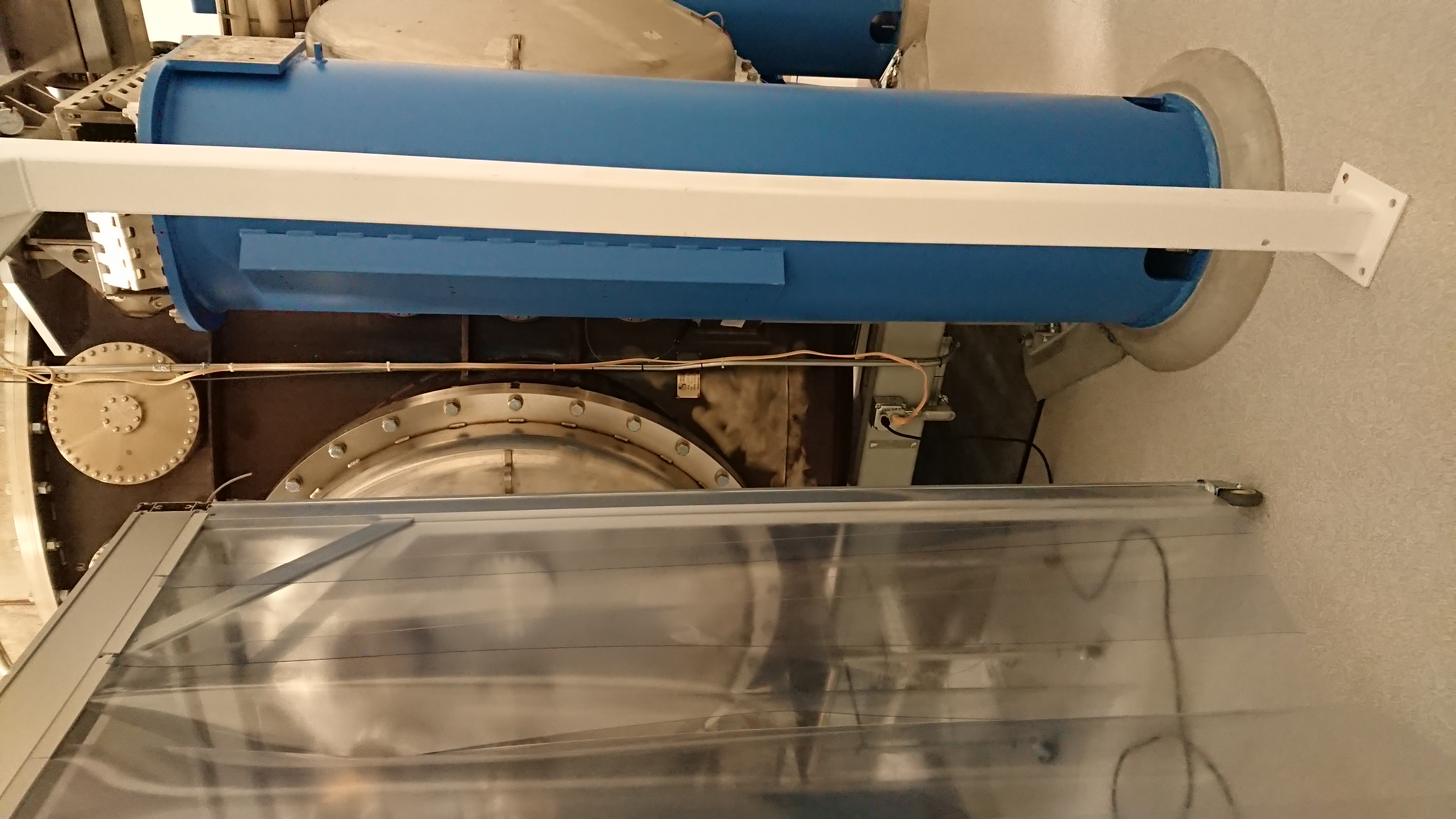
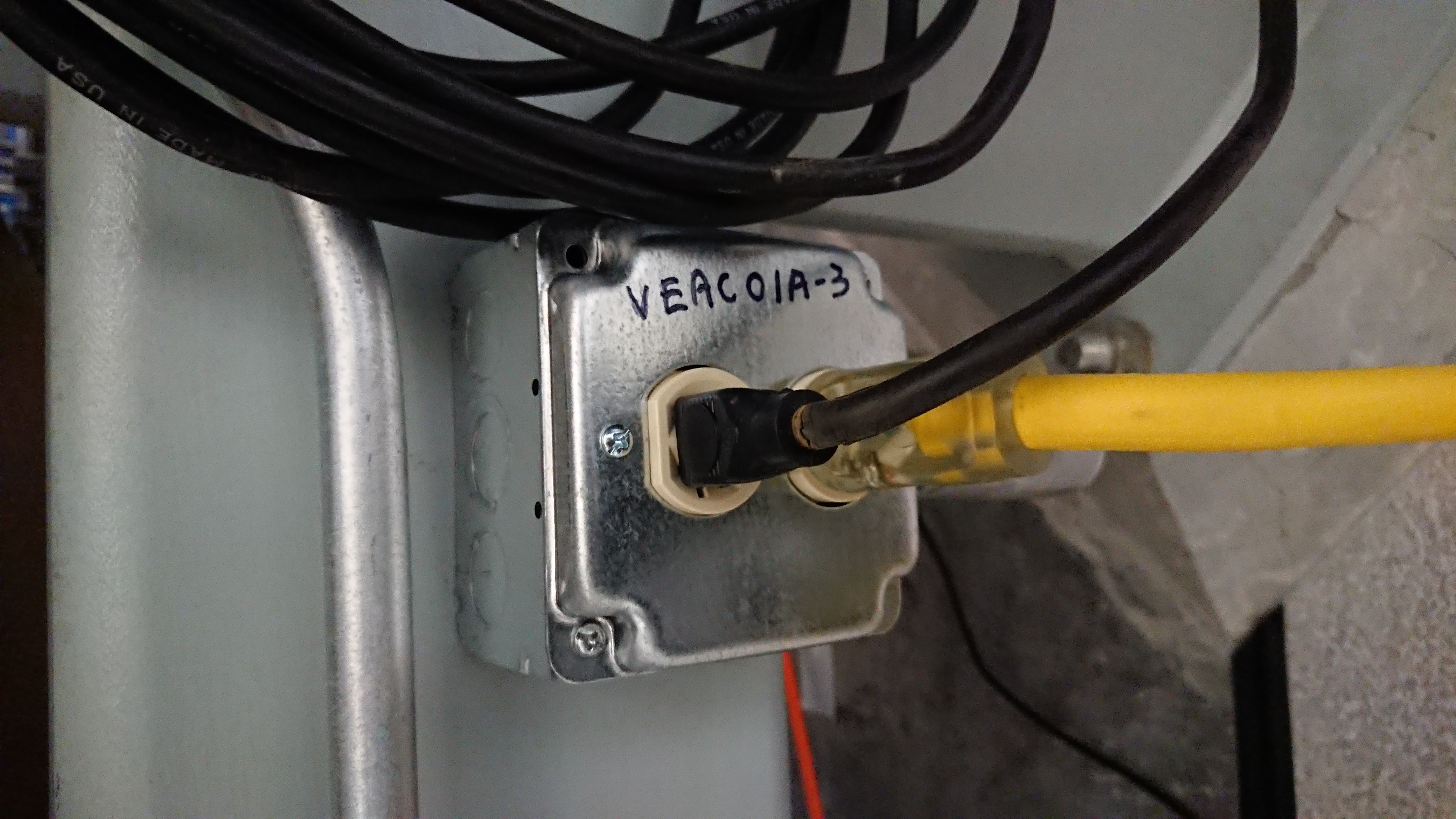
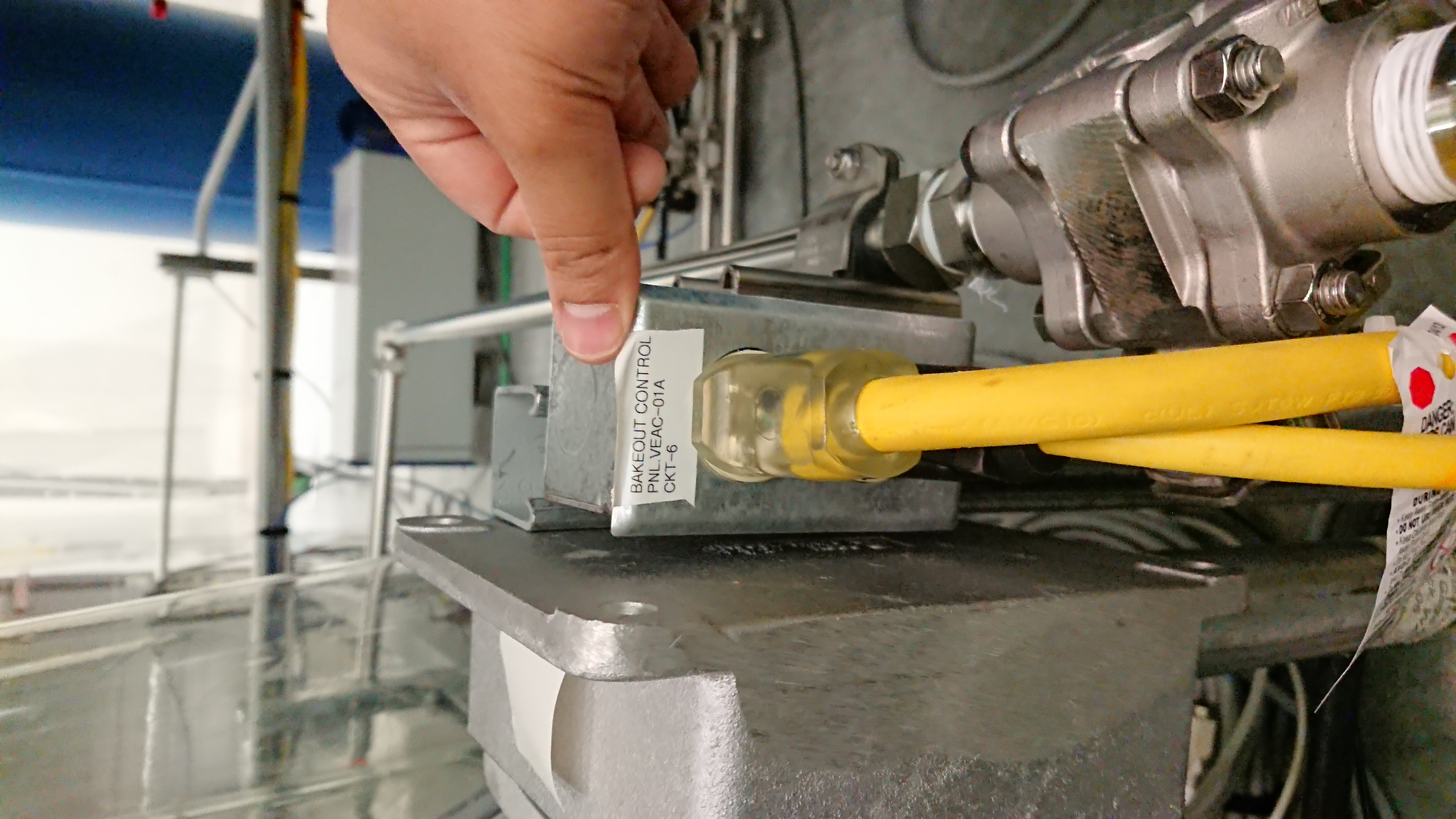
Furthermore, we took the opportunity to look for better option for plugging in the power and running the power cables. We found three possible socket locations to plug the power into:
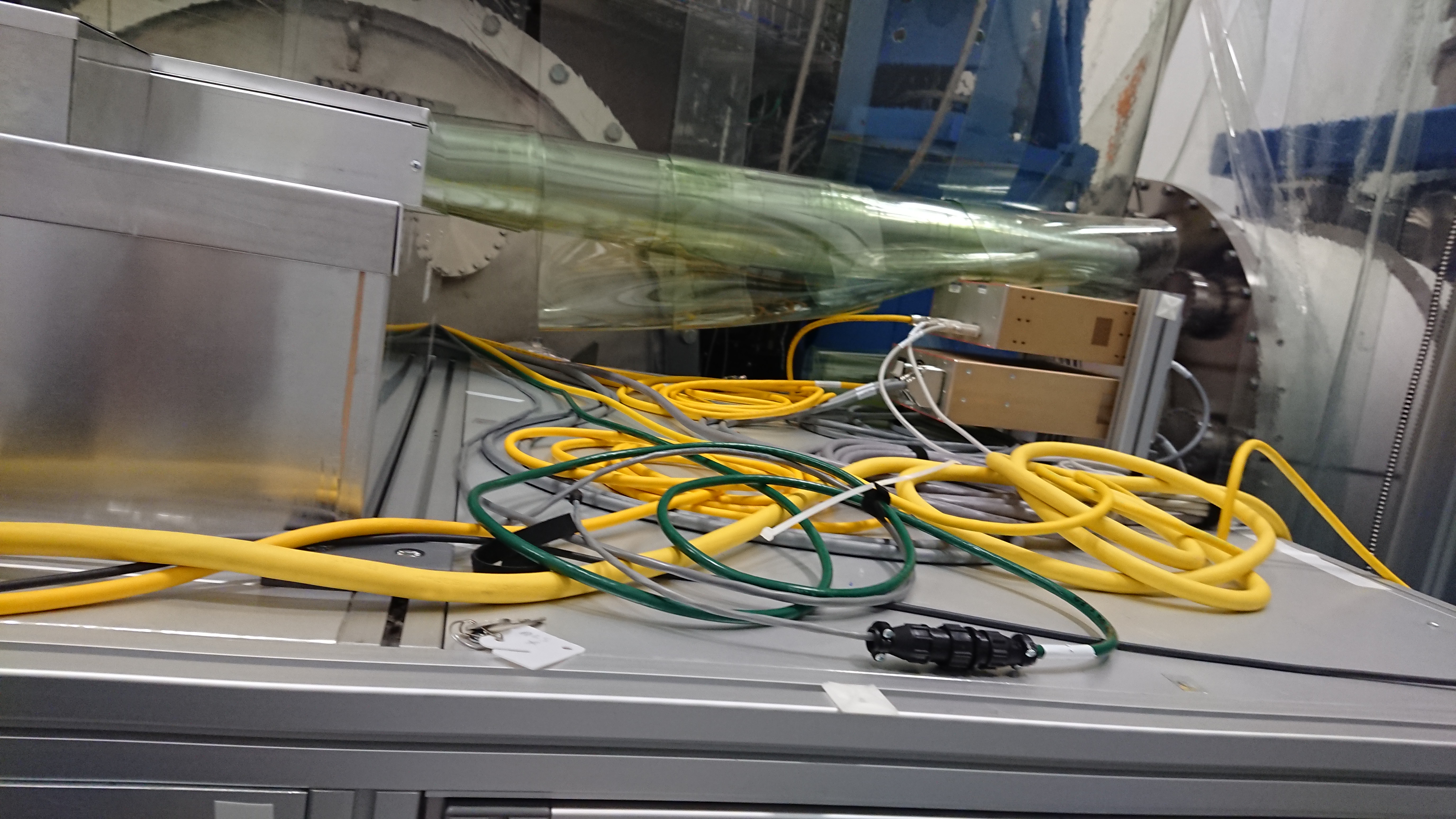
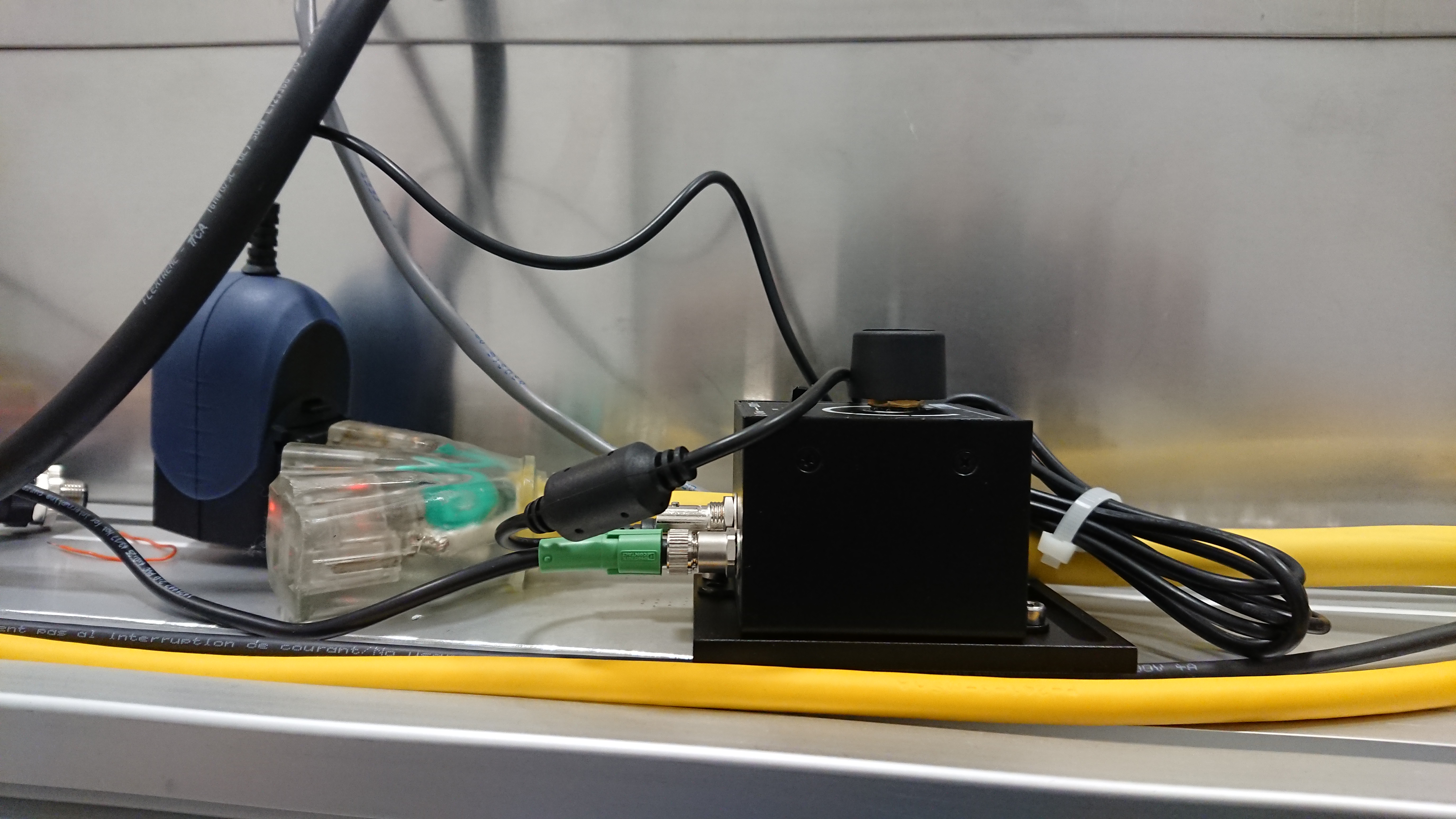
The first is located on the support structure for BSC5 as seen by the zoomed in image of the socket and the relative location can be seen in the zoomed out image. The black cable seen in the image is connected to a power strip however, there is nothing connected to the power strip so we could replace the black cable with the NCAL Beckhoff Motor Controller power.
The second location is a socket located on BSC9 as seen in the zoomed in figure. The lower yellow cable runs to the top of the HWS table however there is nothing plugged into it. There was a black box that used to be powered by this power cable but is currently disconnected. Therefore, it may be possible to disconnect the yellow power cable and power the NCAL Motor Controller from this socket. This is the most favourable location because it is the closest socket to the motor controller box/chassis.
The third location is a sockets that rises up from the floor. The zoomed image shows the name of the socket and the zoomed out image gives it relative location to the -X-Y HEPI pier and the HWS table. It is not clear if both sockets are required so we will need to check with the HWS team if it is possible to use one of these sockets.
We will confirm with the vacuum and HWS teams which socket location is the most suitable.
Would you be able to provide a list of times that the Beckhoff was powered and connected and when it was not? I'd would like to figure out if the connection has impacated spectral artifacts in addition to any glitches. Thanks in advance!
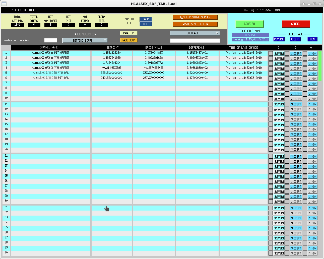
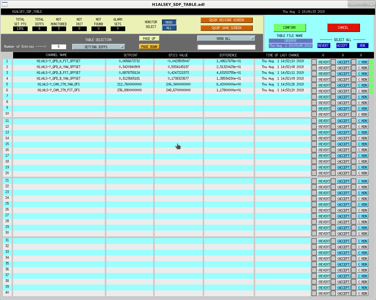
Back to NLN, Jenne and Jeff have updated ALS references, SDF diffs in attached screenshots.
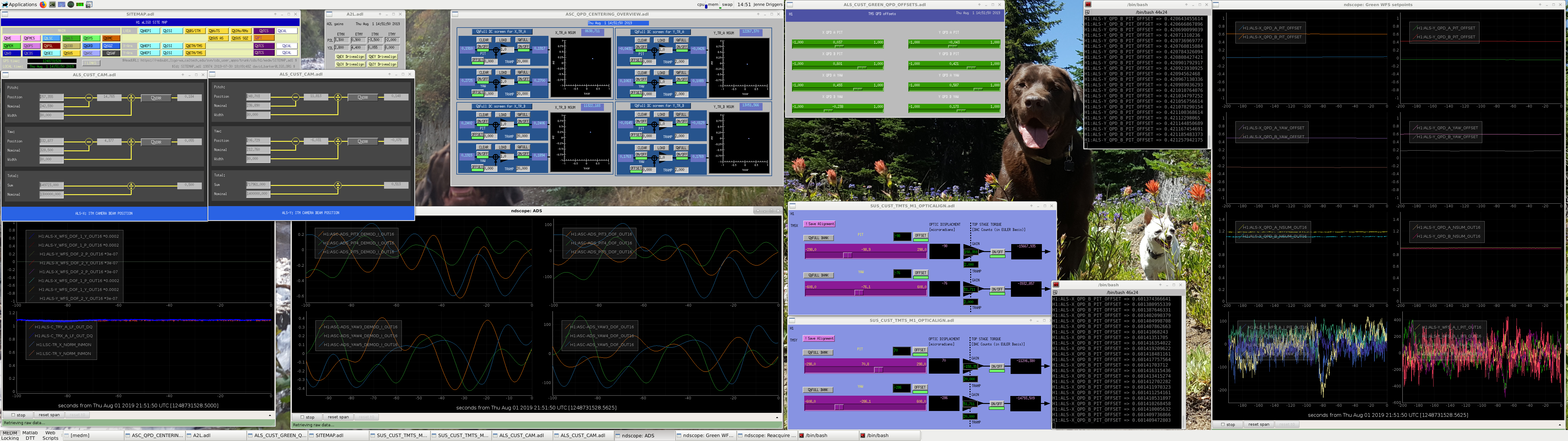
JeffK noted that we don't have a good all in one place how-to on setting the initial alignment offsets. So, here's an attempt at it. This assumes that the QPDs are all close enough to center (or can be made to be so by moving TMS) that you do not need to use the picomotors. Using the picos requires more thought and care.
The attachment is my desktop when I'm doing this, so you can see all of the windows that I'm looking at.
Process for each arm (can be done in parallel since each arm is independant of the other for this work):
If you must pico, I'd recommend only pico-ing the IR QPDs since they're much easier to think about and independent of other beams. I'd start the green QPD setpoint scripts to make the green QPDs follow your movement. Then I'd make a small step in TMS alignment in the direction that will put the green QPD offsets closer to zero, and then pico the IR steering picos to get the IR QPDs closer to zero.
I've edited the code that sets the green QPD offsets (/opt/rtcds/userapps/trunk/als/h1/scripts/setEndGreenQPDOffsets_XARM.py and setEndGreenQPDOffsets_YARM.py) -- check out LHO aLOG 51476 for further commentary.
This procedure needs to be modified because we are now setting green references with our spots centered on the optics. We would like to center the IR on the IR QPDs once we have our spots in their final positions, however, not necessarily with the spots centered.
Since Craig added in the TMS servoing to center the IR QPD, we should still be able to follow this procedure at DC readout. At DC readout, in the current situation, we are servoing the spots to the centers of all 4 test masses at 2W input power. This is the position we want to set the initial alignment references to.
Later in the acquisition sequence the power is increased to 10W, and then the beam spots are moved to their final high power positions, then we further increase the power and continue on to NomLowNoise.
Before setting the green camera references, we should remember to check that the camera image is good and that any mask applied is appropriate. We can check this by opening up the digital camera screen and taking a snapshot, then finding the snapshot in /ligo/data/camera