Displaying reports 37681-37700 of 89095.Go to page Start 1881 1882 1883 1884 1885 1886 1887 1888 1889 End
Reports until 09:57, Tuesday 05 November 2019
H1 ISC
stefan.ballmer@LIGO.ORG - posted 09:57, Tuesday 05 November 2019 - last comment - 09:57, Tuesday 05 November 2019(52979)
Spectrogram before and after range drop

We have been chasing the reason for th3e range drops all day today. Here is another negative:

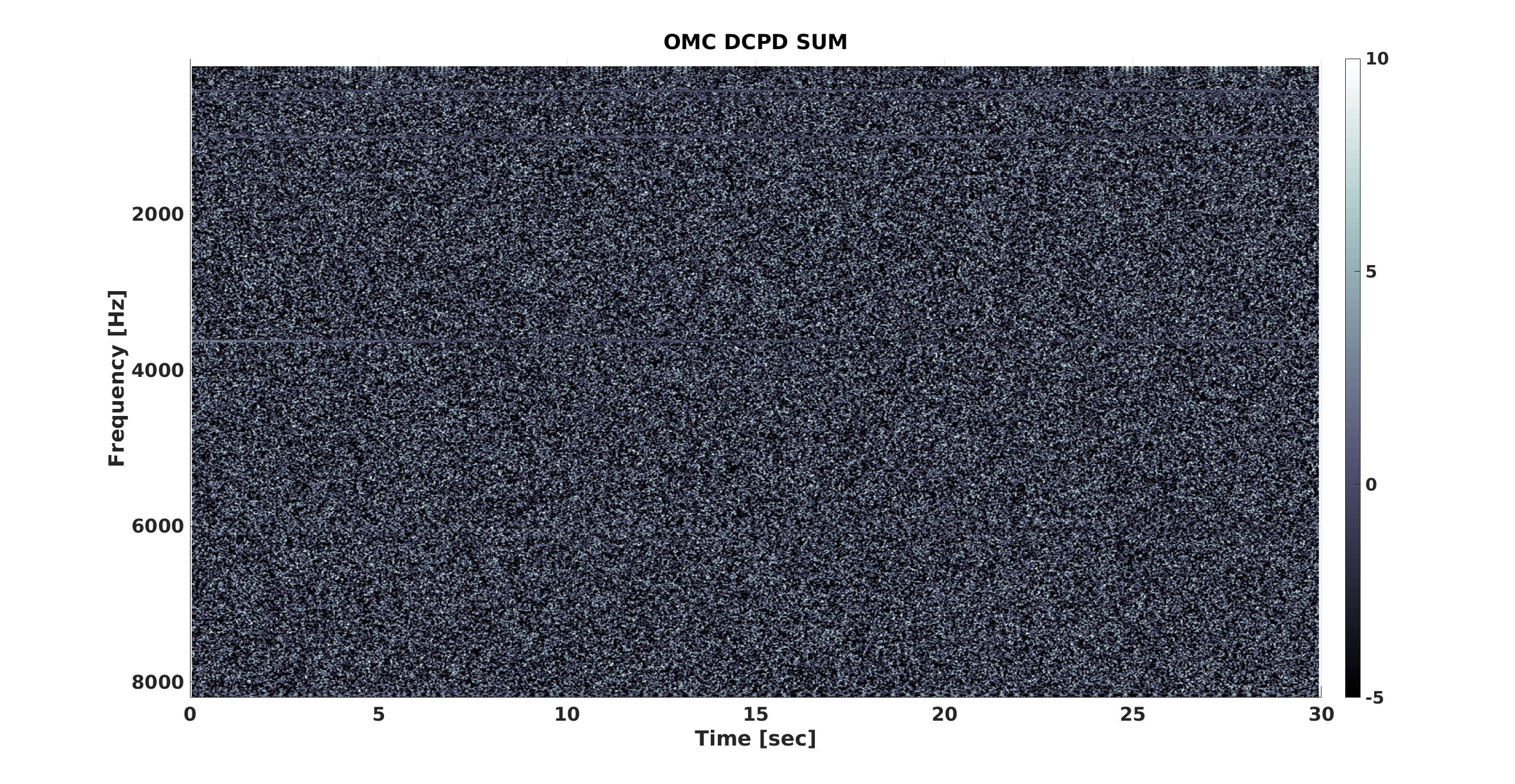
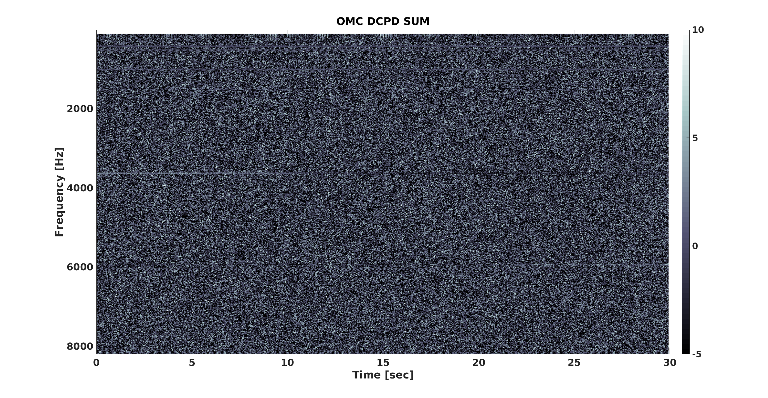
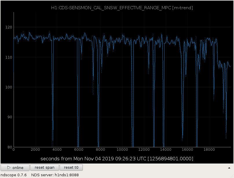
Suspecting something like "microwhistles" I made a 30sec spectrogram before and after the range drop. I don't see any difference in the statistics.

Good: GPS 1256894801
Bad:   GPS 1256914735

Plot 1: Range, the date in the spectrogram corresponds to the first 30seconds (good) and the last 30 seconds (bad).
Plot 2: Spectrogram of the good time.
Plot 3: Spectrogram of the bad time.


==============

Plot 4 and plot 5 show spectrogram centered around the range drop at GPS 1256913467. (plot 4 GPS start 1256913437, plot 5 GPS start 1256913452,)
Note the slight increase in the noise level, but no associated pattern whatsoever. The range indeed dropped within 1 second.
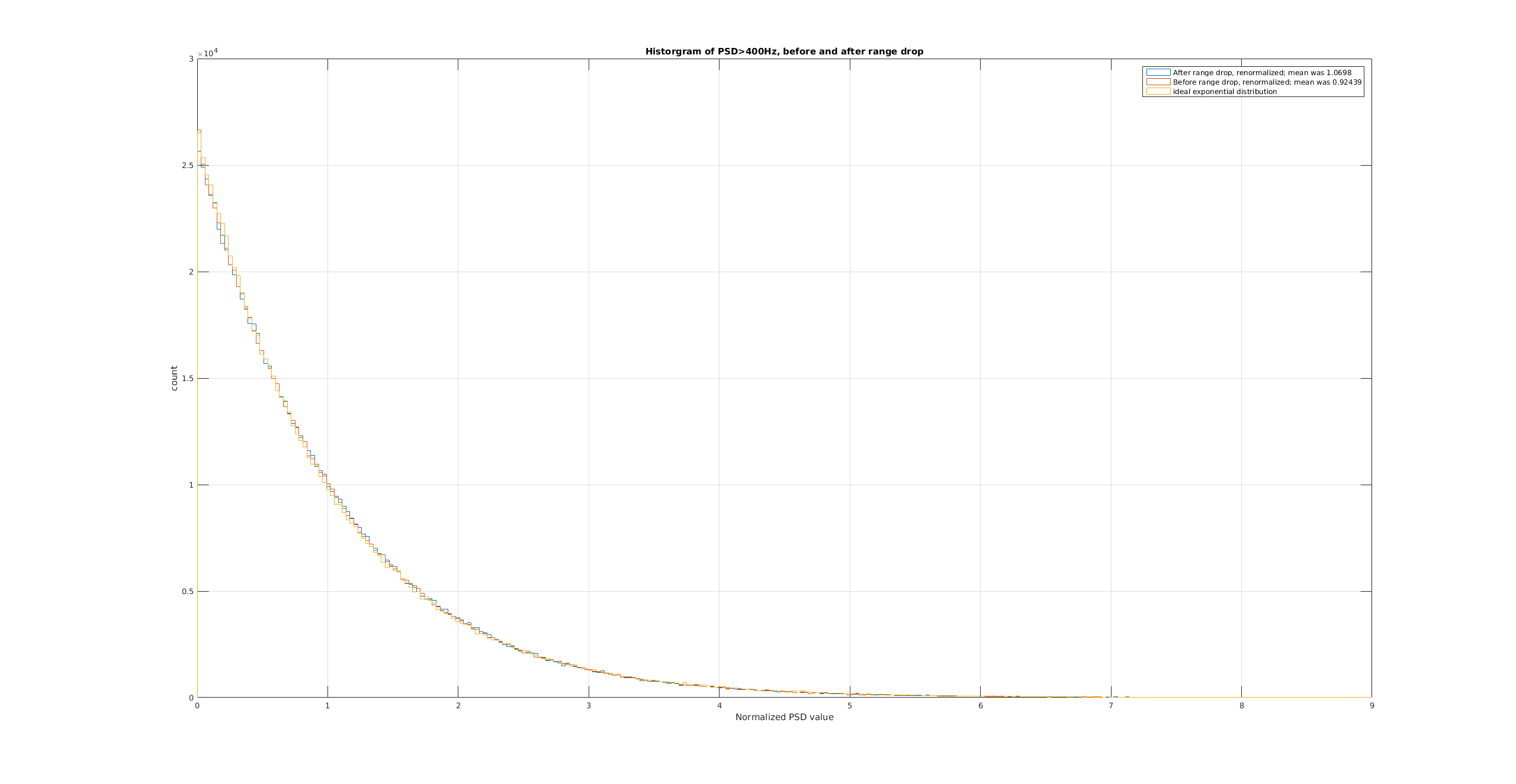
Finally, plot 6 shows histograms of the PSD values before and after the range drop, renormalizing with the mean. Both histograms are indistingushable from an exponmential distribution.

Images attached to this report
Comments related to this report
stefan.ballmer@LIGO.ORG - 16:33, Monday 04 November 2019 (52980)

Daniel, Stefan

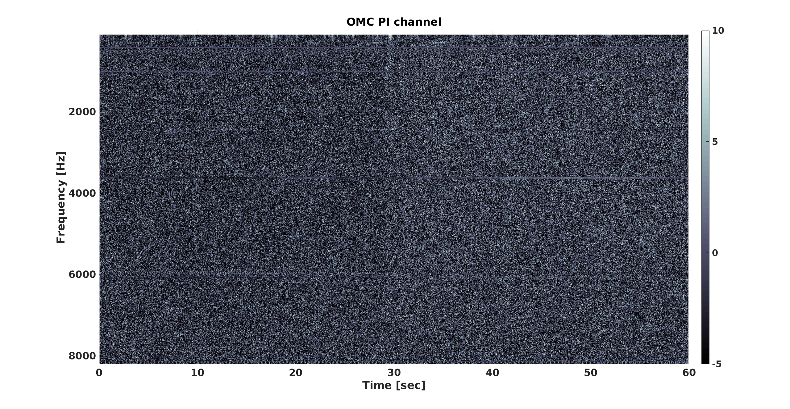
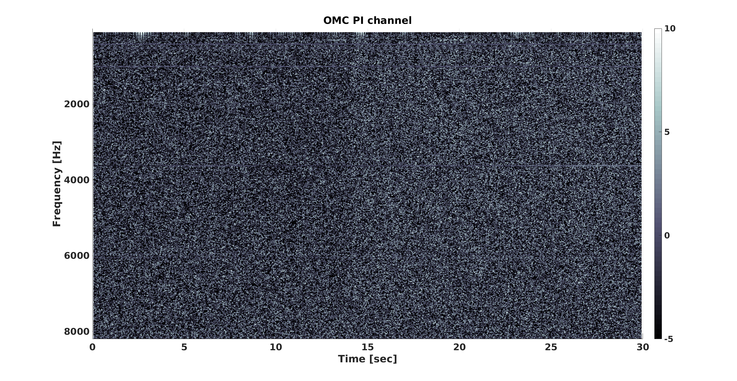
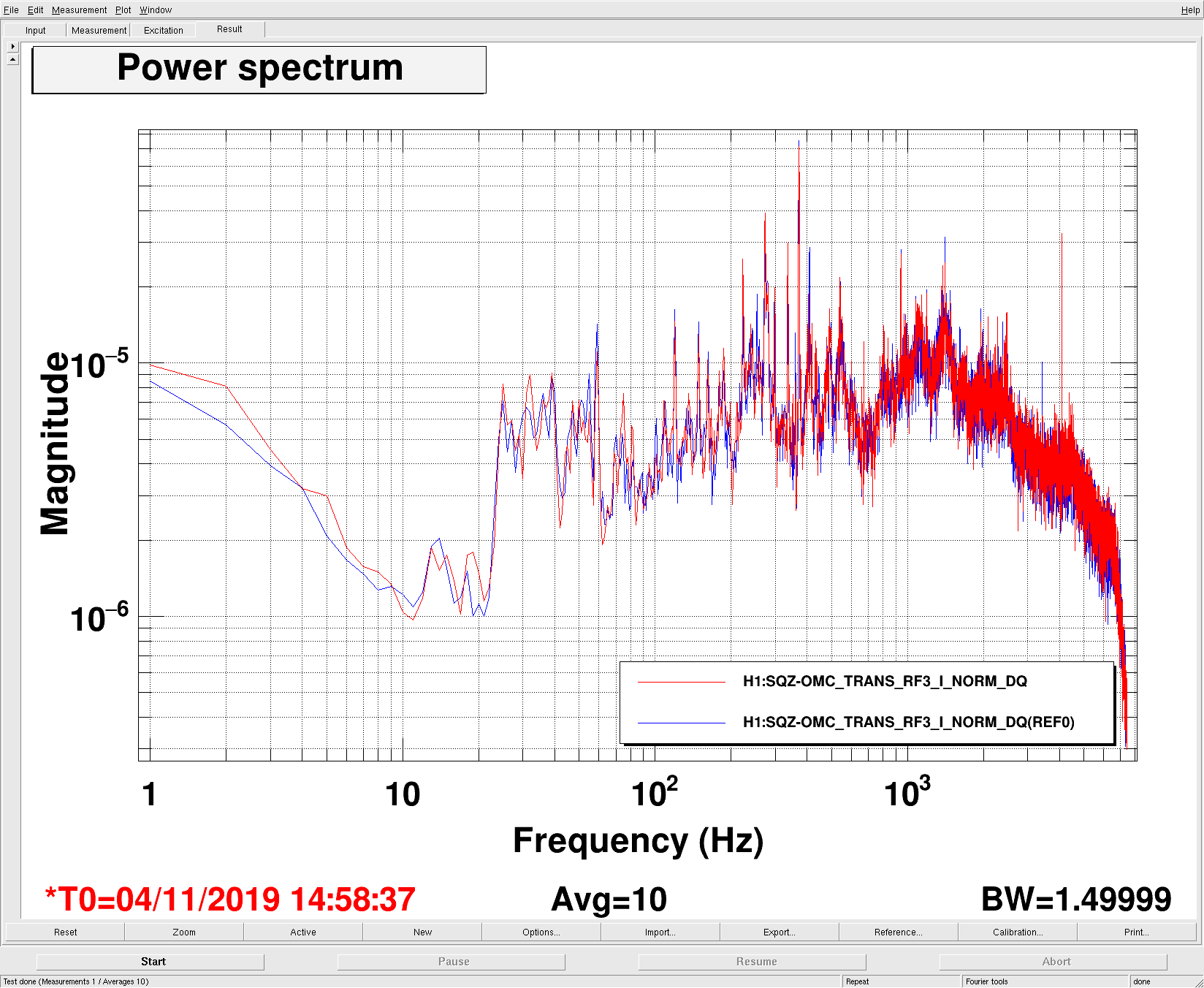
Suspecting some excess phase noise in the squeezer phase locking loop, we bade spectra of the error point for the same good and bad times.

They look the same. Yet another null result...

(That technically does not rule out excess phased noise above the Nyquist frequency.)


Images attached to this comment
H1 General
jim.warner@LIGO.ORG - posted 00:00, Tuesday 05 November 2019 (52990)
Shift Summary

TITLE: 11/05 Eve Shift: 00:00-08:00 UTC (16:00-00:00 PST), all times posted in UTC
STATE of H1: Observing at 111Mpc
INCOMING OPERATOR: Jeff
SHIFT SUMMARY: Lots of GRBs
LOG:
0:00 Ifo lost lock due to an eq before I arrived, waited for 20 minutes and struggled with PRMI/DRMI while the eq took it's time to ring down

0:25 Initial alignment

1:53 NLN and observing

6:29 SQZ relocks, knocking us out of observing


H1 TCS (DetChar)
daniel.brown@LIGO.ORG - posted 23:55, Monday 04 November 2019 - last comment - 01:49, Tuesday 05 November 2019(52989)
Phase camera overheating, powerup + CO2X test round 2

In the movie linked in alog 52927 we saw the phase camera begining to fail in a way we hadn't seen before, around 35s into the movie. We ran it again during throughout the lock acquisition today and it lasted much longer into the lock however it started to happen again. It seems the resonant circuit used to drive the pockel cell has reached some temperature limit after prolonged use. When we reduce the driving voltage by half we start seeing the same images as we did before, except with 50% reduction in amplitude. Leaving it to cool down also seems to fix the problem for the first few images but the it starts up quickly again. Something to be fixed in the next version.

We also wanted to try the CO2X test again (agreed with Keita) where we drop CO2X and then raise it up again to see how the carrier+sideband mode matching changes. The change will be small +-100mW left over an hour. Short jumps out and back into observing will be required, I'll comment GPS times when we start.

However we just had yet another GRB event so we're standing down again, hopefully can try this later.

Comments related to this report
daniel.brown@LIGO.ORG - 00:24, Tuesday 05 November 2019 (52992)DetChar

Starting: 1256977145

Seems the CO2 powers aren't actually tracked by the SDF, so I won't drop out of observe next time.

daniel.brown@LIGO.ORG - 01:49, Tuesday 05 November 2019 (52995)

Finished up at 1256982152. Went back to nominal CO2X setting as DHARD P 0.6Hz started to get angry.

H1 SQZ (SQZ)
nutsinee.kijbunchoo@LIGO.ORG - posted 21:54, Monday 04 November 2019 (52988)
Several SQZ/ASQZ measurements with the homodyne. *Maybe* keep an eye on the crystal degradation

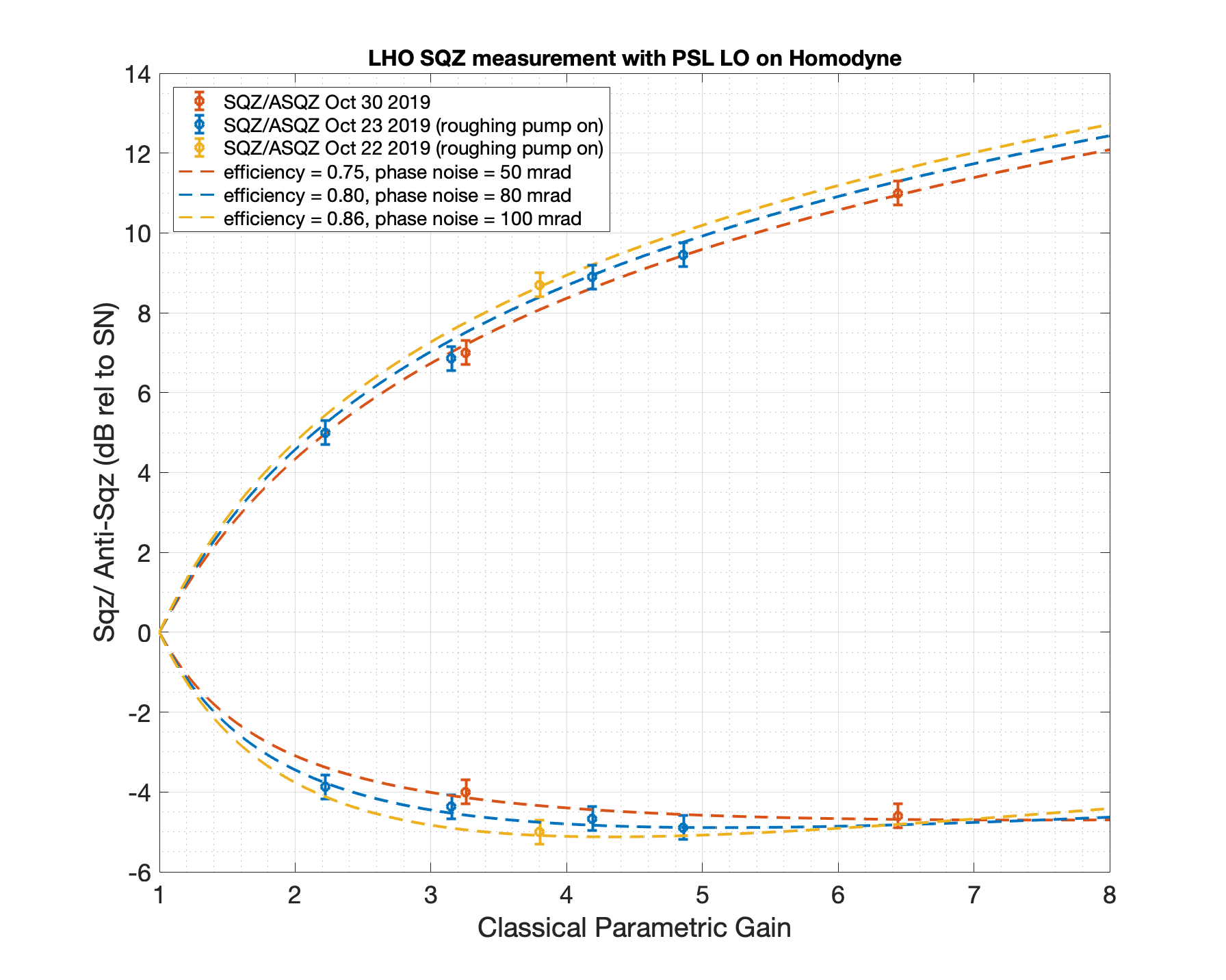
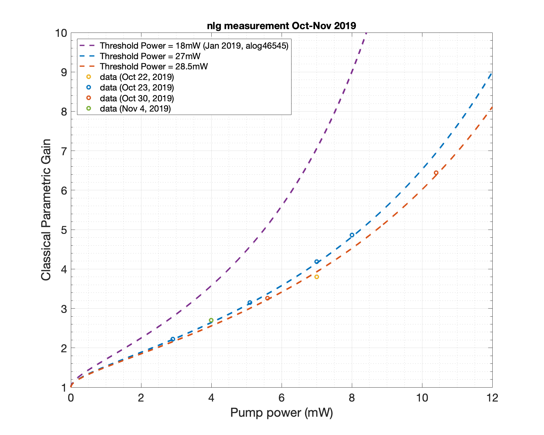
Here I compiled several days worth of sqz/asqz measurements with the homodyne in one plot. Everytime I make a measurement I get slightly more and more loss infer from antisqueeze. This could be an indication that our crystal is slowly degrading. However, it is also possible that I have a large uncertainty in the nonlinear gain measurement so it's difficult to draw a solid conclusion from the data taken during the past few days. It is true though that we used to have a threshold power of 18mW. Something to keep an eye out for.


Images attached to this report
H1 CAL (CAL)
timesh.mistry@LIGO.ORG - posted 18:38, Monday 04 November 2019 - last comment - 19:04, Monday 04 November 2019(52986)
NCAL Update -- Channels in the Front End

[Dave B, Timesh M]

While the IFO was recovering from an earthquake, we took the opportunity to go to the X end and connect the NCAL Beckhoff PC to the network. We are now able to ping the PC, read and write to all the Beckhoff channels. Using the epics caget routine, we confirmed that we can read the data from the channels. We have not tried writing to the channels using caget. It is not possible to accidently spin the NCAL since the NCAL comms cable had not been connected from the motor controller to the motor. In addition, we were unable to set up the remote desktop to the NCAL PC since, we were unable to add controls as a remote user to the NCAL PC. It is currently not possible to search the channels using chndump since a DAQ restart would be required to add the new channels names to the channel list.

The new Beckhoff channels are:

H1:CAL-NCALX_POWER_ENABLE*
H1:CAL-NCALX_MOVE_VELOCITY_VELOCITY_REQ*
H1:CAL-NCALX_MOVE_VELOCITY_EXECUTE*
H1:CAL-NCALX_HALT_EXECUTE*
H1:CAL-NCALX_RESET_EXECUTE*
H1:CAL-NCALX_TRIP_RESET*
H1:CAL-NCALX_AXIS_ERROR
H1:CAL-NCALX_AXIS_ERROR_ID
H1:CAL-NCALX_SOE_READ_BUSY
H1:CAL-NCALX_SOE_READ_ERROR
H1:CAL-NCALX_SOE_READ_ADS_ERR_ID
H1:CAL-NCALX_SOE_READ_SERCOS_ERR_ID
H1:CAL-NCALX_POWER_STATUS
H1:CAL-NCALX_POWER_ERROR
H1:CAL-NCALX_POWER_ERROR_ID
H1:CAL-NCALX_MOVE_VELOCITY_BUSY
H1:CAL-NCALX_MOVE_VELOCITY_ERROR
H1:CAL-NCALX_MOVE_VELOCITY_ERROR_ID
H1:CAL-NCALX_HALT_BUSY
H1:CAL-NCALX_HALT_ERROR
H1:CAL-NCALX_HALT_ERROR_ID
H1:CAL-NCALX_RESET_BUSY
H1:CAL-NCALX_RESET_ERROR
H1:CAL-NCALX_RESET_ERROR_ID
H1:CAL-NCALX_TRIP_HALT_BUSY
H1:CAL-NCALX_TRIP_HALT_ERROR
H1:CAL-NCALX_TRIP_HALT_ERROR_ID
H1:CAL-NCALX_TRIP_LATCH
H1:CAL-NCALX_TRIP
H1:CAL-NCALX_VELOCITY
H1:CAL-NCALX_TORQUE
H1:CAL-NCALX_CURRENT

* = Read and write channels

The NCAL wiki will have more information with regards to the channel names. The MEDM screen is being populated with the relevant channel names.

To Do:

- Correctly route the cables in the racks.
- Add controls as a remote user to the NCAL PC.
- Connect the optical encoder to the rack.
- Test spin using over epics.
- Test safety/emergency procedures for NCAL.
- DAQ restart to add the Beckhoff channels to the channel list.
- Spin with full IFO.
- Use current PEM sensors and evaluate noise.
- Configure front end model to track optical encoder and provide real time force estimate.


Comments related to this report
timesh.mistry@LIGO.ORG - 19:04, Monday 04 November 2019 (52987)CAL

The channels as added by the DAQ restart (LHO alog 52768) for the NCAL front end model are:

timesh.mistry@zotws22: chndump | grep H1:CAL-NCALX
H1:CAL-NCALX_ENCODER_VELOCITY_EXC   1   0     1   4  16384   0
H1:CAL-NCALX_ENCODER_VELOCITY_EXCMON   1   0     0   4     16   0
H1:CAL-NCALX_ENCODER_VELOCITY_GAIN   1   0     0   4     16   0
H1:CAL-NCALX_ENCODER_VELOCITY_IN1   1   0 10001   4  16384   0
H1:CAL-NCALX_ENCODER_VELOCITY_IN2   1   0 10002   4  16384   0
H1:CAL-NCALX_ENCODER_VELOCITY_INMON   1   0     0   4     16   0
H1:CAL-NCALX_ENCODER_VELOCITY_LIMIT   1   0     0   4     16   0
H1:CAL-NCALX_ENCODER_VELOCITY_OFFSET   1   0     0   4     16   0
H1:CAL-NCALX_ENCODER_VELOCITY_OUT   1   0 10003   4  16384   0
H1:CAL-NCALX_ENCODER_VELOCITY_OUT16   1   0     0   4     16   0
H1:CAL-NCALX_ENCODER_VELOCITY_OUT_DQ   1   0     0   4   4096   0
H1:CAL-NCALX_ENCODER_VELOCITY_OUTPUT   1   0     0   4     16   0
H1:CAL-NCALX_ENCODER_VELOCITY_SWMASK   1   0     0   4     16   0
H1:CAL-NCALX_ENCODER_VELOCITY_SWREQ   1   0     0   4     16   0
H1:CAL-NCALX_ENCODER_VELOCITY_SWSTAT   1   0     0   4     16   0
H1:CAL-NCALX_ENCODER_VELOCITY_TRAMP   1   0     0   4     16   0
H1:CAL-NCALX_TEMP1_EXC             1   0     2   4  16384   0
H1:CAL-NCALX_TEMP1_EXCMON          1   0     0   4     16   0
H1:CAL-NCALX_TEMP1_GAIN            1   0     0   4     16   0
H1:CAL-NCALX_TEMP1_IN1             1   0 10004   4  16384   0
H1:CAL-NCALX_TEMP1_IN2             1   0 10005   4  16384   0
H1:CAL-NCALX_TEMP1_INMON           1   0     0   4     16   0
H1:CAL-NCALX_TEMP1_LIMIT           1   0     0   4     16   0
H1:CAL-NCALX_TEMP1_OFFSET          1   0     0   4     16   0
H1:CAL-NCALX_TEMP1_OUT             1   0 10006   4  16384   0
H1:CAL-NCALX_TEMP1_OUT16           1   0     0   4     16   0
H1:CAL-NCALX_TEMP1_OUTPUT          1   0     0   4     16   0
H1:CAL-NCALX_TEMP1_SWMASK          1   0     0   4     16   0
H1:CAL-NCALX_TEMP1_SWREQ           1   0     0   4     16   0
H1:CAL-NCALX_TEMP1_SWSTAT          1   0     0   4     16   0
H1:CAL-NCALX_TEMP1_TRAMP           1   0     0   4     16   0
H1:CAL-NCALX_TEMP2_EXC             1   0     3   4  16384   0
H1:CAL-NCALX_TEMP2_EXCMON          1   0     0   4     16   0
H1:CAL-NCALX_TEMP2_GAIN            1   0     0   4     16   0
H1:CAL-NCALX_TEMP2_IN1             1   0 10007   4  16384   0
H1:CAL-NCALX_TEMP2_IN2             1   0 10008   4  16384   0
H1:CAL-NCALX_TEMP2_INMON           1   0     0   4     16   0
H1:CAL-NCALX_TEMP2_LIMIT           1   0     0   4     16   0
H1:CAL-NCALX_TEMP2_OFFSET          1   0     0   4     16   0
H1:CAL-NCALX_TEMP2_OUT             1   0 10009   4  16384   0
H1:CAL-NCALX_TEMP2_OUT16           1   0     0   4     16   0
H1:CAL-NCALX_TEMP2_OUTPUT          1   0     0   4     16   0
H1:CAL-NCALX_TEMP2_SWMASK          1   0     0   4     16   0
H1:CAL-NCALX_TEMP2_SWREQ           1   0     0   4     16   0
H1:CAL-NCALX_TEMP2_SWSTAT          1   0     0   4     16   0
H1:CAL-NCALX_TEMP2_TRAMP           1   0     0   4     16   0
H1:CAL-NCALX_TEMP3_EXC             1   0     4   4  16384   0
H1:CAL-NCALX_TEMP3_EXCMON          1   0     0   4     16   0
H1:CAL-NCALX_TEMP3_GAIN            1   0     0   4     16   0
H1:CAL-NCALX_TEMP3_IN1             1   0 10010   4  16384   0
H1:CAL-NCALX_TEMP3_IN2             1   0 10011   4  16384   0
H1:CAL-NCALX_TEMP3_INMON           1   0     0   4     16   0
H1:CAL-NCALX_TEMP3_LIMIT           1   0     0   4     16   0
H1:CAL-NCALX_TEMP3_OFFSET          1   0     0   4     16   0
H1:CAL-NCALX_TEMP3_OUT             1   0 10012   4  16384   0
H1:CAL-NCALX_TEMP3_OUT16           1   0     0   4     16   0
H1:CAL-NCALX_TEMP3_OUTPUT          1   0     0   4     16   0
H1:CAL-NCALX_TEMP3_SWMASK          1   0     0   4     16   0
H1:CAL-NCALX_TEMP3_SWREQ           1   0     0   4     16   0
H1:CAL-NCALX_TEMP3_SWSTAT          1   0     0   4     16   0
H1:CAL-NCALX_TEMP3_TRAMP           1   0     0   4     16   0


H1 CDS
sheila.dwyer@LIGO.ORG - posted 18:16, Monday 04 November 2019 - last comment - 01:01, Tuesday 05 November 2019(52985)
LSC unloaded filter

earlier today I tried loading a new PRCL FF filter, which I did not load.  That is why there is an orange block on the CDS overview for LSC, but it has no impact on the interferometer. 

Comments related to this report
craig.cahillane@LIGO.ORG - 01:01, Tuesday 05 November 2019 (52993)
The feedforward conda environment is repaired.  
I have created an environment.yml out of this conda environment and added it to the svn, so in case of disaster, we can always come back to this commit where things are working.

Instructions:
1) Open new terminal.  

2) cd to the feedforward directory
$ cd /opt/rtcds/userapps/release/lsc/h1/scripts/feedforward

3) Add anaconda to your PATH.  To do this run:
$ setupanaconda
or if you haven't aliased this command, run:
$ source /opt/rtcds/userapps/release/cds/h1/scripts/setup_anaconda

4) Source the feedforward conda environment:
$ source activate feedforward

5) Start jupyter notebook:
$ jupyter notebook ipython_notebooks/PRCL2DARMfeedforward.ipynb

6) Fit feedforward TFs using IIRrational.
H1 OpsInfo
sheila.dwyer@LIGO.ORG - posted 18:10, Monday 04 November 2019 - last comment - 16:39, Friday 08 November 2019(52984)
tests to try next time the range drops

Nutsinee, Daniel, Sheila

We have some requests for the operators to try some tests next time the range drops to around 110Mpc.  We'd ask you to try each of these tests, which you can do by copying and pasting the lines below into a terminal.  Waiting 10-15 minutes between each one would make sure we what happens.  If any of these appear to fix the problem (or the range goes back to normal on its own) obviously you can stop the test. 

Keita has OK'd staying in observe, so before starting this go into SDF and unmonitor these channels, and remonitor them when you are done.   If there is a problem with this and we are out of observing momentarily that's sort of OK, although we would like to avoid it if possible.  Also, please alog carefully and include times when you do this. Thank you.

1) increase SHG gain by 20dB

2)H1:SQZ-CLF_REFL_RF6_PHASE_PHASEDEG move up  and down by 10 degrees, wait 10-15 minutes between moves.  

3)lower CLF ISS gain

Comments related to this report
corey.gray@LIGO.ORG - 06:44, Friday 08 November 2019 (53087)OpsInfo

Sheila/Keita:  I'm catching up on emails/alogs.  Couple questions regarding this:

1) Is there a preference for when we should run these tests with regards to the other detectors?  Would we want to do it when L1 is out of Observing?  Or does that matter?

2)  I tried to get set up to UNMONITOR some channels, but I wasn't quite able to; here are notes on the channels:

H1:SQZ-SHG_SERVO_IN1GAIN:  This does not come up when I Sort On Substring for it.  So does that mean SDF already does not care about it?

H1:SQZ-CLF_REFL_RF6_PHASE_PHASEDEG:  This channel also does not come up.  There is a H1:SQZ-CLF_REFL_RF6_PHASE_D (& _R) which comes up though.

H1:SQZ-CLF_ISS_GAIN:  This also does not come up.  There are channels for _CTRL_GAIN & _ERR_GAIN though.  

Anyway, we have been at 110Mpc for the last 8hrs spanning two different locks.  If L1, breaks lock, maybe I'll give it a go, but right now they are up.  

keita.kawabe@LIGO.ORG - 09:55, Friday 08 November 2019 (53092)

H1:SQZ-SHG_SERVO_IN1GAIN, H1:SQZ-CLF_REFL_RF6_PHASE_PHASED, and H1:SQZ-CLF_ISS_GAIN are found under H1SYSECATC1PLC4 (CS_ECAT_PLC4 button on SDF overview screen). I didn't know that that was the case, but was able to find it once I saw that these things are all analog board settings.

Settings for analog boards (common mode boards, delay line phase shifters, whitening amplifiers etc.) are typically controlled using ethercat (there are exceptions e.g. SUS BIO and some of PSL boards) so you'll find those in one of ethercat SDFs.

daniel.sigg@LIGO.ORG - 15:25, Friday 08 November 2019 (53102)

14:43:10  Tried CLF_ISS_GAIN to 10dB
14:48:10  Back to 16dB

14:53:30  Tried CLF_SERVO_IN2GAIN to -15dB
15:00:00  Back to -9dB

15:27:30  CLF_ISS_SERVO off
15:34:00  CLF_ISS_SERVO on
15:40:16  CLF_ISS SERVO off
15:45:16  CLF_ISS_SERVO on

No change with any of the above attempts.


daniel.sigg@LIGO.ORG - 16:39, Friday 08 November 2019 (53107)

Nutsinee Daniel

CLF power change

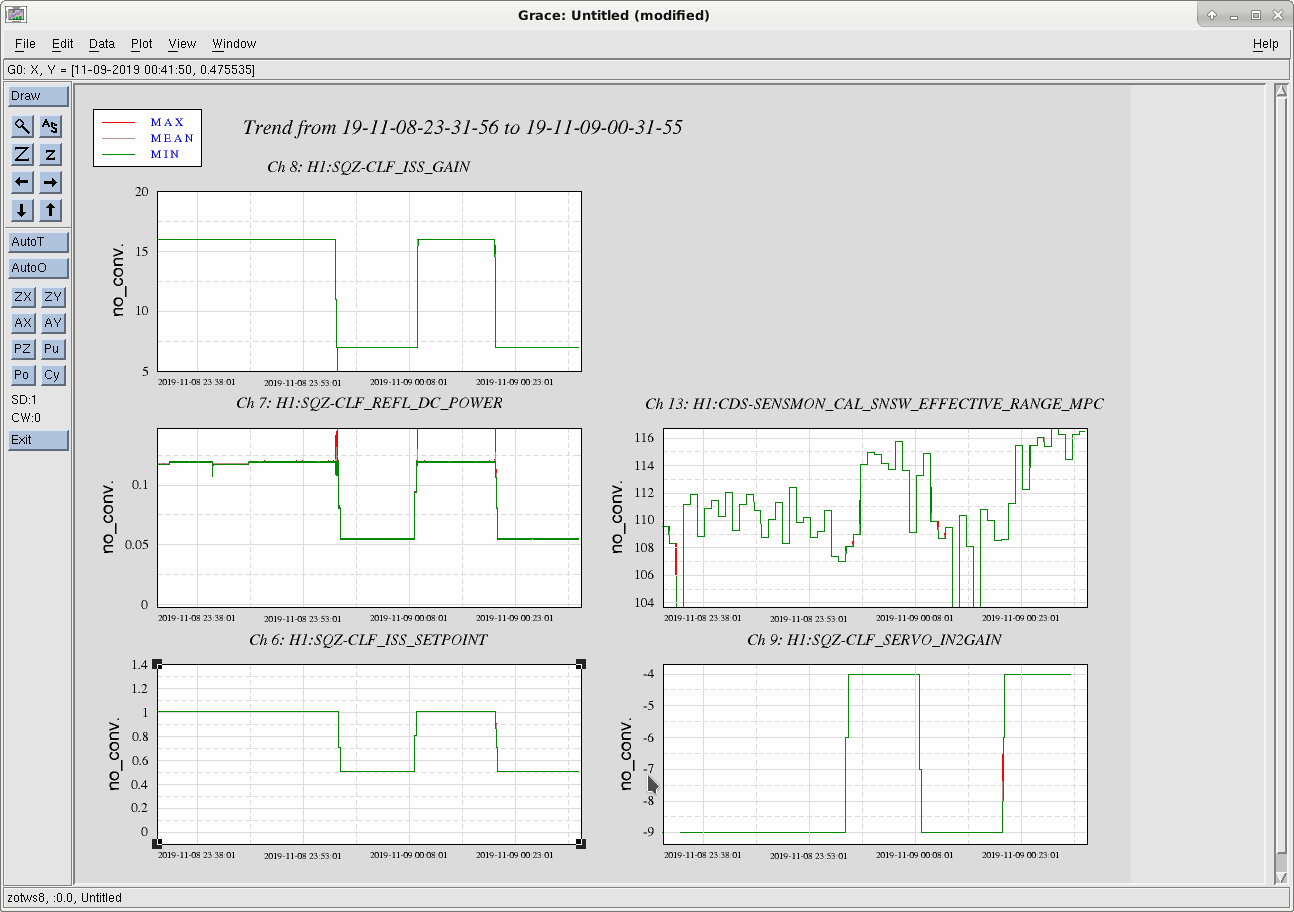
We changed the CLF power from 120µW to 55µW and it correlated with the range!

  120µW  55µW
H1:SQZ-CLF_ISS_SETPOINT 1.01 0.51
H1:SQZ-CLF_ISS_GAIN 16 7
H1:SQZ-CLF_SERVO_IN2GAIN –9 –4

Times:

  1. Change to low CLF power: between 15:57:30 and 15:58:36
  2. Change to high CLF power: between 16:08:30 and 16:09:13
  3. Change to low CLF power: between 16:20:00 and 16:20:40

We accpeted the new settings in SDF and leave it as the new nominal over the weekend.

Images attached to this comment
H1 CAL
jeffrey.kissel@LIGO.ORG - posted 16:59, Monday 04 November 2019 - last comment - 17:22, Monday 04 November 2019(52981)
Calibration Measurements: Sensing Function Suite Today; Sweeps, Broadbands, PCALX vs. PCALY, DHARDP Gain Changes
S. Dwyer, S. Karki, J. Kissel

We've gathered several sensing function measurements today in order to resume the continuing saga of the low frequency regime of sensing function.

The raw data has been committed to the CAL repo here:
/ligo/svncommon/CalSVN/aligocalibration/trunk/Runs/O3/H1/Measurements/FullIFOSensingTFs/
    2019-11-04_H1_NominalConfig_DARM_OLGTF_LF_SS_5to1100Hz_15min.xml
    2019-11-04_H1_NominalConfig_PCALX2DARMTF_LF_SS_5t1100Hz_10min.xml
    2019-11-04_H1_NominalConfig_PCALY2DARMTF_LF_SS_5t1100Hz_10min.xml

    2019-11-04_H1_NominalConfig_PCALX2DARMTF_BB_3min.xml
    2019-11-04_H1_NominalConfig_PCALY2DARMTF_BB_3min.xml

    2019-11-04_H1_DHARDPx1p5_DARM_OLGTF_LF_SS_5to1100Hz_15min.xml
    2019-11-04_H1_DHARDPx1p5_PCALY2DARMTF_LF_SS_5t1100Hz_10min.xml

Sudarshan will aLOG more about the impact of ASC (DHARD P), but I can conclude a few things based on the rest of the data:

(1) The new, 50 ct SRCL offset is not the perfect solution. Comparing 2019-10-31 data with today's data at the same SRCL offset shows quite a different response.
(2) Even though we've updated the PCAL calibrations, PCALX vs. PCALY still seems to be discrepant from each other by a similar small percentage.
(3) Though the optical gain is about the same as the 20190909 reference model, the cavity pole is lower, back down in the 410 Hz region we were back in the beginnings of O3A. 

The > 20 Hz fit results of the PCALY Nominal Config data is
    Optical gain, H_c (ct/m)                 | 3.156e+06 (+1111,-1106) or (+0.0352%,-0.03504%)
    Optical gain, H_c (mA/pm)                | 4.301 (+0.001514,-0.001507) or (+0.0352%,-0.03504%)
    Cavity pole, f_cc (Hz)                   |  410 (+0.7372,-0.7409) or (+0.1798%,-0.1807%)
    Detuned SRC spring frequency, f_s (Hz)   | 0.2008 (+0.1228,-0.06052) or (+61.15%,-30.14%)
    Detuned SRC spring quality factor, Q_s   | 1.655 (+3.894,-4.288) or (+42.5%,-38.59%)
    Residual time delay, tau_c (usec)        | -0.02668 (+0.4573,-0.4558) or (+-1714%,--1708%)

    kappa_c = 0.992245
    f_cc =  410
    f_s = 0.2008 
    Q = 1.655
Remember, our current model has no detuning, and since we fit the data only above 20 Hz, the above numbers for the spring frequency are meaningless. And as we continue to find out, there are many more effects going on at low frequency, so it doesn't make sense to fit the data as "just" an optical spring. But, until we understand what's going on better (and preferably, with that knowledge, just get rid of it), we don't both updating the analysis infrastructure and still "report" a "spring frequency and Q."

The first attachment shows today's nominal config against previous measurements.
The second attachment shows PCALX vs. PCALY measurements of today vs. 2019-08-08 when we last measured the two simultaneously.
The third and fourth attachments show the results of 20-5000 Hz MCMC fit of the data.

Things to do from here: 
(a) Keep measuring the sensing function, to see if there's some SRCL offset that might be better suited.
(b) Understand the PCALX vs. PCALY data, perhaps by invoking the new PCALX vs. PCALY calibration line (see LHO aLOG 51915) to see if the information from that line is consistent with the sweep data.
(c) See Sudarshan's aLOG about the ASC plan.

The plots presented in this aLOG have been created by
/ligo/svncommon/CalSVN/aligocalibration/trunk/Runs/O3/H1/Scripts/FullIFOSensingTFs/
    process_sensingmeas_collection_20191104_SRCLOffsetAgain.py
    process_sensingmeas_collection_20191104_PCALXvsPCALY.py
    process_sensingmeas_20191104.py
which have been committed to the CalSVN repo as well.
Non-image files attached to this report
Comments related to this report
sudarshan.karki@LIGO.ORG - 17:22, Monday 04 November 2019 (52983)CAL

The results of the sensing function measurement with Nominal ASC loop configuration is compared with the sensing function measurement taken with ASC DHARD Gain set at 1.5 times the nominal gain of the loop. The measurement with ASC DHARD gain was interrupted by the Tonga earthqauke so we were able to get measurement upto only 9 Hz. The plots are attached, the first plot is normal calibration freq range and the second plot is zommed in from 3-50 Hz.  For comparison the data from 2019-07-10, when similar measurmenets were made are also overlayed in the plot (LHO alog 50498). These measurements show that the sensing function below 10 Hz depends on some combination of ASC gain and SRCL offset. More thinking and measurements will require to understand this fully.

In future:

1. We would like to get better open loop gain measuremnt of DHARD loop to better understand its UGF and to see if what we are seeing is gain-peaking.

2. See if we can reduce angle to length coupling with frequency dependent A2L filter.

The script used to anlayze these latest measurements are here:

/ligo/svncommon/CalSVN/aligocalibration/trunk/Runs/O3/H1/Scripts/FullIFOSensingTFs/process_sensingmeas_collection_20191104_ascgainchange.py
Non-image files attached to this comment
LHO General (OpsInfo)
thomas.shaffer@LIGO.ORG - posted 16:13, Monday 04 November 2019 (52965)
Ops Day Shift Summary

TITLE: 11/05 Day Shift: 16:00-00:00 UTC (08:00-16:00 PST), all times posted in UTC
STATE of H1: Earthquake
INCOMING OPERATOR: Jim
SHIFT SUMMARY: Lost lock due to an earthquake during calibration measurements. Waiting for the earth to ring down, but attempting to lock green arms.
LOG:


Future Operators: If the squeezer drops and will not relock on its own, bring the SQZ_CLF_LR node to DOWN and then once that state has complete, bring it back to LOCKED. If this doesn't work after a few attempts, then it might be another issue.

H1 DetChar
daniel.brown@LIGO.ORG - posted 15:03, Monday 04 November 2019 (52978)
Phase camera back on

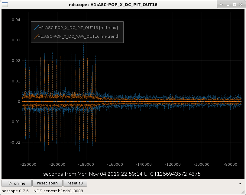
After speaking with Keita we agreed to switch the phase camera back on to try and get some more data before pulling it out tomorrow. It was switched back on at 1:50 PST (1256939418). I have placed a plate between the camera and POPX which on Saturday appeared to fix the scattering shelves we were seeing when the camera forces its internal fan on to cool down, this was happening before every ~2700.  Apart from that, Robert and I could not see any direct coupling into DARM when it was on last week. Although we were concerned about the power supply fans being on so close to ISCT1, hence why it was switched off on Friday.

If the fan does comes on it is quite visible in the POPX DC channels when the plate wasn't in, plot attached: H1:ASC-POP_X_DC_PIT_OUT16, H1:ASC-POP_Y_DC_PIT_OUT16

Images attached to this report
H1 TCS (DetChar)
thomas.shaffer@LIGO.ORG - posted 15:01, Monday 04 November 2019 (52977)
New HWS EY light source ON/OFF test

We need to see confirm that the new 520nm HWS source at EY is not injecting any noise. During the calibration measurements today, I turned it off and on and marked GPS times. I tried to switch it between noisy measurements as best I could. DetChar, can we get your help here?

OFF - 1256940810

ON - 1256941650

OFF - 1256942490

ON - 1256943380

H1 ISC
daniel.sigg@LIGO.ORG - posted 14:11, Monday 04 November 2019 (52976)
IMC VCO tune offset

Found the tune offset of the IMC VCO at -0.015V. We ran at -4.965V in O3a, so I put it back.

Also found the picomotor controllers for HSW and SQZ were on. Turned them off.

H1 DetChar
thomas.shaffer@LIGO.ORG - posted 14:09, Monday 04 November 2019 (52975)
Distant detonations/explosions/demolition heard on site

We are getting reports of what sounds like explosions off toward the Hammer training facility, just as Philippe investigated on Oct. 16 (alog52525). Though perhaps not as loud as that day, it may show up in microphones on site and perhaps the IFO.

Times of reports are 18:24UTC with the bangs about 10 seconds apart. There are also reports earlier than that, but I don't have times.

H1 General
thomas.shaffer@LIGO.ORG - posted 13:58, Monday 04 November 2019 (52974)
Out of Observing 2150 UTC to Start Commissioning/Calibration
H1 AOS (CAL)
vladimir.bossilkov@LIGO.ORG - posted 13:53, Monday 04 November 2019 (52972)
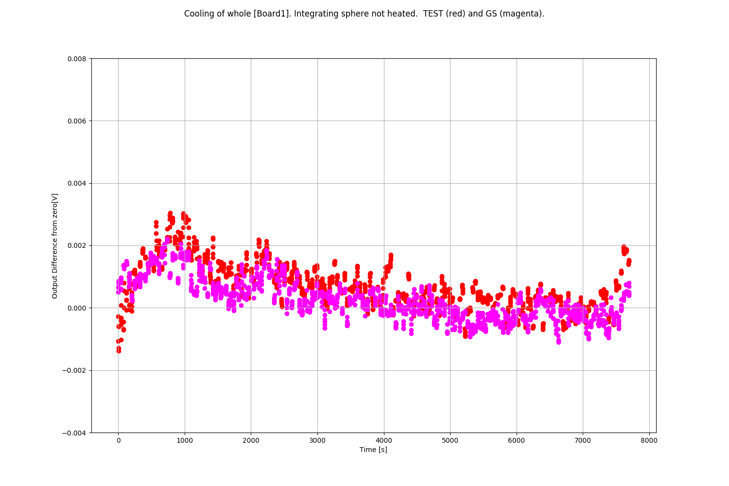
Temperature Dependance in Pcal Photodetectors 2

Vlad, Niko
Continuing from aLog:

Resolved Noise issue of [Exp3, previous aLog].:
    Niko replaced the incorrect Op.Amp, and reinstalled the related capacitor.
    We also checked and found that R2 resistor (resistor across transimpedance amplifier) on this board has been updated to a model with lower temperature dependence.
    Board performed as expected.

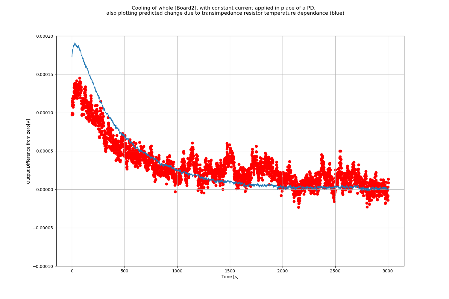
We repeated [Exp3, previous aLog] from the previous aLog with the fixed board:
    [Exp4.png] We observed a temperature dependence that meets the specification of the R2 resistor. The blue line is the calculated voltage change we expect from the resistor. The board has a mounted thermometer which we use to calculate this expected response based on its specifications. The resistor appears to perform slightly better than the specification.
    From this we are confident we know temperature dependence that arises from the PCB board itself - that it is due entirely to the R2 resistor, and that this about 50x less than what we see from [Normal_operation_voltage_change.png].

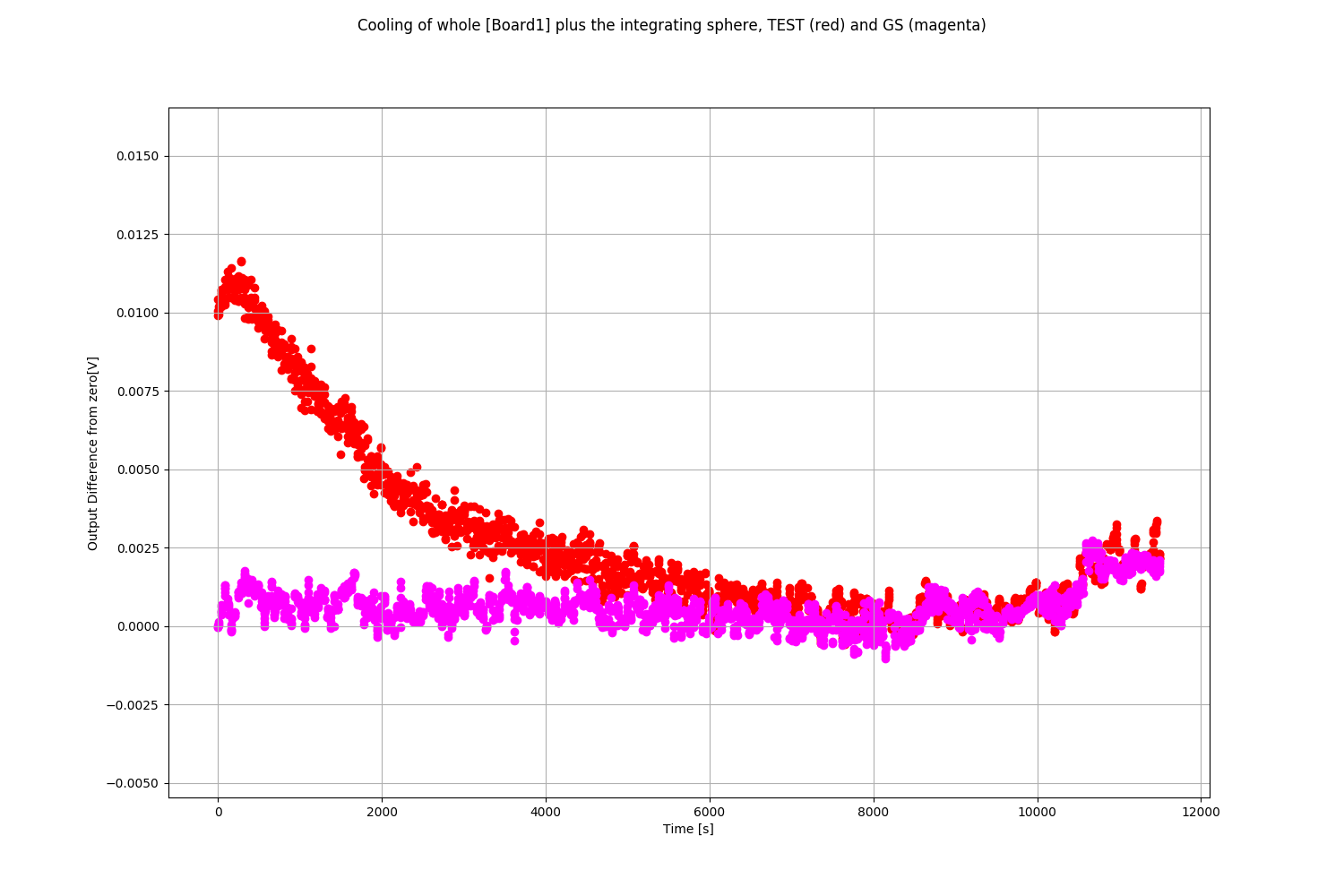
We go back to [Board1] and repeat test against the Gold Standard (GS) in the presence of optical light:
    [Exp5.png] We do observe the expected temperature dependant voltage difference from  [Normal_operation_voltage_change.png].


From here we continue to isolate the problematic component, given a much more limited number of variables:
    [Exp6.png] Here we heat only the black box that sits atop the integrating sphere, and repeat the experiment as above. We don't see any Voltage differences to the (not heated) GS. For this reason we can rule out the black box as being a major factor in temperature dependance of these devices.
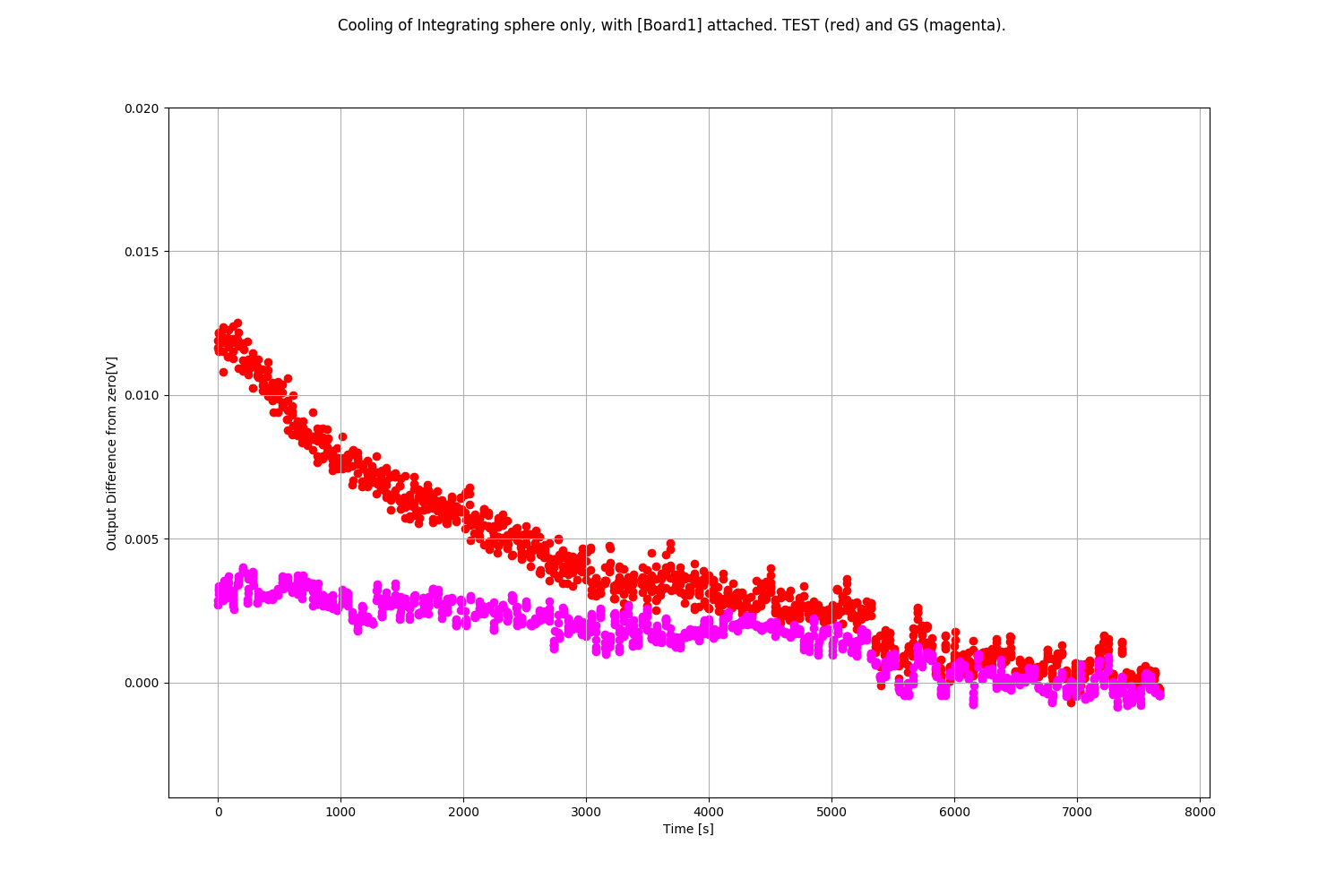
    [Exp7.png] Here we heat only the integrating sphere and not the black box. I plot against the signal seen GS, and we once again observe the temperature dependant voltage difference.
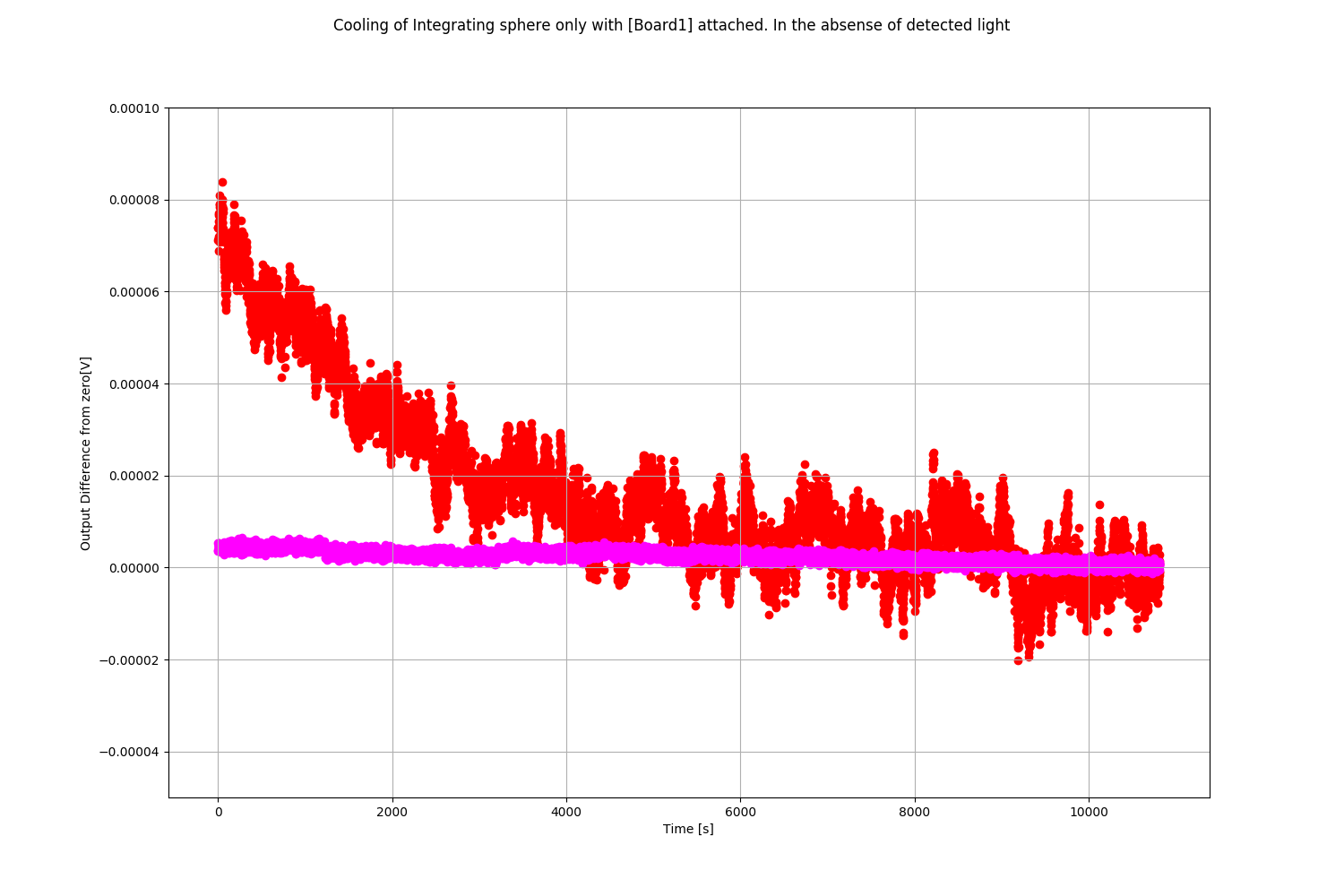
    [Exp8.png] To confirm the result from the previous aLog, where [Exp7] was done in the absence of light, I repeat the above (heat only the integrating sphere) in the absence of laser light. The absolute voltage change is seen about a factor of two stronger than what was seen in the old experiment. Not sure why.

Conclusion for now:
We observe output changes attributable to an integrating sphere temperature dependence (which itself depends on input laser power).

More clever tests need to be designed to continue to understand how and why this works the way it does. It is not currently known why the magnitude of the response depends on whether there is incident light or not, and how the sphere's thermal state is coupling to that and the total output of the calibrators.

I've tried to read about the material in which the sphere is coated in: "Spectraflect".[Datasheet]
    The only thing that jumps out to me is the Laser damage threshold: we would be operating really quite close to that - perhaps this material is very sensitive to thermal effects related to relatively focussed incident power
    Still doesn't fully explain why we see output changes when there is no laser light incident - surely must be some thermal coupling to the PD's longer wavelegnth sensitivty region, and Vlad will attempt to model that.

Images attached to this report
H1 PEM (DetChar)
robert.schofield@LIGO.ORG - posted 19:43, Sunday 03 November 2019 - last comment - 13:17, Monday 04 November 2019(52949)
Vibration coupling still high at HAM5/6; beam spot found on HAM5 side of septum

Philippe, Robert

Summary: We found no evidence of an overall reduction in coupling at the septum, associated with replacement of the main window. This could be because the window was not angled to retro-reflect light from the beam, so additional angling made no improvement. Another possibility is that scattering coupling was not dominated by the window. We found a candidate for the latter explanation: a beam spot on the HAM5 side of the septum. The septum moves more than the ground and is a better reflector than other parts of the vacuum enclosure, so we may want to consider shrouding it.

Figure 1 shows a comparison of coupling before and after the break. Some frequencies look better by factors of 2 or 3, others look worse by similar factors. We don’t know how much of this is due to differences associated with the scaffolding. The average of “before” and “after” coupling factors is about the same. On the whole, I think we can say that any improvement was less than a factor of 2.

We had hoped for more of an improvement, so we checked for other problems by redoing the other measurements that had led us to the septum before the break (none led specifically to the septum window). Figure 2 shows that both the arrival time and the DARM amplitude for impulse injections are still most consistent with coupling near to the septum accelerometer. And, the frequency structure in the signal from the septum accelerometer is still the best match to the frequency structure in DARM.

In addition, we tried the new beating-shakers technique, and preliminary results are also consistent with coupling at the septum.

We photographed the spot on the new septum window. Figure 3 shows the new and old spots and scattering centers on the window. The brightness at 3 degrees was roughly similar to what I had photographed before the window replacement, as determined by camera settings used to capture it. 

One possible explanation for un-improved scattering coupling is that we weren’t getting a specular reflection off of the window, so angling it did not help, and the improvement in window quality or cleanliness did not change the scattering by much.

Another possibility is that there is/was another beam on the septum that dominates the scattering from the septum.  So, we looked again for other beams on the septum. We found one on the HAM5 side of the septum near the central port (Figure 4) that I had not noticed before. I’m not sure whether or not this beam spot was present before the break because I could only see it from the very edge of one view port and from the illuminator port, which I had not used previously. I’m not sure of the origin of the beam spot on the septum. According to camera settings it is quite bright, requiring about the same camera settings as the beam spot from the window, but at a much larger angle than 3 degrees.

Unfortunately, the presence of the spot on the septum makes it difficult to conclude whether or not we must remove the window in order to make further reductions in coupling. I think that one thing we have learned is that we should consider a scheme to shroud the septum further since it moves more than the ground, is highly reflective, and is normal to the beam path.

 

Non-image files attached to this report
Comments related to this report
jeffrey.kissel@LIGO.ORG - 13:17, Monday 04 November 2019 (52970)DetChar, ISC, PEM, SYS
Tagging @SYS, in case they can help us identify /confirm from where this beam comes. 
Is it coming from the OFI on its way to the OPO? Is it the ghost beam that's coming from the OFI that nominally should be dumped and is no longer dumped?
H1 General
cheryl.vorvick@LIGO.ORG - posted 17:13, Sunday 03 November 2019 - last comment - 06:41, Tuesday 05 November 2019(52946)
OPS Day Summary

TITLE: 11/04 Day Shift: 16:00-00:00 UTC (08:00-16:00 PST), all times posted in UTC
STATE of H1: Observing at 115Mpc
INCOMING OPERATOR: Patrick
SHIFT SUMMARY: H1 in Observe, instrument air pumps for LVEA are working, SQZ just fixed itself, causing an increase in range
LOG:

VACUUM:

SQZ:

Comments related to this report
cheryl.vorvick@LIGO.ORG - 08:55, Monday 04 November 2019 (52961)

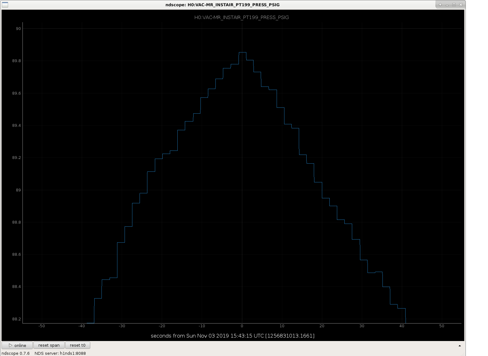
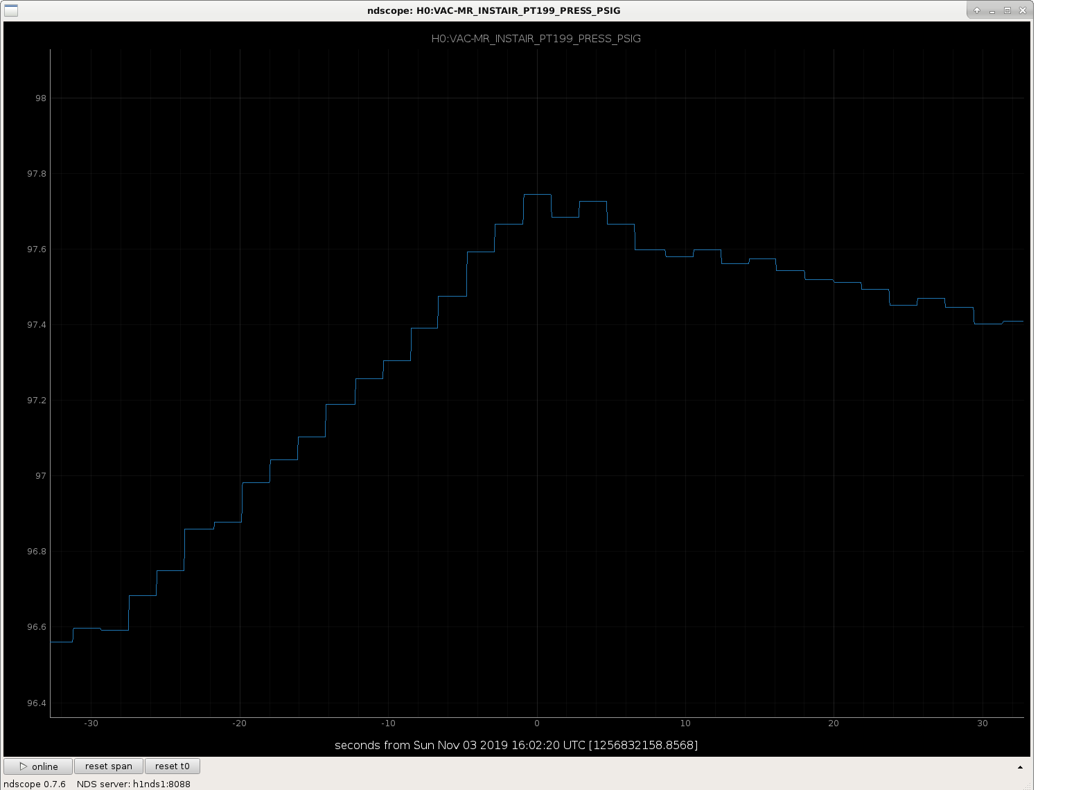
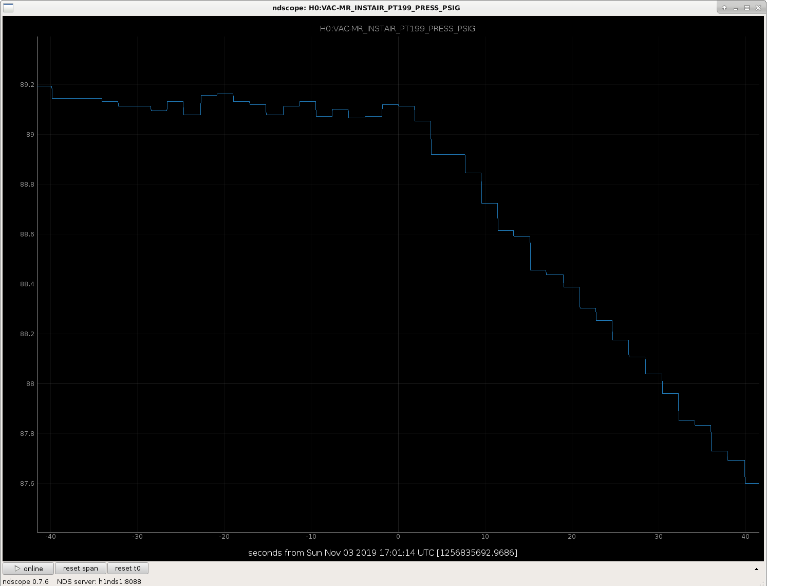
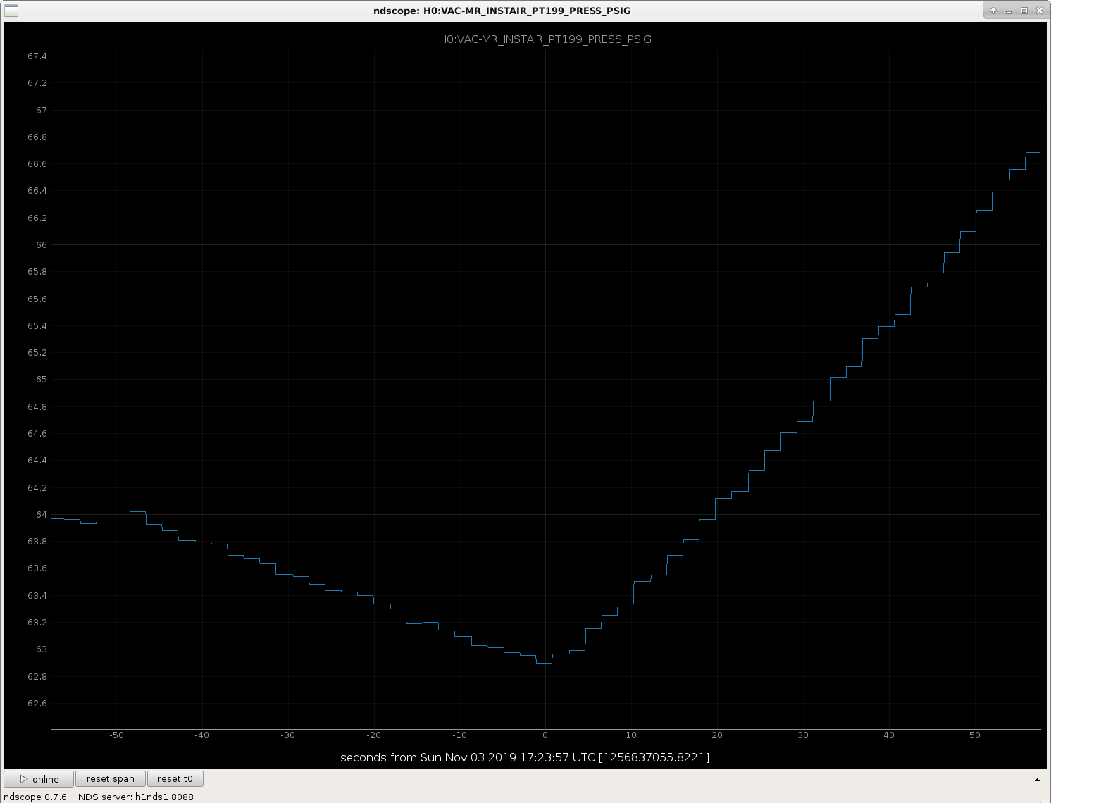
Images that go with the PT199 timeline:

Images attached to this comment
cheryl.vorvick@LIGO.ORG - 09:02, Monday 04 November 2019 (52962)

An interesting plot showing an alignment change in ZM2 yaw that coincides with the increase in H1 Range.

Images attached to this comment
jeffrey.kissel@LIGO.ORG - 13:21, Monday 04 November 2019 (52971)DetChar
Tagging @DetChar on this one -- these distinct range changes are still a mystery to the on-site team. 
Perhaps comparing BRUCO's (looking for linear coherence) or LASSO's (looking for slow changes that correlate to the times of distinct change) around these times might reveal some smoking guns?
Any help is appreciated!
beverly.berger@LIGO.ORG - 06:41, Tuesday 05 November 2019 (52998)DetChar

The LASSO results for 4 Nov (see https://ldas-jobs.ligo-wa.caltech.edu/~detchar/summary/day/20191104/detchar/lasso/) show a strong correlation between SQZ channels (perhaps excited by seismic motion) and the range drop. Similar results exist for 1 Nov, the most recent prior day with a long lock crossing the range drop. 

H1 CAL (CAL)
timesh.mistry@LIGO.ORG - posted 20:46, Monday 28 October 2019 - last comment - 13:52, Monday 04 November 2019(52751)
DARM Anti-Spring is Back!

[Sheila, Craig, Timesh]

Cal SVN root: /ligo/svncommon/CalSVN/aligocalibration/trunk

This morning, Sheila took the usual sweep of measurements for calibration at around 15:56:49 UTC. When looking at the results from the processing sensing script, we see an antispring at f_s = 4 Hz. Attached to this alog is the raw data, the MCMC model with the measurement, the reference model with all the measurements and MCMC corner plot of this measurement.

We tried to re-measure the the Open Loop Gain (OLG) at around 01:10:13 UTC during which, the PCAL measurement ran successfully however the OLG measurement failed due to an earthquake. Before re-running the measurement we set H1:LSC-SRCL1_OFFSET from 100.0 counts to 0.0 counts. The steps in offset was to make sure that there was not a large loss of power in the arms and have the ability to quickly restore the IFO if required. The motivation for changing the offset was that in O3a, a value of 100.0 counts was used to compensate for a pro-spring (for example, see LHO alog 51440 and comment therein) and since we are measuring an anti-spring with the same counts offset, we may have been driving an anti-spring. The hypothesis is that by removing the offset, the spring would tend towards zero.

We were able to collect OLG data from 1083.7Hz down to 10.334Hz before the lockloss. This is not sufficient for re-measuring the spring/anti-spring of the IFO thus, we will attempt to repeat the OLG measurement once the IFO is back into nominal low noise (NLN) and has thermally equilibrated. The dtt files and processing scripts that were used are given below for the original measurements and the re-run measurements (svn revision given in brackets):

Measurements

Sensing:
^/Runs/O3/H1/Measurements/FullIFOSensingTFs2019-10-28_H1_DARM_OLGTF_LF_SS_5to1100Hz_15min.xml    (r8632)
^/Runs/O3/H1/Measurements/FullIFOSensingTFs2019-10-28_H1_PCALY2DARMTF_LF_SS_5t1100Hz_10min.xml    (r8632)

^/Runs/O3/H1/Measurements/FullIFOSensingTFs2019-10-28a_H1_DARM_OLGTF_LF_SS_5to1100Hz_15min.xml    (r8632)
^/Runs/O3/H1/Measurements/FullIFOSensingTFs2019-10-28a_H1_PCALY2DARMTF_LF_SS_5t1100Hz_10min.xml    (r8632)


Actuation:
^/Runs/O3/H1/Measurements/FullIFOActuationTFs/2019-10-28_H1SUSETMX_L1_iEXC2DARM_10min.xml    (r8632)
^/Runs/O3/H1/Measurements/FullIFOActuationTFs/2019-10-28_H1SUSETMX_L1_PCAL2DARM_8min.xml    (r8632)
^/Runs/O3/H1/Measurements/FullIFOActuationTFs/2019-10-28_H1SUSETMX_L2_iEXC2DARM_12min.xml    (r8632)
^/Runs/O3/H1/Measurements/FullIFOActuationTFs/2019-10-28_H1SUSETMX_L2_PCAL2DARM_6min.xml    (r8632)
^/Runs/O3/H1/Measurements/FullIFOActuationTFs/2019-10-28_H1SUSETMX_L3_iEXC2DARM_12min.xml    (r8632)
^/Runs/O3/H1/Measurements/FullIFOActuationTFs/2019-10-28_H1SUSETMX_L3_PCAL2DARM_6min.xml    (r8632)

Processing

Sensing:
Reference model: modelparams_H1_20190909
^/Runs/O3/H1/Scripts/FullIFOSensingTFs/process_sensingmeas_20191028.py    (r8636)

Actuation:
Reference model: modelparams_H1_20190416
^/Runs/O3/H1/Scripts/FullIFOSensingTFs/process_actuationmeas_20191028.py    (r8637)


Non-image files attached to this report
Comments related to this report
timesh.mistry@LIGO.ORG - 12:22, Tuesday 29 October 2019 (52756)

[Craig, Timesh]

We re-measured the sensing by re-measuring the OLG and PCALY. Before re-running the measurement we set H1:LSC-SRCL1_OFFSET from 100.0 counts to 0.0 counts.  The Earth stayed quiet enough that we now see a ~9Hz pro-spring after the successfully completion of both measurements. Once again the raw data, the MCMC model with the measurement, the reference model with all the measurements and MCMC corner plot of this measurement are attached to this alog.

I am uncertain what the reason is, or the cause of, the pro-spring/anti-spring in these scenarios.

Non-image files attached to this comment
jeffrey.kissel@LIGO.ORG - 19:46, Tuesday 29 October 2019 (52787)
I'm not confident that the above 0ct SRCL offset data is really a "9 Hz pro spring," and Sheila and I are not so confident it's really bad just yet. (Where "bad" would be "enough of a low frequency response that would drive us to change the sensing function model in the front-end.")

I've compared the above two data sets against the last few data sets of O3A in the attachment below.

One can see that, although, indeed a 100 ct SRCL offset is an anti-spring, the 0 ct offset data residual looks much like the subtle residual mixing of a detuned SRC and some sort of L2A2L crosscoupling (or whatever label you want to put on the as-of-still-poorly-understood low frequency response that's *not* a detunement of the SRC) that we saw at the tail end of O3A *after* installing the 100 ct offset.

Also note that there's no magic to the numbers here: they're all determined by "quick" tests -- easy changes in the IFO configuration that need confirming with ~25 minutes of measurement. We started with no digitally requested offset (0 ct) for most of O3A, and then on one Wednesday after sorting out our August spot position kerfuffle, we tried 100 ct, then 200 ct to try to reduce the severe pro-spring with which we ended up. 200 ct seemed unstable, and 100 ct conveniently seemed to give us the "no detuning" response we wanted. Now, the quick test was "turn it off," and *that* got us close enough, so we're running with that for now. Sadly, we've yet to put together a model that's complete enough to help us understand and/or predict what's going on.

So, for now, if we can get the IFO stable enough for us to have the patience to do some more exploring, we'll measure the sensing function again to make sure this new answer -- with 0 ct SRCL offset -- is consistent, or if the resulting low frequency response moves around with time.
 
Non-image files attached to this comment
jeffrey.kissel@LIGO.ORG - 13:52, Monday 04 November 2019 (52973)
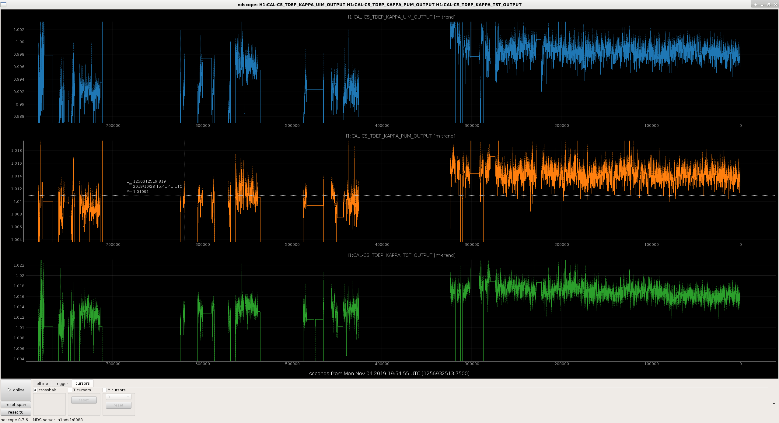
Taking a look at the work Timesh did to process the 2019-10-28 actuator data, the answers are

                           UIM                     PUM                    TST          
Reference Model         7.67e-08 (N/ct)         6.036e-10 (N/ct)     4.727e-12 (N/ct)
MCMC Fit                7.564e-08 (N/ct)        6.065e-10 (N/ct)     4.781e-12 (N/ct)
kappa via MCMC          0.986054                1.00483              1.0115
kappa via CALCS         0.995                   1.0107               1.0133

So these should be close enough that we don't need to update the actuator coefficients. 

Note that these will have similar 0.5% levels of systematic error that have been reported by the PCAL system in 52893 from having the wrong ETMX test mass mass. To be determined how we'll rectify this....
Images attached to this comment
Non-image files attached to this comment
Displaying reports 37681-37700 of 89095.Go to page Start 1881 1882 1883 1884 1885 1886 1887 1888 1889 End