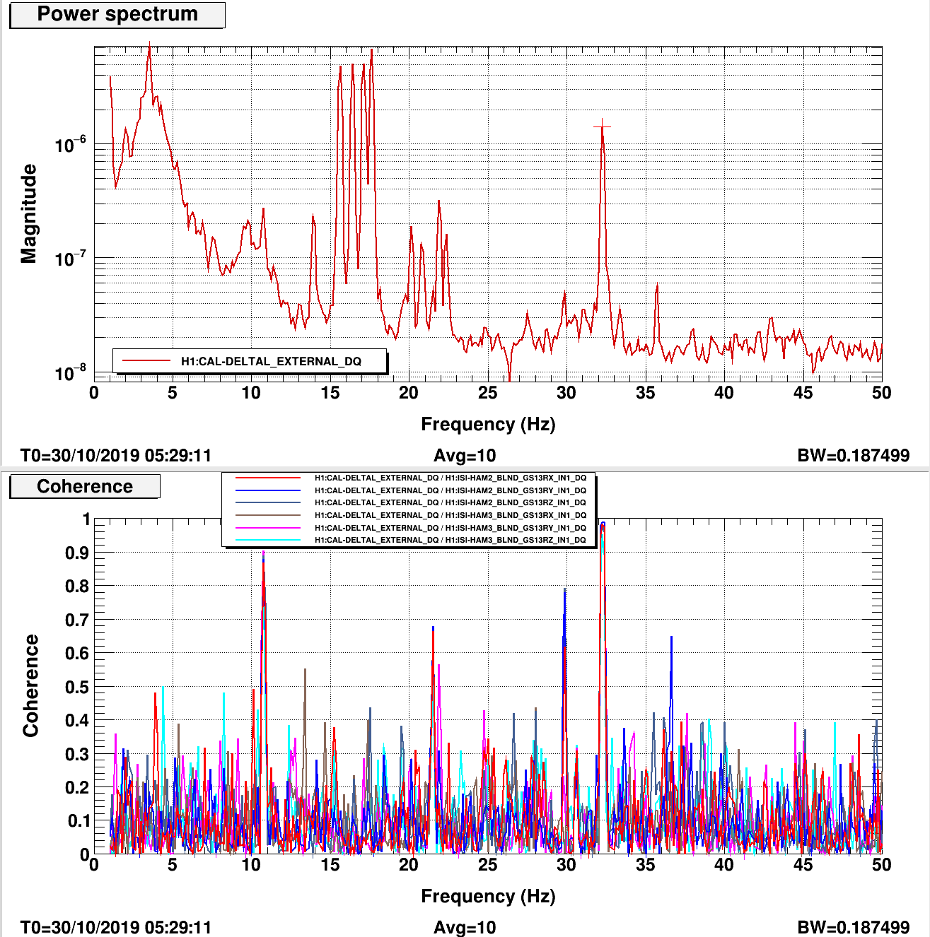
For the brief period that we were locked at NLN today we noticed the 32 Hz line in DARM was much larger than before. I happened to have a HAM shaking template open and noticed that the line was also seen in sensors in HAMs 2 and 3 (first attachment).
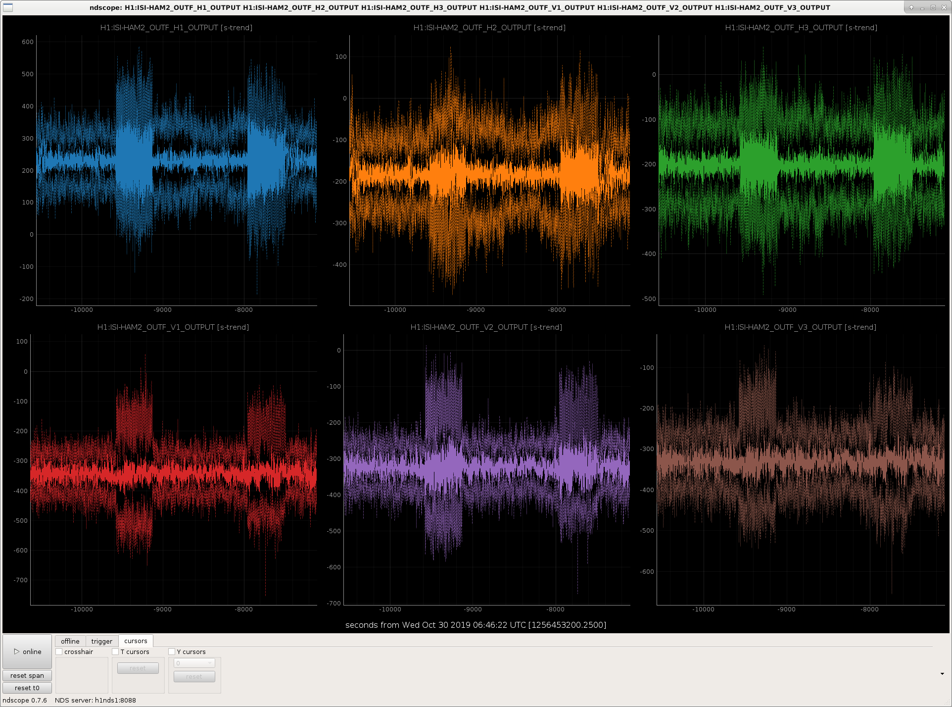
Looking at the time series, there has periodically been extra noise in both HAM ISIs since ~last Wednesday (second attachment).
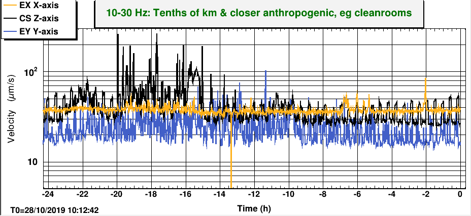
Dan noticed that a noise with the same periodicity is seen in the anthrogogenic band ground motion FOM, in the corner stations z axis (third attachment).
Does anyone know what this noise is?
We are having problems powering up. The problem happens while the rotation stage is rotating to increase power incident on the IMC. To compensate our analog CARM and IMC loops for the increase in optical gain, we decrease the analog gain using the H1:IMC-REFL_SERVO_FASTGAIN slider. This slider goes in steps of 1 dB, so it's not exactly a smooth ride, but usually it's fine. Now it is not. Dips in power everywhere after the IMC (MC2 trans, MC4 trans, PRG) are associated with some, not all, FASTGAIN steps. It's not clear what changed. This wasn't a problem Saturday or Monday. I checked the IMC and CARM OLGs just before we power up (attached), and both looked fine. We tried decreasing the CARM gain on H1:IMC-REFL_SERVO_IN2GAIN by 3 dB (from -22 dB to -25 dB) just before running MAXIMUM_POWER, to test if the three UGFs in the CARM loop was the problem. It was not, the decrease in CARM gain did not help with the power glitches. (btw CARM has three UGFs because at ~20 kHz the 9 MHz sidebands become resonant in CARM, increasing the CARM plant gain. This is why the loop wins phase there.) Anyway, the "ISS troubles" from earlier were the symptom that kills us. Jenne moved the second-loop turn on to after powerup, so the ISS no longer immediately ends the lock. Unfortunately, other lock-enders include the ADS system, whose output is not limited during powerup and is susceptible to large glitches (the impulse causes the ADS lowpasses to accumulate to push the IFO off alignment).
We lost lock, probably due to a brief loss of the PRC2 error signal. I took a MCL crossover, things are increased overall compared to the old reference, which was probably taken at full lock, but nothing too dangerous with 30 degrees of phase margin. On relock, we tried to increase the IMC gain by 2 dB. On the second click, IMC REFL camera immediately became far brighter, so I retreated the gain slider. We basically triggered a power glitch by raising the IMC gain, seen in MC2 trans, etc. After my heroic save of the lock I almost killed, we decided to lower the IMC gain by 2 dB. This solved our powerup power glitches problem. Likely, the IMC UGF was getting too close the phase = 180 deg point at 100 kHz while we were adjusting power. We are continuing to try to lock. We lost at LASER_NOISE_SUPPRESSION, the next state that tries to adjust these gains. None of this is in the guardian yet. (If anyone knows how to rotate pdfs made by diaggui that would be great. I've tried like three different methods unsuccessfully.)
Adjusted CARM_TO_ANALOG (ISC_LOCK line 2322) such thatezca['IMC-REFL_SERVO_IN1GAIN'] += 1 # from -1 to 0 dB, CRC 20191030rather thanezca['IMC-REFL_SERVO_IN1GAIN'] += 3to push the IMC gain down. This state works. Put the +2 dB of IMC-REFL_SERVO_IN1GAIN gain back into LASER_NOISE_SUPPRESSION. Hopefully this will avoid the CARM gain increases here colliding with the IMC, so LASER_NOISE_SUPPRESSION will no longer cause locklosses. EDIT: it worked
For when the IFO gets back up, here is the script we'd like to run to rotate through squeezing angles. Modified from Sheila's verion to adjust LO loop gains to stay stable.
python /ligo/cds/lho/exports/lee.mcculler/squeezing-measurements/script_IFO_phase_gain.py
it is also attached. It will make a 'logs' directory where it is run and output a log of the gps times at rotations.
Started script on zotws12 at 11:01 UTC
Lockloss at 22:44 was from squeezer starting a seeding measurement. The LO loop was disabled, but the integrator/boosts weren't disabled first. The output ran away and pushed some sideband through the IFO carrier. It shouldn't have range now to push the CLF through IFO carrier, so perhaps there is something else lurking. Should investigate this with homodyne LO. The servo hit the +10 rail.
Anyway, for seeding/backscatter measurements with IFO, disable the boosts first.
[Chiara, Jim, Jenne]
We added senders and receivers to the seiproc model so that we will also eventually be able to do CPS_DIFF stuff between the test masses, which we hope will help with earthquake and windy times. (The ETM ISIs needed restarting anyway, to pull in a bug fix that the vertex ISIs got some time ago). We also added receivers and switcher matrices, so that we can do the PRCL, MICH, and SRCL offloading either using the sus M1 outputs or the calibrated LSC signals. This required restarting the PRM, BS, SRM sus models.
Also, I've updated and tested the SEI_DIFF guardian, and it reliably can turn on and off the CPS portions of the SEI DIFF system (which are the only parts we're using so far without one of us watching).
I wrote a small script to do an on/off test that hopefully someone can run tonight - it'll run for 6 hours, but is fine for someone to ctrl-c out of if needed.
>> python /ligo/home/jenne.driggers/LHO_work/2019_10_28_ISI_MC2_DIFF_TF/Change_SEI_DIFF_guardian.py
[DanielS, Jenne, Craig, Georgia, DanB, Cao]
Earlier today, there were tests with the second loop during IMC-only times going up to high power and back down, and that seemed to be just fine. So, it's unclear why we're having problems with the same settings but the IFO is on.
Daniel noticed that we seem to be losing the ISS when the second loop tries to reclose after having opened due to a saturation (not so surprising - we know we can't close the ISS second loop at high power). We're still not sure why we're getting a glitch that is causing a saturation, but for our current lock we've removed the checker that opens the ISS, to see if we can sneak through the power-up.
----> No good. We lived through the first glitch, but failed on the second glitch a second or two later. It looks perhaps like the AC coupling loop is going unstable, although you'd think that we'd see this as a problem during the IMC-only tests.
Daniel "changed some parameters" and thinks that the AC coupling should be more "balanced", so we're trying to power up again. We're still seeing glitches that the guardian responds to by opening the second loop, but then it seems to be able to reclose more smoothly. So far it's working, and we got to 20W okay.
----> Going up past 20W didn't work. Looks like maybe we could try waiting longer after the ISS second loop is turned off before turning it back on, so that the loop has a chance to recover from the transient that happened when the loop opens.
This lock, we're going to try going all the way to full power, and then engaging the second loop. Since we've been able to close the second loop several times during power up last lock as guardian noticed saturations and opened the loop, perhaps we can close it for the first time at full power.
----> We got to 20W again okay, although we see the same spikes up in PRG that we had been seeing at the same time that the ISS was being bad during the last few locks. Rotation stage doing something funny when it starts or stops moving? But we're not seeing anything weird in the IMC transmitted power, which I'd expect to see if there was a problem with the rotation stage. We're going up to max power, but the glitches make DARM drown out the ADS lines, so I turned off the ADS loops during the last part of powerup. We were able to get to 37W.
----> Georgia sees strange glitches in IM4 trans and MC2 trans, although it is still not in the power readout on the PSL table.
----> Craig just plotted the IMC-REFL_SERVO_FASTGAIN, and it's clear that the glitches are happening when the gain is changed to compensate for the higher power. Craig also points out that if the CARM gain is marginal (too high, or too low), then we'll expect to be more suceptible to these kinds of glitches in the IMC/CARM loops.
----> We were able to close the ISS second loop after we had completed the Maximum_Power state! (I just selected ISS_ON in the IMC guardian after we had arrived at and completed MaxPower in ISC_LOCK.) Hooray! As DanB put it "that was surprisingly uneventful".
----> We are now at Nominal Low Noise (without the squeezer). Squeezer team has the IFO to inject squeezing, optimize, and do some of the before-Friday measurements.
Separate note on alignment: The alignment seems to be deteriorating. It's taking a little longer each lock for DRMI to acquire. Although, 'longer' has meant 2-4 min, rather than less than 1 min that we've been having all afternoon, so I feel bad complaining too much!
S. Dwyer, J. Driggers, S. Dwyer, J. Kissel, N. Lecoeuche, T. Shaffer, D. Sigg Recovery after maintenance today was pretty rough. The following disparate reasons were the cause of the trouble thus far, and we're not yet back in business. We started attempting to recover around 12:30p PDT. At the moment, we're close to (mostly) nominal low noise, but having problems with the ISS 2nd loop once we request past 20-30W of PSL output power. (1) Upon starting initial alignment with the green arms, Niko and I were immediately stumped by the ALS ARM guardians complaining about errors with their PDHs and PLLs. Daniel saved us on this one, with some details in LHO aLOG 52784. See his aLOg for explanation of what is happening -- anew systemic problem as a result of the new way to pick off the ALS fiber power from prior to the ref cav. His solution was to set laser crystal frequencies (e.g. H1:ALS-X_LASER_HEAD_CRYSTALFREQUENCY) to be some value close to its nominal. (2) After recovering the ETMY platform from the model restarts that happened today (see LHO aLOG 52768), we forgot to turn on the damping loops of the SUSTMSY, before attempting to restore the ISI to FULLY ISOLATED. This rung up some interaction between the two, and tripped the platform hard a few times. Once figured out and fixed with everyone damped and isolated as per normal, ALSY needed a lot of help in alignment (many mircoradians in pitch) before we saw any flashes. But, once Niko had the patience to iterate long enough with the TMSY and ETMY alignment, we were able to restore things enough for the greenWFS to take over. (3) Our next stumping point after initial alignment of the green ams was done, was the failure to repair the HAM6 PT110 pressure sensor today (LHO aLOG 52775). This sensor was serving as our high voltage interlock sensor, so since it didn't work suddenly near the end of maintenance, it tripped the high voltage off. Since the high voltage was off, the fast shutter was closed, which meant that the QPDs at the AS port (AS_A, AS_B, AS_C) were blocked, and the input alignment wouldn't work -- with the symptom being that the ASC DC centering loops were railing. It took Jenne putting two-and-two together to understand this connection path as to why the automated ALIGNING_INPUT step wasn't progressing. TJ has now added a check for the fast shutter being open during this step to the automated initial alignment guardian so that we don't get bit by this again. (4) The final problem with Initial alignment was with aligning the SRC cavity. Sheila reports that there has been trouble with SRY (the IFO DOF used during initial alignment to align SR2 and SRM) since the recovery, in that it needs more length loop gain. The symptoms of the problem were that SRM was getting blasted and saturated by the LSC control, and the SRC alignment control signals were quite non linear. It's unclear if the saturated SRM was really a problem though, because smoourshing SRM hard tricked the INIT_ALIGN automated guardian in to thinking that SRM was *misaligned,* and thus began the "SRC is really misaligned, so I'll do the 'misalign SRM and adjust SR2 alignment' trick," and ended up slowly but surely bringing the SRC in to alignment. Regardless, Sheila added some more gain in SRY length loop in to the initial alignment guardian step. We don't have any clues yet as to why SRY needs more gain that it used to. (5) Once past initial alignment, we got stumped on locking DRMI. The symptom was very low/small flashes in PRMI. We did the typical "shoulder shrug" redo of initial alignment, but to no avail. Once back to the same point we tried manually searching the BS and PRM all over the place for better flashes, questioning IM4 and PR3's alignment, the path of "look at the error signals" led us to suspecting REFLAIR9, whose DC light signal was really low. From there, we looked at the REFL camera image and saw next to nothing. Then we remembered that we haven't locked up the IFO since the phase camera work last night on ISCT1 -- the same table on which REFLAIR9 lives. Turns out it was that phase camera work mitigating scattered light (see LHO aLOG 52759): they had placed beam dumps in lots of locations in order to mitigate the scattered light, but did so during (mostly) nominal low noise (no squeezer), when we've got the REFLAIR path shuttered from in vacuum. Thus a dump inadvertently ended up right in the middle of this REFL path. As soon as a particular dump was removed, the camera image and light level on REFLAIR9 DC restored, and PRMI / DRMI locked up quite smoothly. (6) We lost lock a few times during DRMI and/or it was a rocky turn on. In ENGAGE DRMI ASC state, we turn on SRC1, then an integrator to MICH, and then 5 secs later turn on SRC2. But our impression is that SRC1 and SRC2 should come on at the same time. Moved SRC1 engagement, into the next counter step, so the engagement order is now MICH integrator, then 5 seconds later SRC1 and SRC2 are engaged. This has been loaded in the guardian and confirmed successful once. Not sure if this'll fix such lock losses permanently, but we'll try it with this. (7) Now, we're dealing with 2nd loop ISS problems. Once the request for PSL power up reaches past 20-30 W, the ISS 2nd loop freaks out, opens, closes, goes crazy, and kills the lock. Jenne and Daniel are now investigating, and will aLOG what they find (hopefully a solution!).
Main points:
Longer winded:
I started the day out with work station issues, this slowed me way down and killed a large chunk of my time. I went to check for a return beam but did not find anything when I streamed the image, but only after I had stopped the code and removed the HWS plate. I then checked the irises and saw that the beam was not passing through most of their centers. I adjusted it so the beam was passing through all of the irises and then found a return beam quickly after. I moved ETMY by 20urads back and fourth, and tried to minimize the movement seen on camera. This didn't work great, but I wasn't getting a ton of motion so I moved on.
I added in the new 533nm bandpass filter to filter out the ALS junk light that makes it through the PBS. This seemed to work well, see attachment. I also hooked up the cable that the EE guys set us up with, so now we can turn the laser on and off remotely.
We still need to test this with higher power tonight. I'm sure it could use a bit more tweaking, but I ran out of time.
Attachments:
The end station laser locking ran away when the reference cavity was unlocked earlier today. When PSL tries to relock the reference cavity it searches for a resanance by changing the PSL frequency substabtially. The end station lasers try to follow but eventually lost it and went into lala land.
In the past this didn't happen because the end station laser locking would automatically pause, when the reference cavity was unlocked. When we changed the PSL fiber pick-off, we moved the monitor PD as well and it now just monitors the power after the PMC. The PD after the reference cavity is still there, so we should conect it to a spare channel in the auxiliary signals concentrator 3.
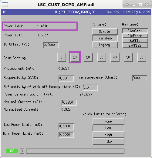
The PSL reference cavity transmission PD was hooked up to a spare channel and the software was updated accordingly.
Channel names are H1:PSL-REFCAV_TRANS_DC_POWER and similar.
The normalized current of this new PD channel is sent to the ALS and SQZ lasers for determining the locking conditions. The threshold has been set to 0.3. So, when the refernce cavity looses lock, these laser locking servos will now pause.
RGA scans were collected before and after venting the corner station in October. All scans are in SEM mode and attached with notes below.
I was concerned about the HC signature shown in Oct. 23 post-vent scan, so today I cycled GV 1,2,5,7 to isolate a potential problem; all scans look satisfactory compared to Oct. 23. The BSC 7,8 doors were cleaned on site, air baked and FTIR sampled. Today we received the pre-bake, post-clean FTIR results from JPL (E1900244) showing some low level residue, but mostly within the LIGO spec of 0.02 microgram/cm^2. The non-vacuum threaded holes used for rigging are extremely contaminated even after Kyle and Chris' best attempt at cleaning them with wand, due to vendor accidentally using silver anti-seize grease. Note that the serial numbers of plates were accidentally stamped on vacuum side. SN001 is on BSC8 and SN002 is on BSC7.
Both plates were sampled with FTIR kit after air baking at 150C for 48 hours; results from JPL were within LIGO specs (<0.02 microgram/cm^2) and received before installing plates (E1900248).
Based on pre and post vent RGA scans from October vent, I conclude that the two scans that look bad are because the filament was not fully warmed up. It should be energized for at least an hour before scanning.
GV 1,2,5,7 were soft closed at various times starting at 9am during today's experiment and RGA scans collected about 1/2 hr after each valve change (filament has been on since yesterday at least). RGA is located between HAM 4 and 5. GV 1,2 took 4:39 min. to soft close (48" valves). (44" valves take 4:18-4:23 to soft close). GV 5,7 soft closed with 5 psig pressure applied to piston.
Bubba G., Tyler G.,
Newly fabricated and Class-B cleaned aluminum HAM door "shipping" covers installed on HAM11
Tyler G., Kyle R.
Shut down Kobelco compressor and chilled water booster pump
TITLE: 10/29 Day Shift 15:00 – 23:00 (08:00-16:00), all times posted in UTC
STATE of H1: Planned Engineering
INCOMING OPERATOR: None
SHIFT SUMMARY: Maintenance ran into a few hiccups with the PT-110 electronics swap not working and the BRS heater not heating. Locking in earnest began around 2pm, but we are back to initial alignment after not being able to acquire PRMI.
LOG:
14:30 (07:30) Hugh to Optics Lab -- fume hood work
14:42 (07:42) Vanessa to LVEA
14:59 (07:59) Karen to EY
15:00 (08:00) Jeff to End stations -- check HEPI pumps, dust monitors
15:00 (08:00) Vlad to Optics Lab
15:45 (08:45) Jim, Fil to EX -- BRS heater work
15:51 (08:51) Chandra to LVEA -- replace PT-110, soft close GV1/2
16:00 (09:00) Richard, Patrick to EY -- check ESD driver
16:11 (09:11) Karen leaving EY
16:12 (09:12) Jeff to EX -- continue HEPI pump/dust monitor checks
16:26 (09:26) Timesh to Optics Lab
16:44 (09:44) Phillipe, Gavin to EX, EY -- test PEM coils
16:46 (09:46) Jeff back from EX
16:59 (09:59) Chandra to LVEA -- soft close GV5/7, open GV1/2 for RGA scan
17:17 (10:17) Richard, Patrick back from EY
17:21 (10:21) Dave, Timesh to EX -- Ncal installation prep
17:32 (10:32) Dick to CER -- RF leakage work
17:33 (10:33) Jason to PSL enclosure -- PMC tuneup
17:51 (10:51) Richard to LVEA -- test PT-110 gauge
17:52 (10:52) Gavin back from EX
17:56 (10:56) Chandra to LVEA -- soft close GV5, open GV1, test PT-110
18:00 (11:00) Marc to CER -- work with Dick
18:22 (11:22) Marc out of CER
18:39 (11:39) Phillipe back from EX/EY
18:40 (11:40) Phillipe to LVEA -- check cables
18:58 (11:58) Phillipe out of LVEA
19:00 (12:00) TJ back from EY
19:12 (12:12) Robert, Phillipe out of LVEA
19:21 (12:21) Nutsinee to LVEA -- log out of computer
19:28 (12:28) Kyle out of LVEA
19:28 (12:28) Nutsinee out of LVEA
19:44 (12:44) TJ to LVEA -- sweep
19:55 (12:55) Richard to LVEA -- turn off transformer
19:57 (12:57) Timesh to Optics Lab
20:04 (13:04) Richard out of LVEA
20:30 (13:30) Kyle to LVEA
20:54 (13:54) Jeff finished moving chemicals
21:01 (14:01) Richard to CER -- check on HV bypass
21:32 (14:32) Timesh to Optics Lab
22:12 (15:12) Jim back from EX
22:27 (15:27) Nutsinee to SQZT6 -- replace diode
22:47 (15:47) Timesh to Optics Lab
23:02 (16:02) Nutsinee out of LVEA
Follow-up to entry made last night -> Adjustments made look good. PT199 values ranging between 67 - 92 psi (much improved). No more "experimenting" required.
Fil C., Richard M., Kyle R.
We are temporarily utilizing a contact closure provided by the 10 L/s ion pump controller (local to the newly installed RGA assembly) as an interium solution for the high voltage pressure interlock in HAM6. Normally, this contact closure is provided by PT110. However, PT110 is out of service until further notice.
Details:
It was noted, while PT110 was still working, that an indicated pressure of 9 x 10⁻⁷ torr given by PT110 corresponded to a pump current-converted pressure of 4 x 10⁻⁷ torr at the 10 L/s ion pump. 9/4 = 2.25:1 ratio. This is as expected due to the conductances resulting from the physical configuration. As such, I programmed the 10 L/s ion pump controller's relay contact (P1 pins 10 and 12) to open for any pump current-converted pressures exceeding 1 x 10⁻⁶ torr. This value, (1 x 10⁻⁶ torr) x (2.25) ~ 2 x 10⁻⁶ torr, is ~ 1/5 the nominal interlock setpoint of 1 x 10⁻⁵ torr, i.e., we are now expecting a safety margin of 5 for this unproven setup.
While not able to test this setup using actual measured pressure changes, I was able to simulate the functionality via programming the setpoint below and above the measured current-converted pressure and observe the as expected behavior from the relay contact using an ohm meter.
Fil C. fabricated, on short notice, the custom cable that interfaced the ion pump controller to the existing CDS cable.
NCAL fast channel
Timesh, Jeff, Dave:
h1calex was modified to add a NCAL_MASTER NCALX part. This reads adc0_24 as the H1:CAL-NCALX_ENCODER_VELOCITY_OUT_DQ fast channel. A DAQ restart was required.
SEI and SUS model changes
Jenne, Jim, Chiara, Dave:
The models h1susbs, h1susprm, h1sussrm, h1seiproc, h1isietmx and h1isietmy were restarted. A DAQ restart was required.
DAQ Restart
Dave
at 12:05 PDT I restarted the DAQ for the above model changes. There were no problems with the restart, h1nds1 did not encounter any of last week's problems.
CDS maintenance part deux:
Installed latest BRS and Guardian INI files into H1EDC. Increased data rate of NCAL ROTATION_VELOCITY channel from 1024 to 4096 Hz. Restarted h1calex and DAQ.
I have patched and restarted all the Debian9 nucs in the control room. When nuc21 came back online is found that h1pslcam1 was not responsive.
I verified that this camera cannot be pinged or accessed over the network. I'll leave the blank window on the nuc display as a reminder that we need to check this camera on the next visit to the PSL enclosure.
Daniel found Beckhoff SDF for PLC4 was frozen, I restarted h1sysecatc1plc4sdf on h1ecatmon0.
[Sheila, Craig, Timesh]
Cal SVN root: /ligo/svncommon/CalSVN/aligocalibration/trunk
This morning, Sheila took the usual sweep of measurements for calibration at around 15:56:49 UTC. When looking at the results from the processing sensing script, we see an antispring at f_s = 4 Hz. Attached to this alog is the raw data, the MCMC model with the measurement, the reference model with all the measurements and MCMC corner plot of this measurement.
We tried to re-measure the the Open Loop Gain (OLG) at around 01:10:13 UTC during which, the PCAL measurement ran successfully however the OLG measurement failed due to an earthquake. Before re-running the measurement we set H1:LSC-SRCL1_OFFSET from 100.0 counts to 0.0 counts. The steps in offset was to make sure that there was not a large loss of power in the arms and have the ability to quickly restore the IFO if required. The motivation for changing the offset was that in O3a, a value of 100.0 counts was used to compensate for a pro-spring (for example, see LHO alog 51440 and comment therein) and since we are measuring an anti-spring with the same counts offset, we may have been driving an anti-spring. The hypothesis is that by removing the offset, the spring would tend towards zero.
We were able to collect OLG data from 1083.7Hz down to 10.334Hz before the lockloss. This is not sufficient for re-measuring the spring/anti-spring of the IFO thus, we will attempt to repeat the OLG measurement once the IFO is back into nominal low noise (NLN) and has thermally equilibrated. The dtt files and processing scripts that were used are given below for the original measurements and the re-run measurements (svn revision given in brackets):
Sensing:
^/Runs/O3/H1/Measurements/FullIFOSensingTFs2019-10-28_H1_DARM_OLGTF_LF_SS_5to1100Hz_15min.xml (r8632)
^/Runs/O3/H1/Measurements/FullIFOSensingTFs2019-10-28_H1_PCALY2DARMTF_LF_SS_5t1100Hz_10min.xml (r8632)
^/Runs/O3/H1/Measurements/FullIFOSensingTFs2019-10-28a_H1_DARM_OLGTF_LF_SS_5to1100Hz_15min.xml (r8632)
^/Runs/O3/H1/Measurements/FullIFOSensingTFs2019-10-28a_H1_PCALY2DARMTF_LF_SS_5t1100Hz_10min.xml (r8632)
Actuation:
^/Runs/O3/H1/Measurements/FullIFOActuationTFs/2019-10-28_H1SUSETMX_L1_iEXC2DARM_10min.xml (r8632)
^/Runs/O3/H1/Measurements/FullIFOActuationTFs/2019-10-28_H1SUSETMX_L1_PCAL2DARM_8min.xml (r8632)
^/Runs/O3/H1/Measurements/FullIFOActuationTFs/2019-10-28_H1SUSETMX_L2_iEXC2DARM_12min.xml (r8632)
^/Runs/O3/H1/Measurements/FullIFOActuationTFs/2019-10-28_H1SUSETMX_L2_PCAL2DARM_6min.xml (r8632)
^/Runs/O3/H1/Measurements/FullIFOActuationTFs/2019-10-28_H1SUSETMX_L3_iEXC2DARM_12min.xml (r8632)
^/Runs/O3/H1/Measurements/FullIFOActuationTFs/2019-10-28_H1SUSETMX_L3_PCAL2DARM_6min.xml (r8632)
Sensing:
Reference model: modelparams_H1_20190909
^/Runs/O3/H1/Scripts/FullIFOSensingTFs/process_sensingmeas_20191028.py (r8636)
Actuation:
Reference model: modelparams_H1_20190416
^/Runs/O3/H1/Scripts/FullIFOSensingTFs/process_actuationmeas_20191028.py (r8637)
[Craig, Timesh]
We re-measured the sensing by re-measuring the OLG and PCALY. Before re-running the measurement we set H1:LSC-SRCL1_OFFSET from 100.0 counts to 0.0 counts. The Earth stayed quiet enough that we now see a ~9Hz pro-spring after the successfully completion of both measurements. Once again the raw data, the MCMC model with the measurement, the reference model with all the measurements and MCMC corner plot of this measurement are attached to this alog.
I am uncertain what the reason is, or the cause of, the pro-spring/anti-spring in these scenarios.
I'm not confident that the above 0ct SRCL offset data is really a "9 Hz pro spring," and Sheila and I are not so confident it's really bad just yet. (Where "bad" would be "enough of a low frequency response that would drive us to change the sensing function model in the front-end.") I've compared the above two data sets against the last few data sets of O3A in the attachment below. One can see that, although, indeed a 100 ct SRCL offset is an anti-spring, the 0 ct offset data residual looks much like the subtle residual mixing of a detuned SRC and some sort of L2A2L crosscoupling (or whatever label you want to put on the as-of-still-poorly-understood low frequency response that's *not* a detunement of the SRC) that we saw at the tail end of O3A *after* installing the 100 ct offset. Also note that there's no magic to the numbers here: they're all determined by "quick" tests -- easy changes in the IFO configuration that need confirming with ~25 minutes of measurement. We started with no digitally requested offset (0 ct) for most of O3A, and then on one Wednesday after sorting out our August spot position kerfuffle, we tried 100 ct, then 200 ct to try to reduce the severe pro-spring with which we ended up. 200 ct seemed unstable, and 100 ct conveniently seemed to give us the "no detuning" response we wanted. Now, the quick test was "turn it off," and *that* got us close enough, so we're running with that for now. Sadly, we've yet to put together a model that's complete enough to help us understand and/or predict what's going on. So, for now, if we can get the IFO stable enough for us to have the patience to do some more exploring, we'll measure the sensing function again to make sure this new answer -- with 0 ct SRCL offset -- is consistent, or if the resulting low frequency response moves around with time.
Taking a look at the work Timesh did to process the 2019-10-28 actuator data, the answers are
UIM PUM TST
Reference Model 7.67e-08 (N/ct) 6.036e-10 (N/ct) 4.727e-12 (N/ct)
MCMC Fit 7.564e-08 (N/ct) 6.065e-10 (N/ct) 4.781e-12 (N/ct)
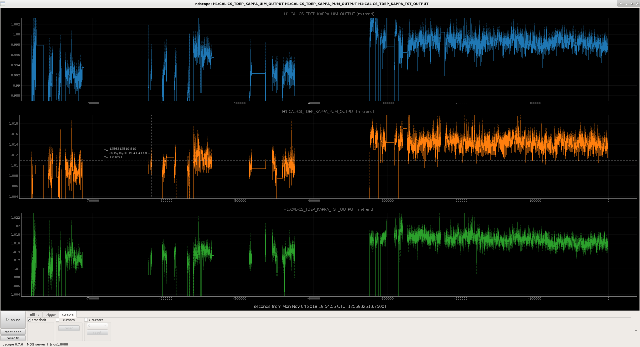
kappa via MCMC 0.986054 1.00483 1.0115
kappa via CALCS 0.995 1.0107 1.0133
So these should be close enough that we don't need to update the actuator coefficients.
Note that these will have similar 0.5% levels of systematic error that have been reported by the PCAL system in 52893 from having the wrong ETMX test mass mass. To be determined how we'll rectify this....