{Chub, Jordan, Chandra (Kyle helped as needed)}
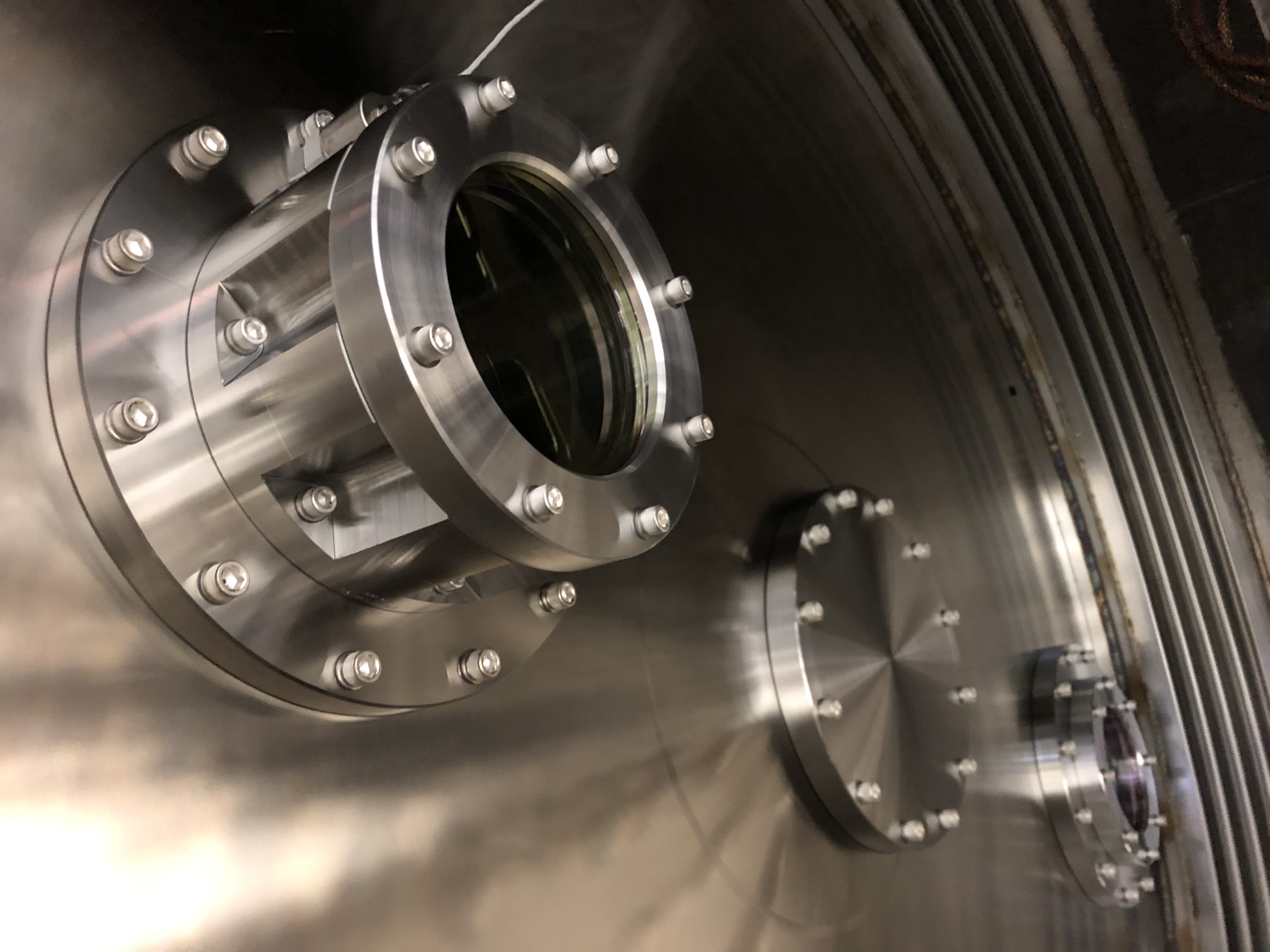
Fought the flange alignment almost all day on the new turbo installation. Was able to torque the turbo isolation GV flange when one of the 32 studs failed while approaching metal-to-metal. Tomorrow we will pull the unit back and redo flange and chase thread on GV blind hole (if needed).
YMB is being pumped by turbo since this morning. Pressure is currently 1e-6 Torr. At some point we need to move aux pump cart to GV5's annulus to hog out air from known inner o-ring leak on manifold side.
[Ethan, Niko]
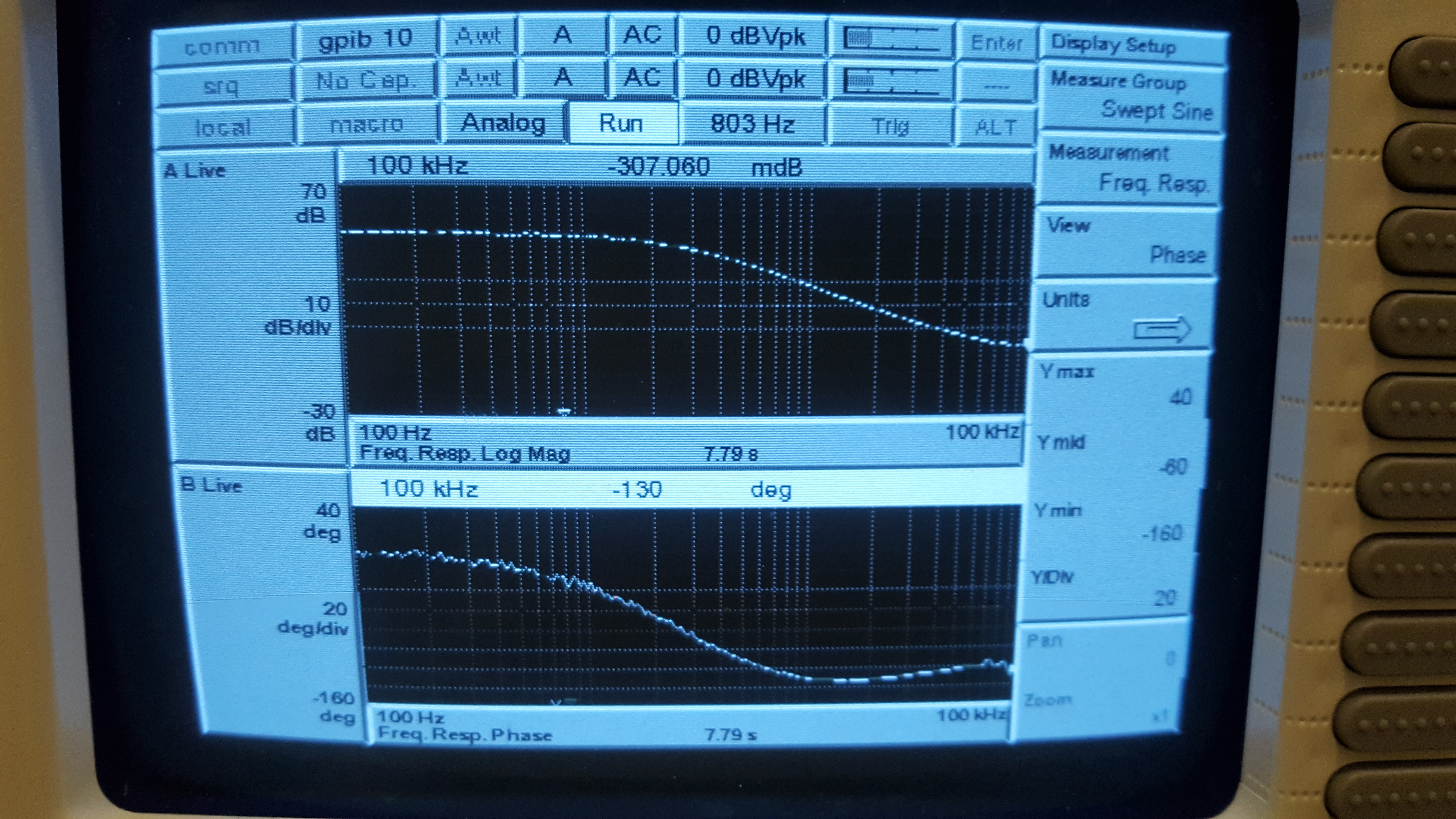
Went to EY in the afternoon for transmitter module maintenance. Tx shutter is working fine, OFS range is about where it was previously, laser output power is exactly where it was 6 months ago, and the AOM diffraction efficiency is doing well at 81.4%.
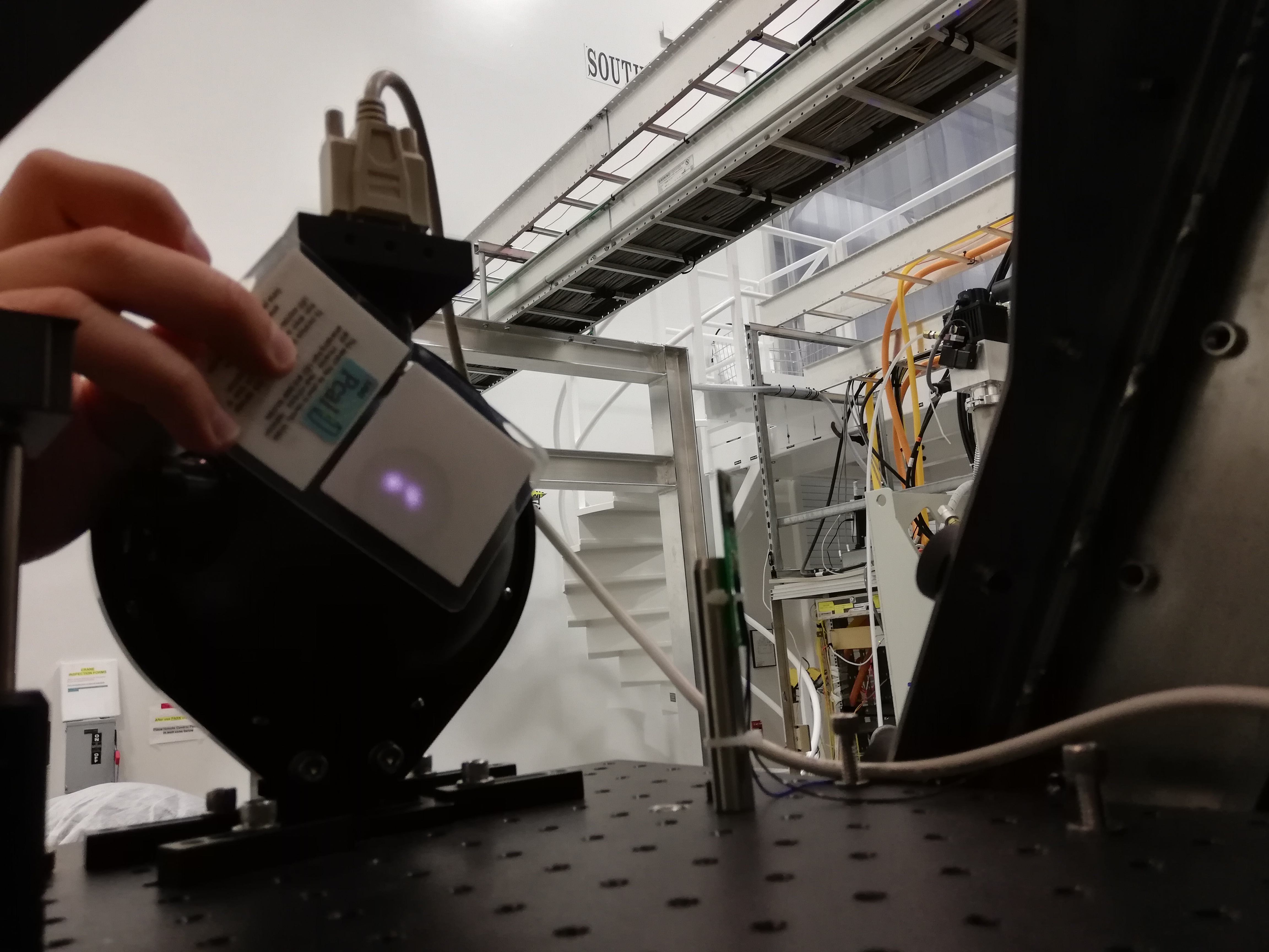
OFS Open Loop Transfer Function Bode plot attached below, along with the filled-out maintenance document. Rx beam alignment looks poor (see attached), we will likely have to adjust this in the near future.
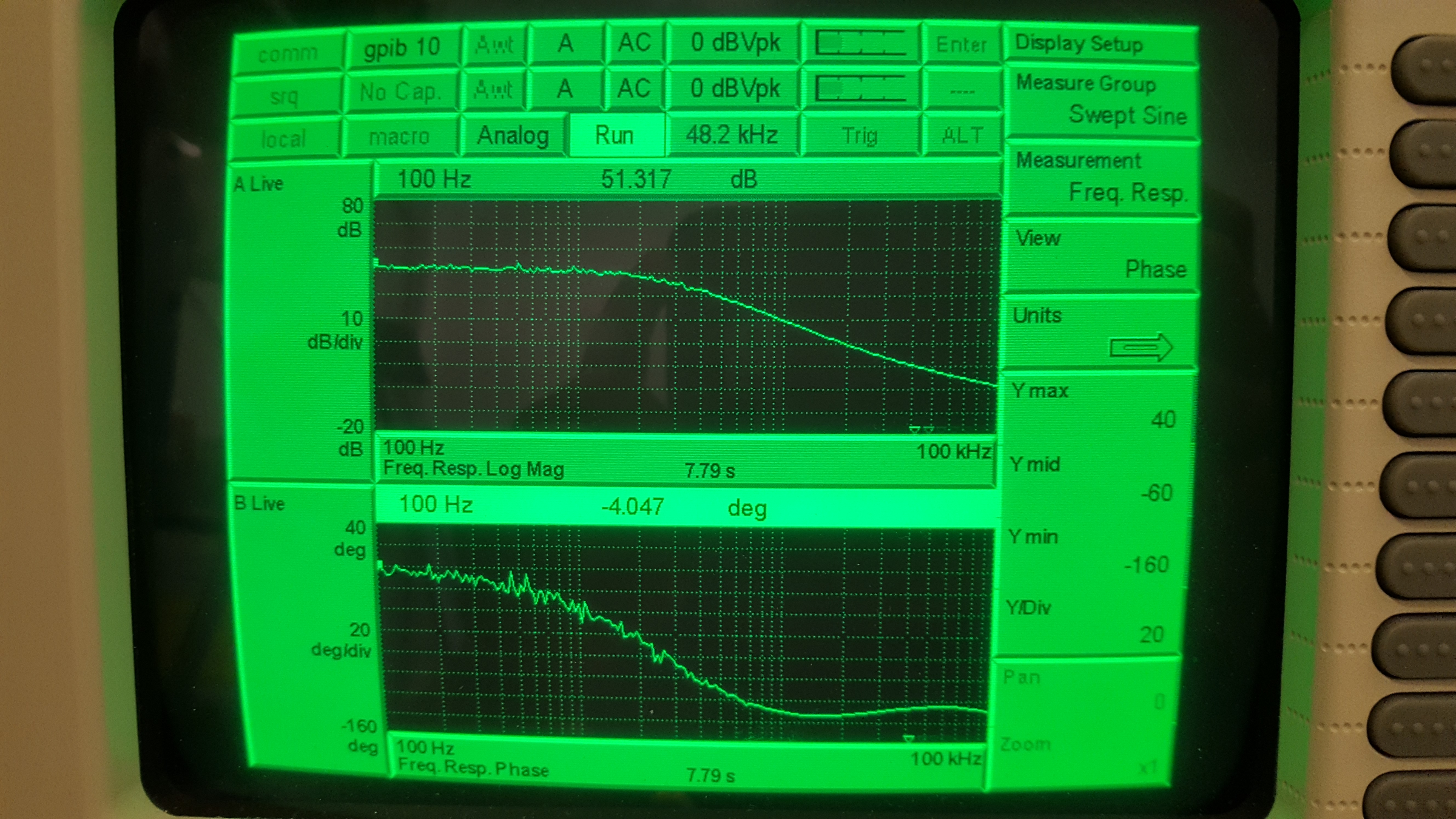
Went to EX this morning for transmitter module maintenance. Tx shutter is working fine, OFS range is about where it was previously, laser output power has dropped very slightly (1.76 -> 1.73 W over 3 months), and the AOM diffraction efficiency is at 69% (not great but not needing adjustment just yet).
OFS Open Loop Transfer Function Bode plot attached below, along with the filled-out maintenance document. Rx beam alignment looks good.
Betsy had warned that earlier this morning during the venting of the vertex, a few ISIs had tripped. She warned that perhaps they might trip again as we pump back down, and a few did.
I am recovering:
To clarify, HAM6 doors are still off. HAM5 doors were never removed. Septum window viewport assembly was swapped and the corner (minus HAM6) is now in the vacuum teams hands for pump down.
From about 21:15 to 22:30UTC (2:15 to 3:30 PM Local) I had the fan running on ISCT1, and doors open (one at a time) to verify the current version of the DCC layout for H1 ISCT1. Mostly the layout was correct. I found one additional lens, one iris, and some beam dumps that are moved. No changes.
C. Gray, G. Moreno, T. Sadecki, B. Weaver
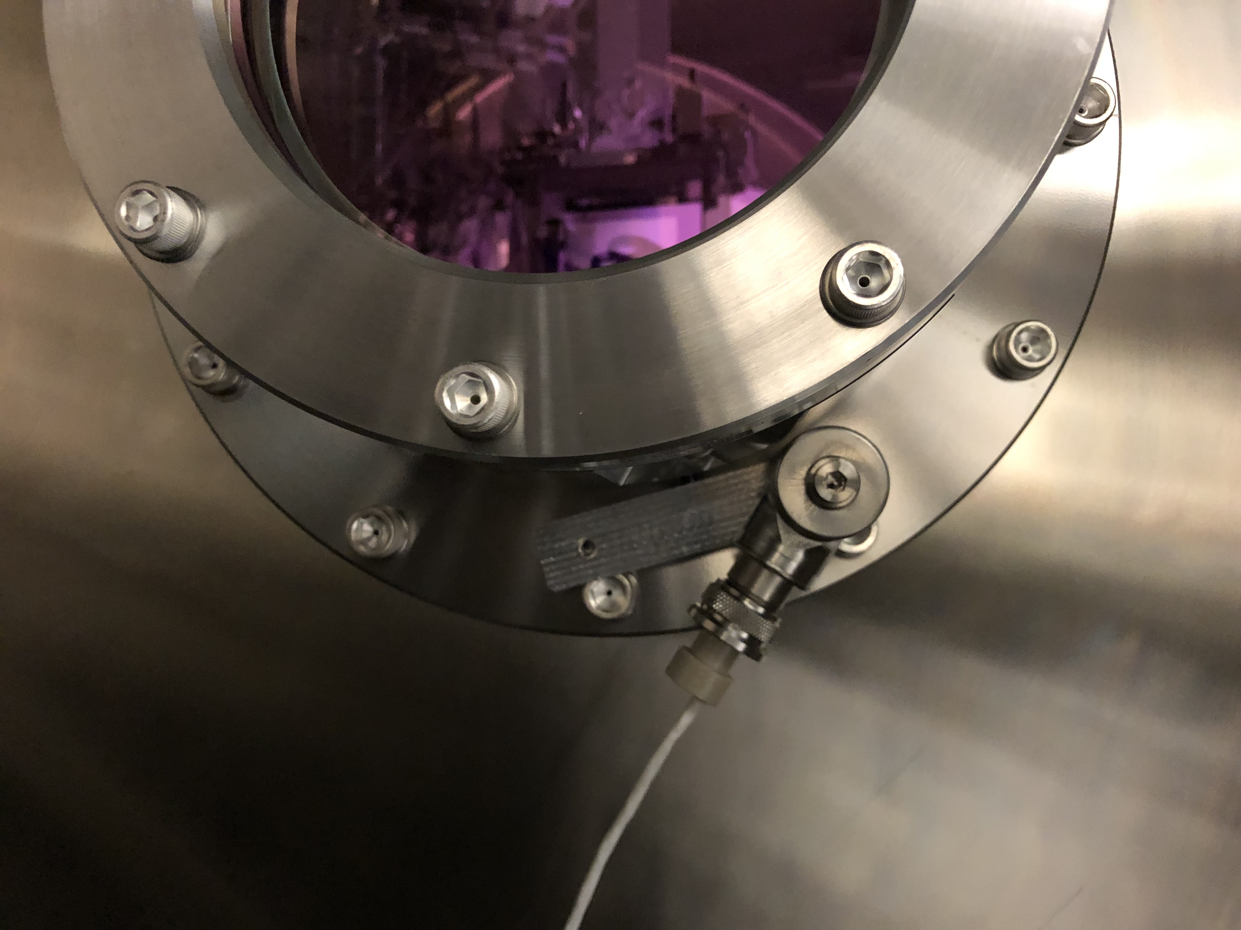
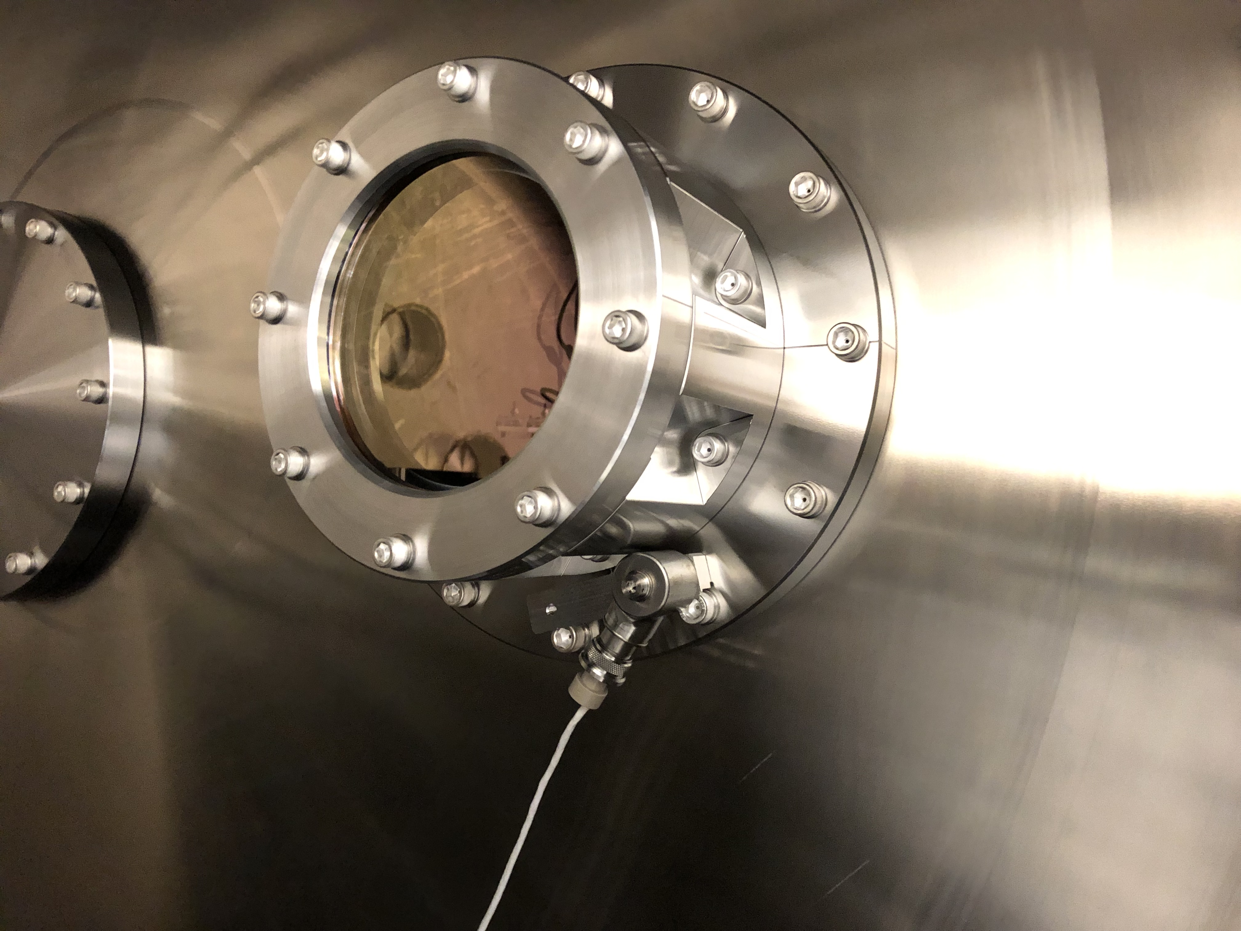
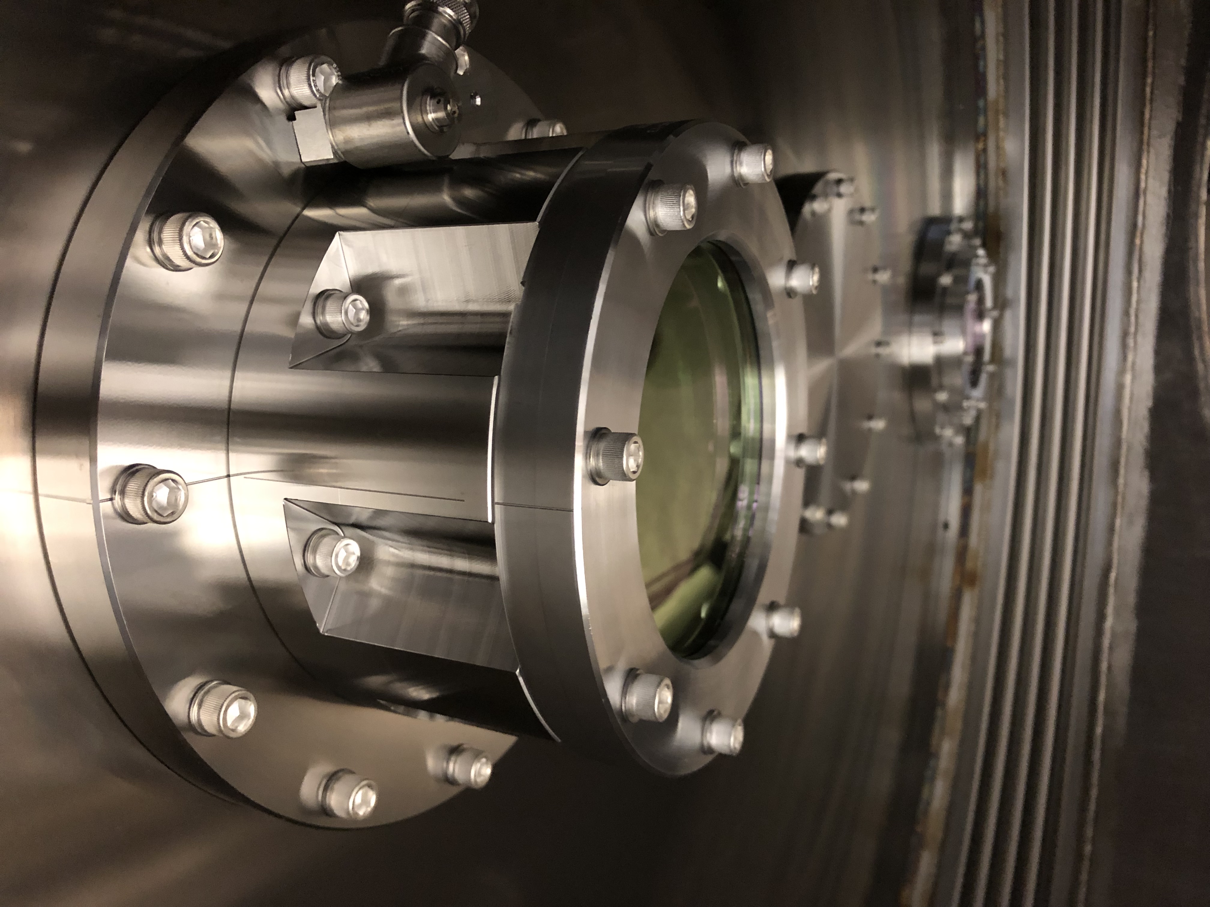
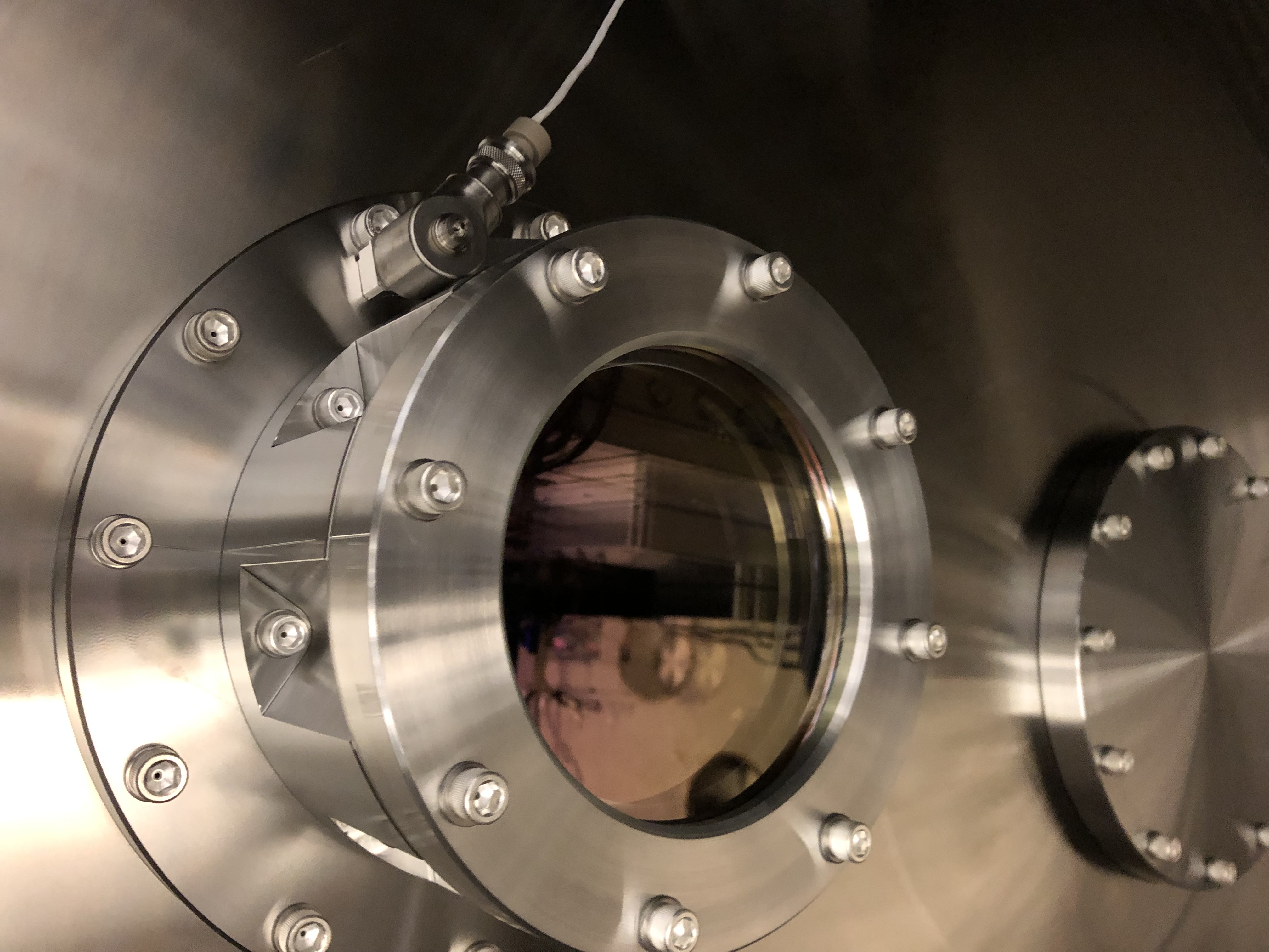
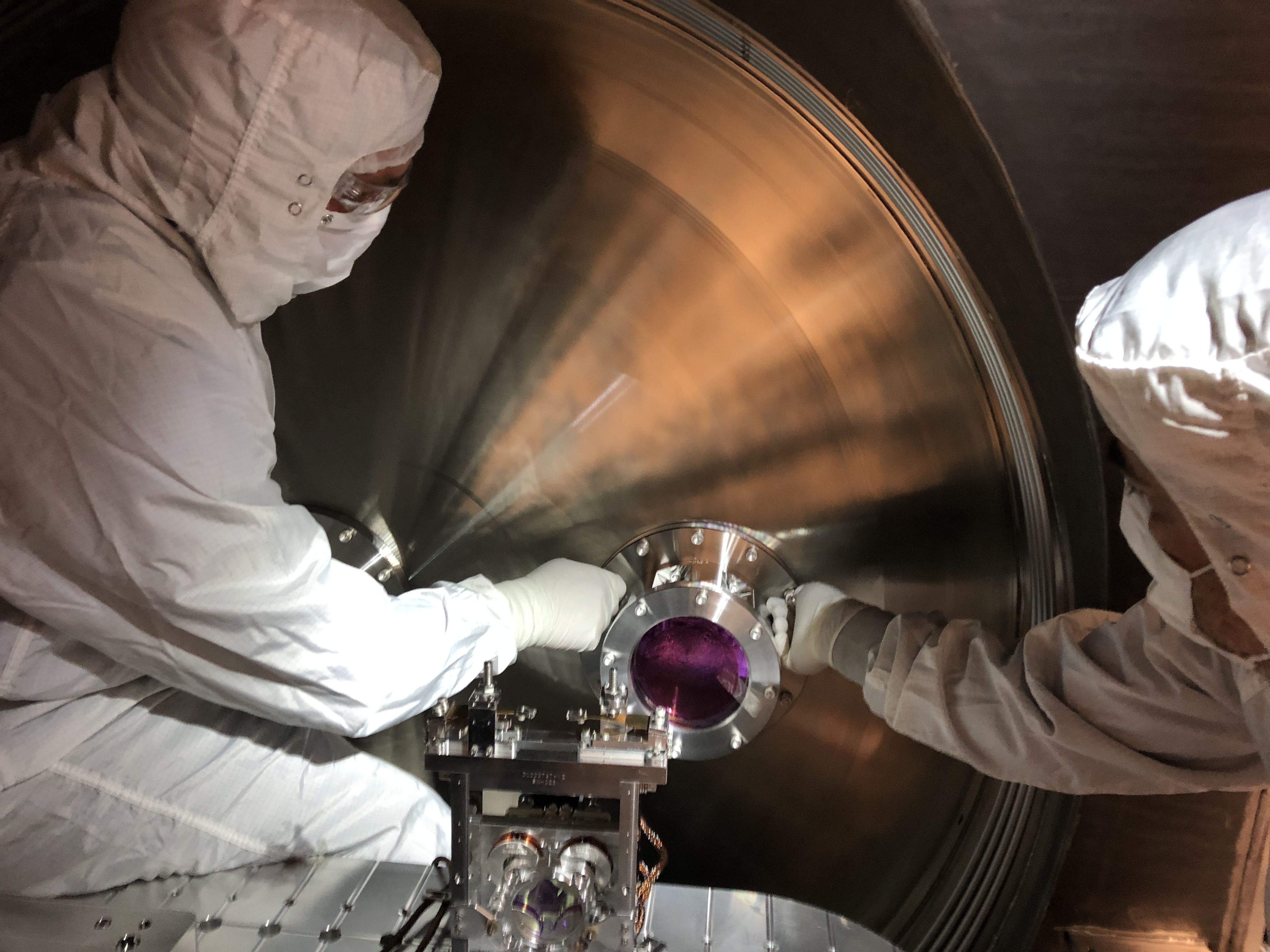
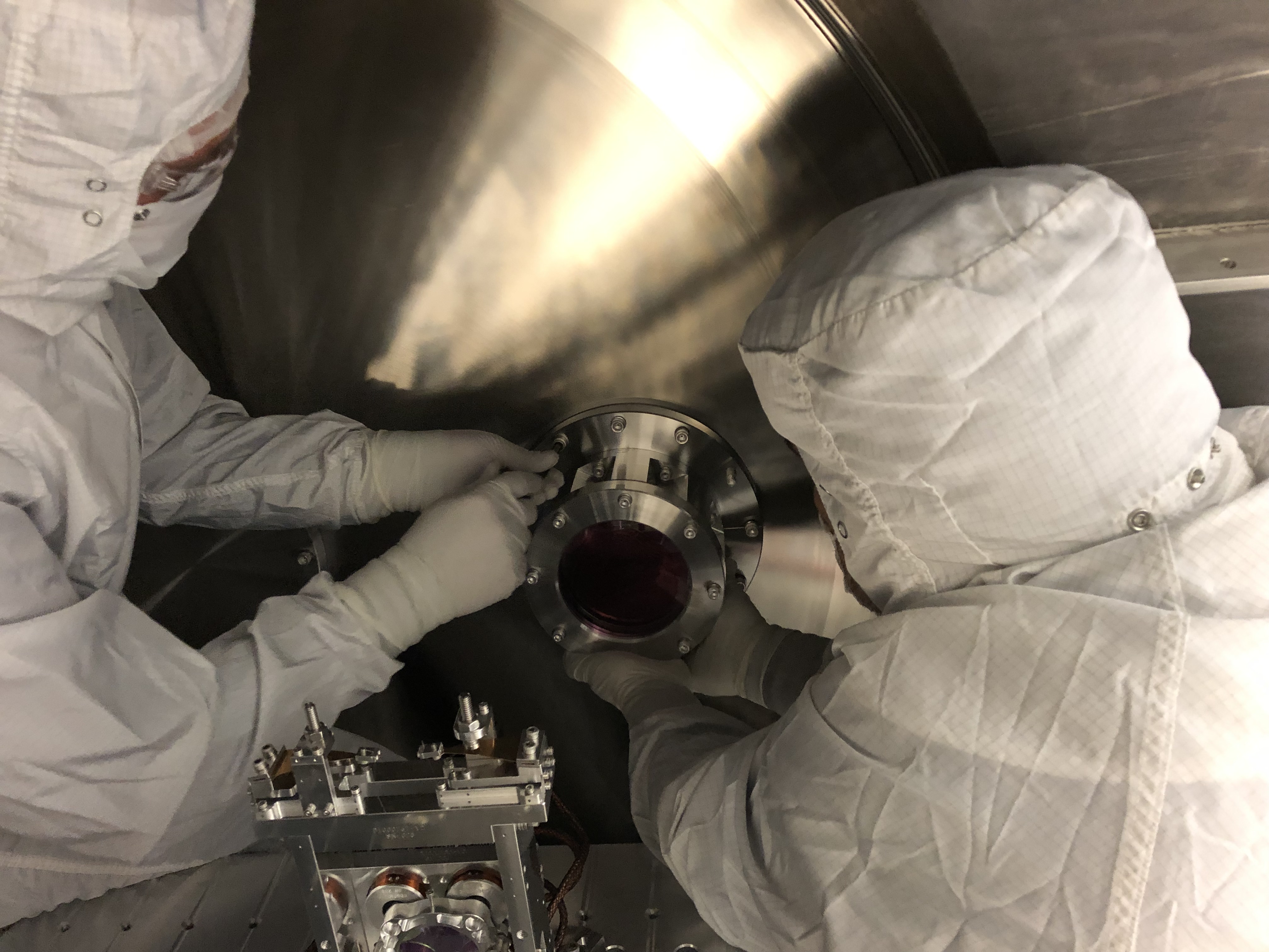
Install of the new yawed septum viewport in HAM 6 went very smoothly today. We utilized 2 of the aligment pins (3/8-16 silver plated screws with the heads lathed down to thread diameter) that Tyler made for us. This made the installation much easier as we had something to take the weight of the 22 kg viewport assembly while installing the mounting flange screws. The septum window accelerometer was reinstalled in the same location it was removed from. First Contact was removed from the inner, HAM 5 side prior to installation, and the outer, HAM 6 side was removed in-chamber after installation and torquing. The center of the viewport aperture was inspected and was deemed free from egregious amounts of particles.
On a related note, this was the first time I had the chance to use the new modular stair system around the HEPIs and can attest that they work much better than the previous iterations of HAM chamber stairs.
Photos to follow.
Attached are photos from new yaw-ed septum viewport install at HAM6 (names of pics gives brief description of image).
Is it in somebody's to-do list to add a notion of the alignment pin fixturing to the documentation? Seems like that fixture should be part of the final drawing package. Let me know if a hand is needed with that.
The "alignment" pins were a last minute tool made to help support the weight of this ~ 50 lb piece of hardware. A design improvement would be to reduce the weight by perhaps making it out of aluminum. It is difficult to get two bodies in the chamber for this maneuver and diverted the time of one of our vacuum engineers a full day.
For the record, this is the AS viewport assembly that was removed:
| ASSY-D1101092-3 | HQ Wedged 6 in Septum VP | |
| 2-253V75--BULK-C30Q002 | Dupont O-Ring #AS568-253 Viton 75, V75 FKM, Inside Diameter 5.359", Cross Section 0.139" | |
| D1003207-V1-00-C6Q002 | High quality, 6in Viewport, Viewport Spacer | |
| D1101005-V1-12KWZ-S5-1363-S5-1364-0015 | aLIGO, high quality, .75 deg wedged, 6" Viewport, AR-1064 nm Optic | |
| D1101115-V5-00-0007 | High Quality, 6" Viewport CLAMP, wedged | |
| D1101117-V3-00-0006 | aLIGO Septum Viewport FLANGE |
And this is the viewport assembly that was installed earlier this week:
| ASSY-D1900198-001 | LHO Yawed, Septum Viewport Assy | |
| D070082-V1-00-0006 | ELI Septum Window | |
| D1101117-V3-00-0022 | aLIGO, Septum Viewport Flange | |
| D1900240-V3-00-0001 | aLIGO, VE, HIGH QUALITY VP, WEDGE CLAMP | |
| D1900327-V1-00-0002 | aLIGO, VE, HIGH QUALITY VP ASSY., YAW ADAPTER |
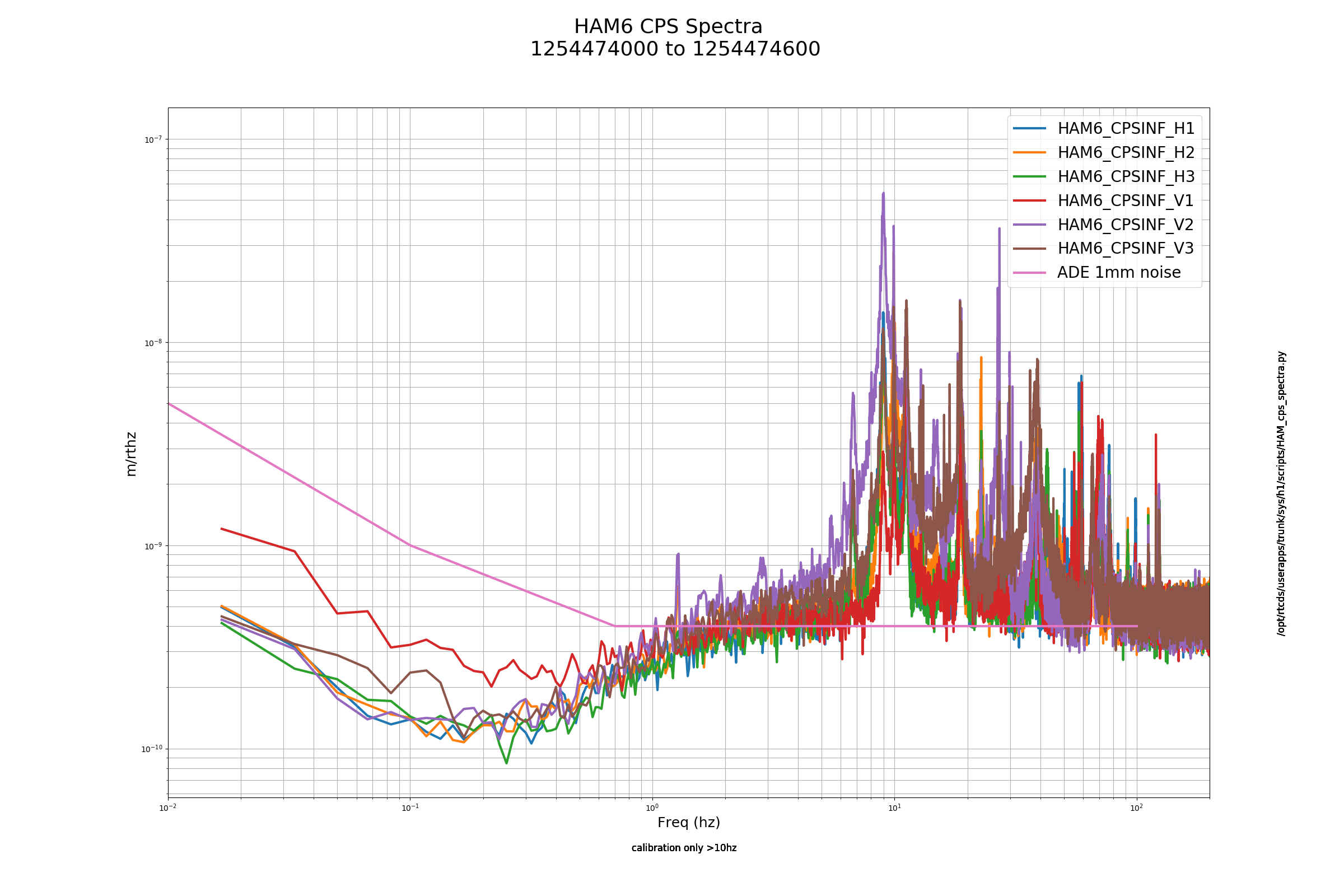
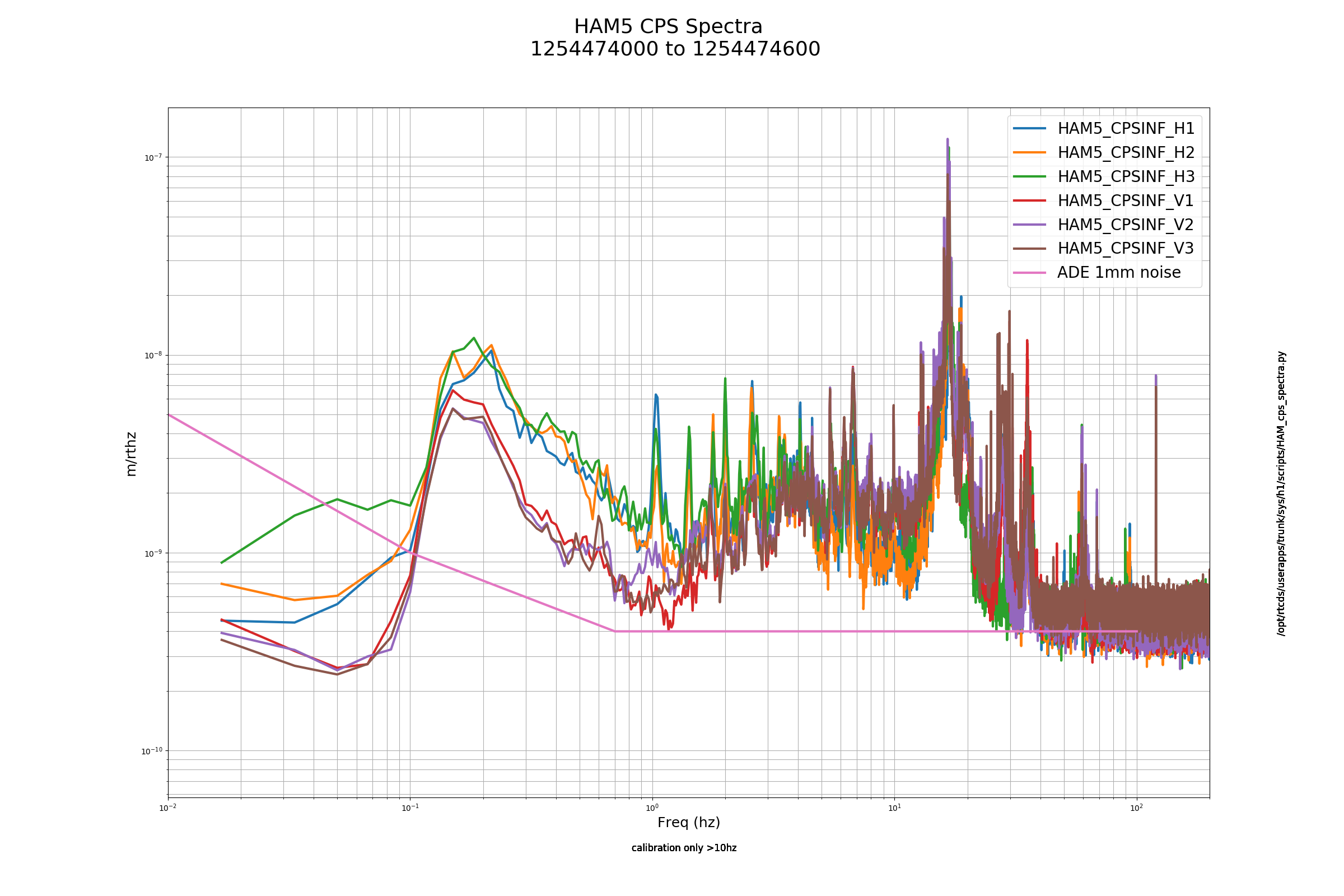
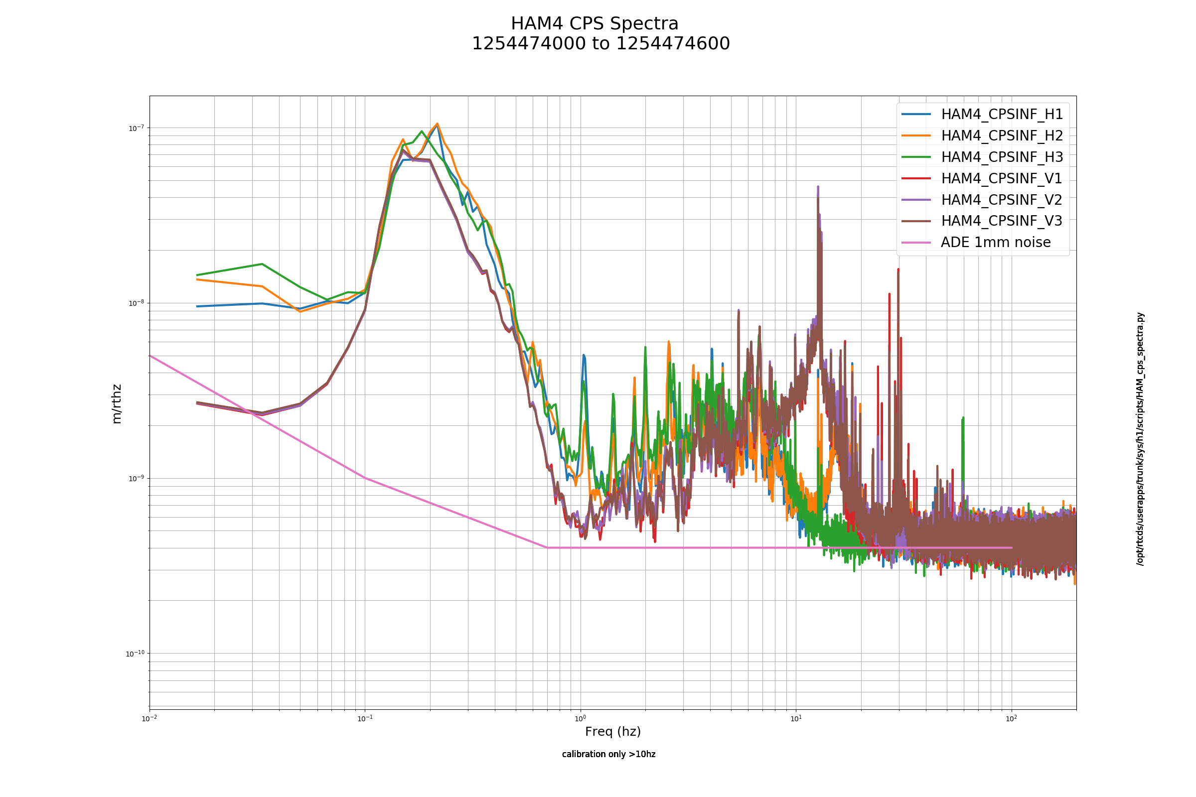
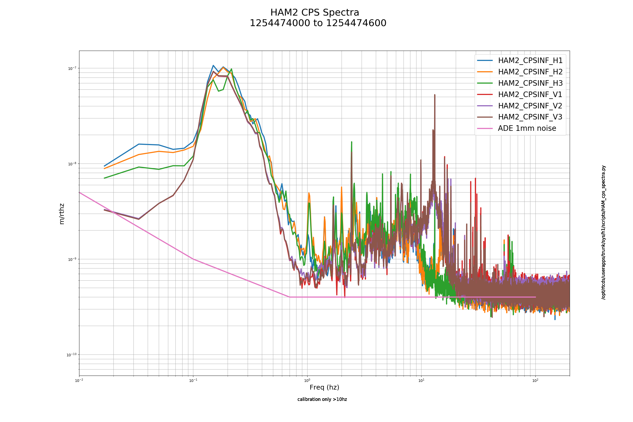
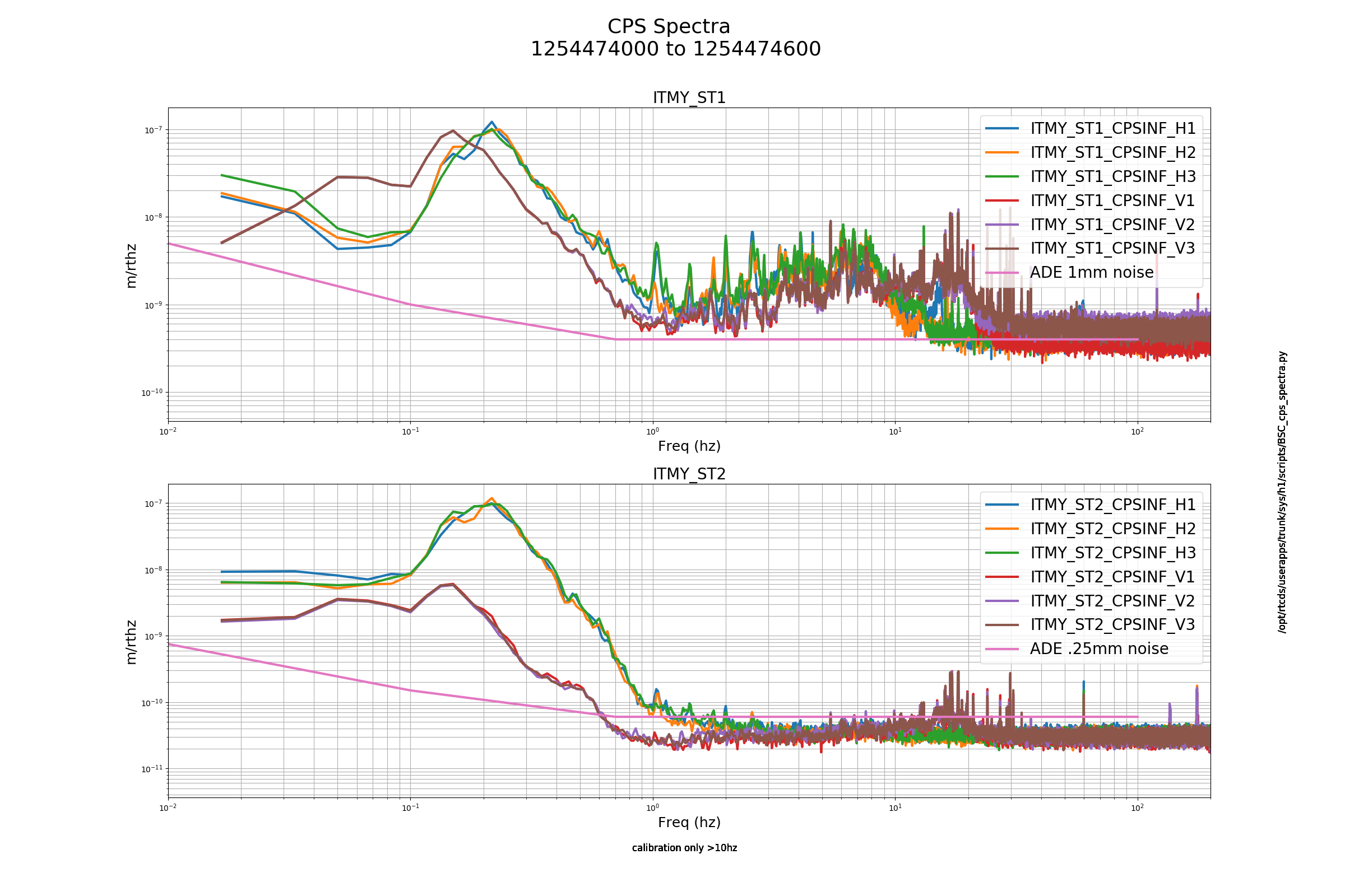
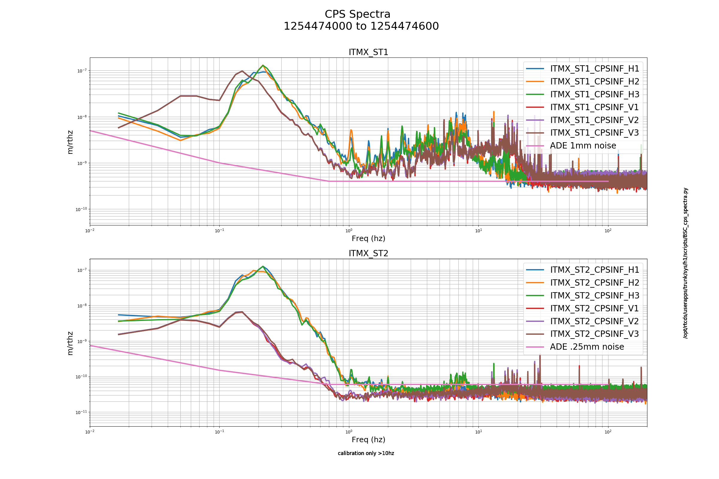
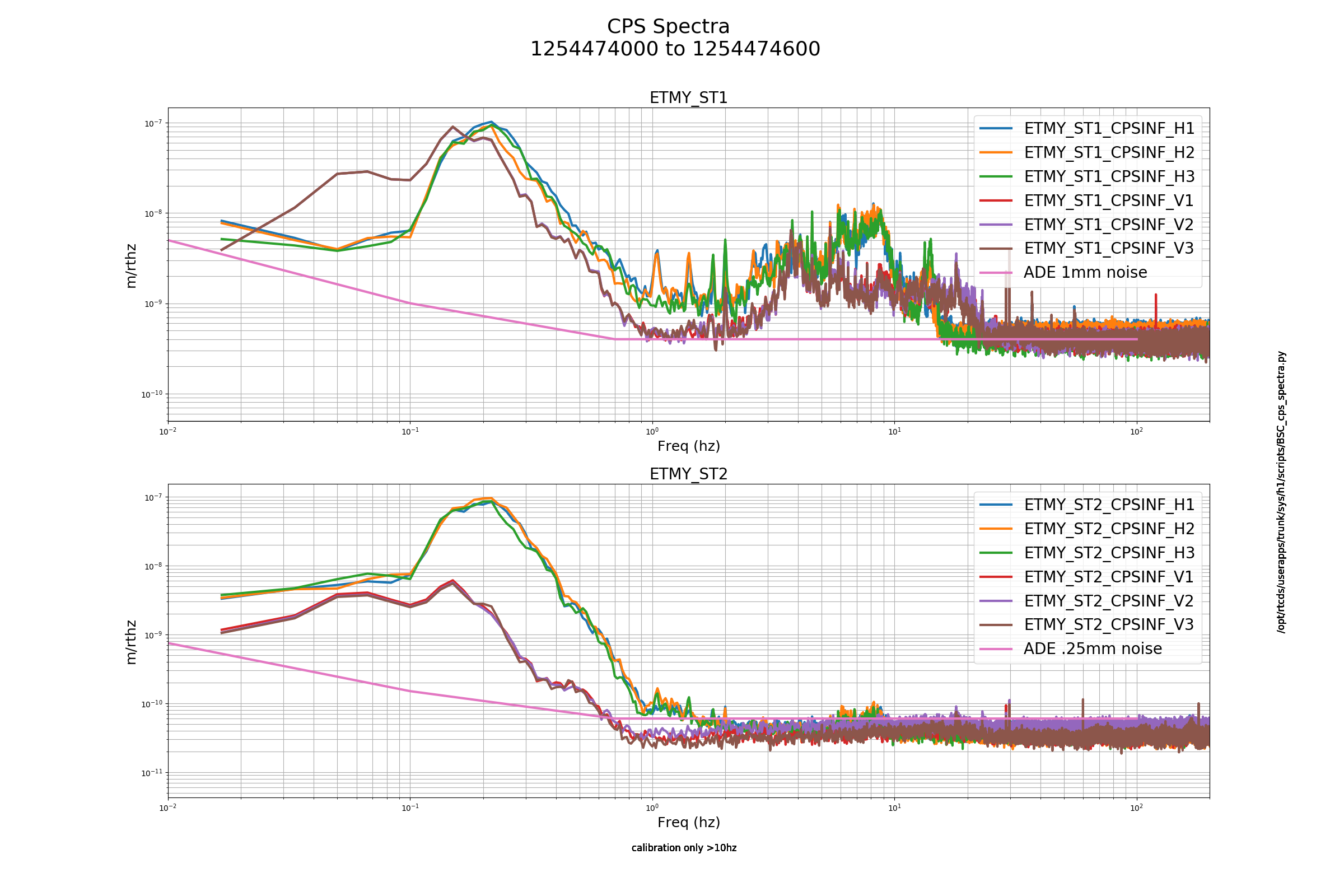
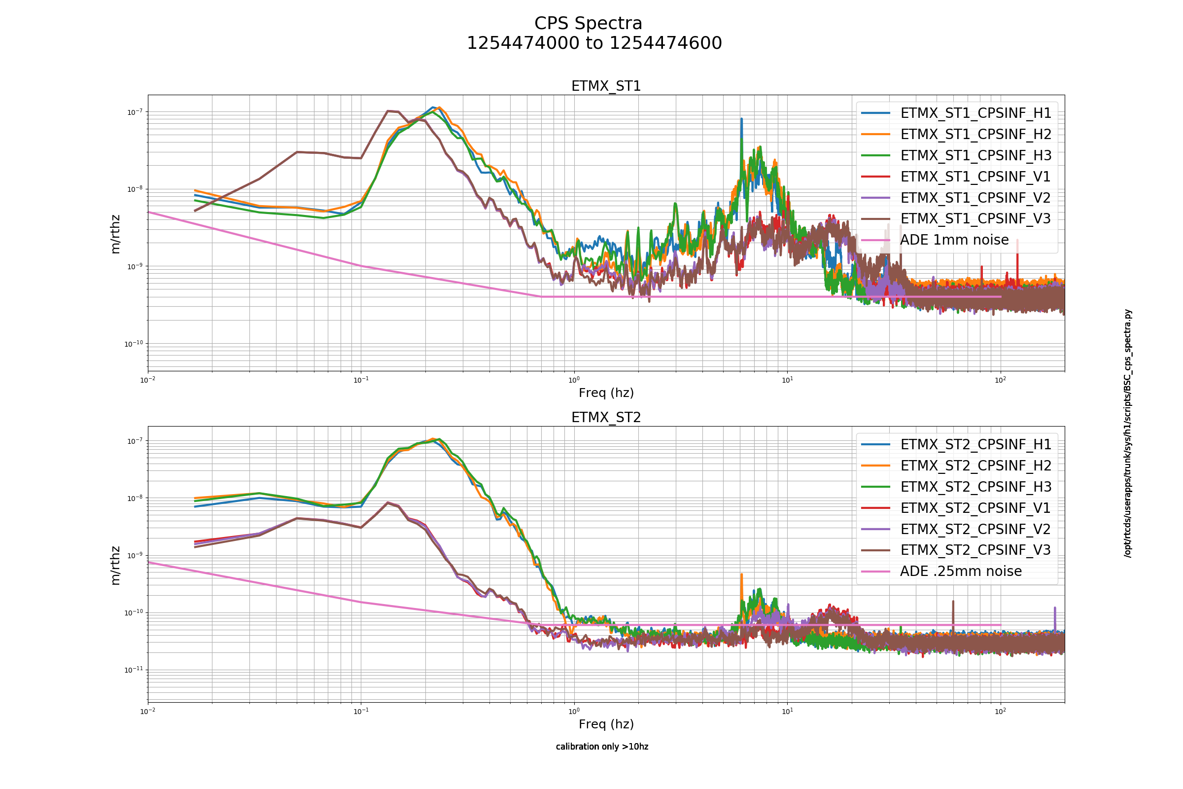
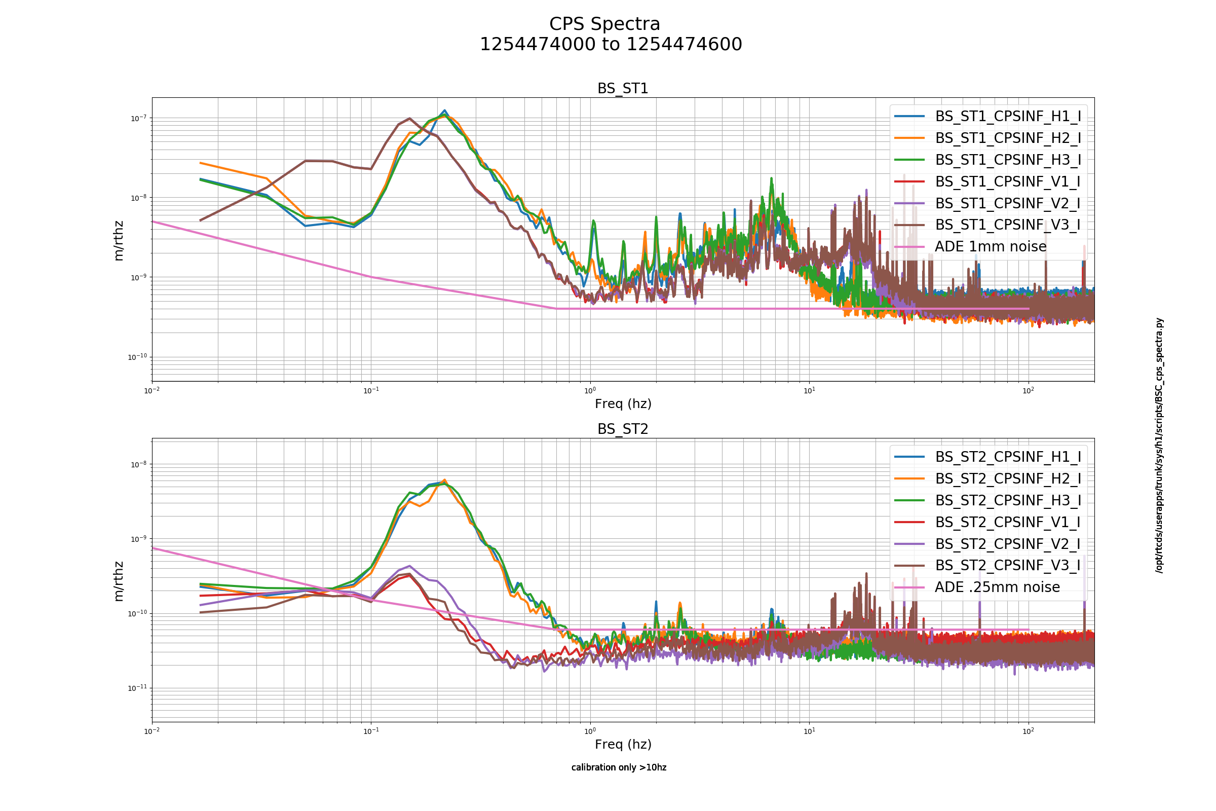
Posted are the CPS Noise Spectra Checks. The IFO is down for planned engineering.
Closing FAMIS # 12868
Laser Status:
Front End Power is 32.57W (should be around 30 W)
70W Output Power is 69.02W
Front End Watch is GREEN
70W Watch is GREEN
PMC:
It has been locked 12 days, 23 hr 57 minutes (should be days/weeks)
Reflected power = 12.13Watts
Transmitted power = 51.91Watts
PowerSum = 64.04Watts.
FSS:
It has been locked for 3 days 2 hr and 59 min (should be days/weeks)
TPD[V] = 3.049V (min 0.9V)
ISS:
The diffracted power is around 2.9%
Last saturation event was 0 days 0 hours and 0 minutes ago (should be days/weeks)
Possible Issues: No issues to report. Site is in Planned Engineering for vent.
Daniel, Dave:
Daniel made a h1sqz model change to add four new ISS filtermodules ( CTRL and ERR for CLF and OPO). He also made the corresponding change to the Beckhoff C1PLC4.
Between the times of 12:24 and 12:35 PDT I restarted the following:
h1sqz model
DAQ, followed quicked by h1edc
Note that h1nds3 (stand-alone EDCU) was not restarted. This system does not have the new PLC4 slow channels.
I took the opportunity to restart a stuck Slow-Controls SDF system (h1sysecatc1plc1sdf).
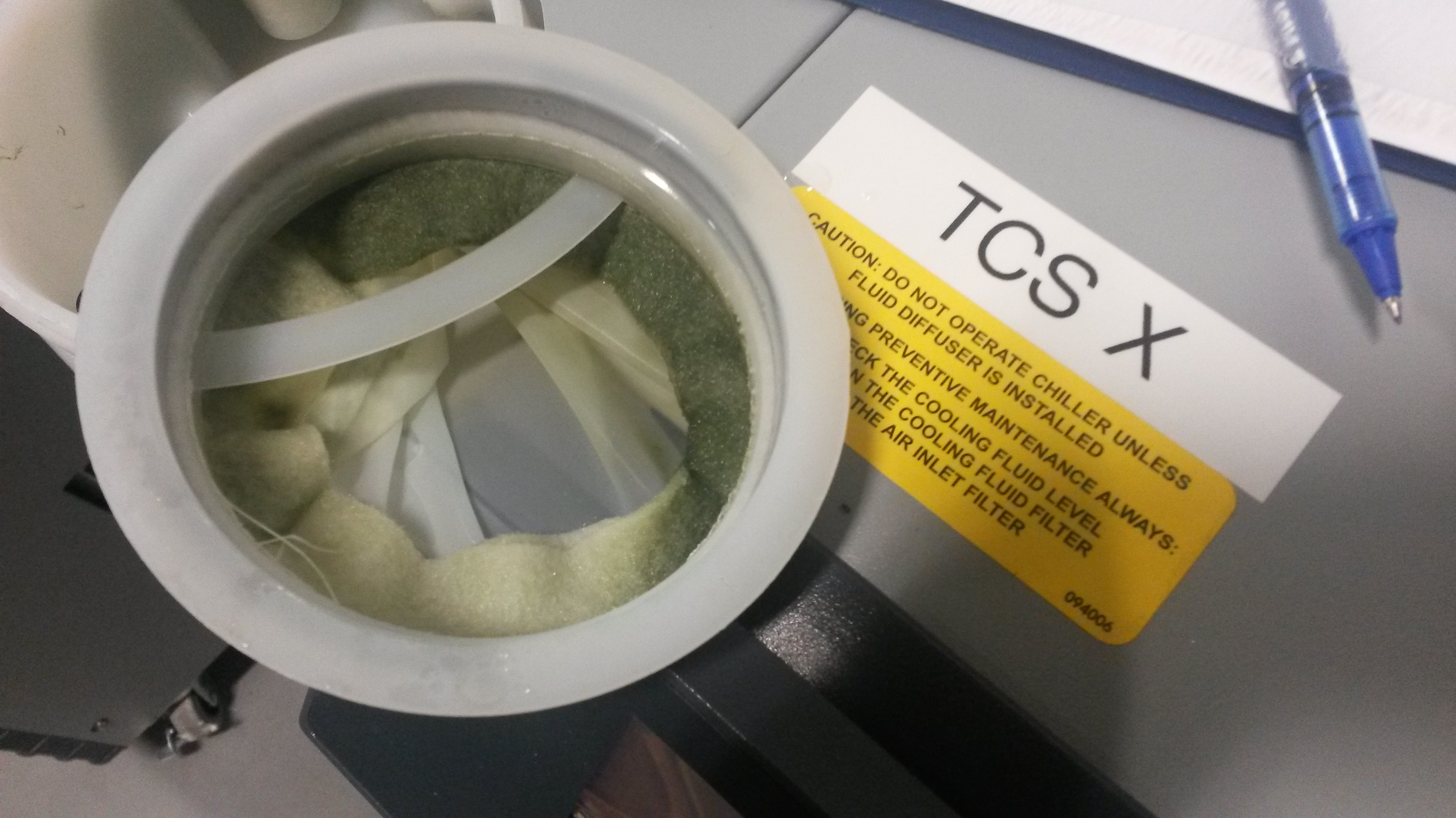
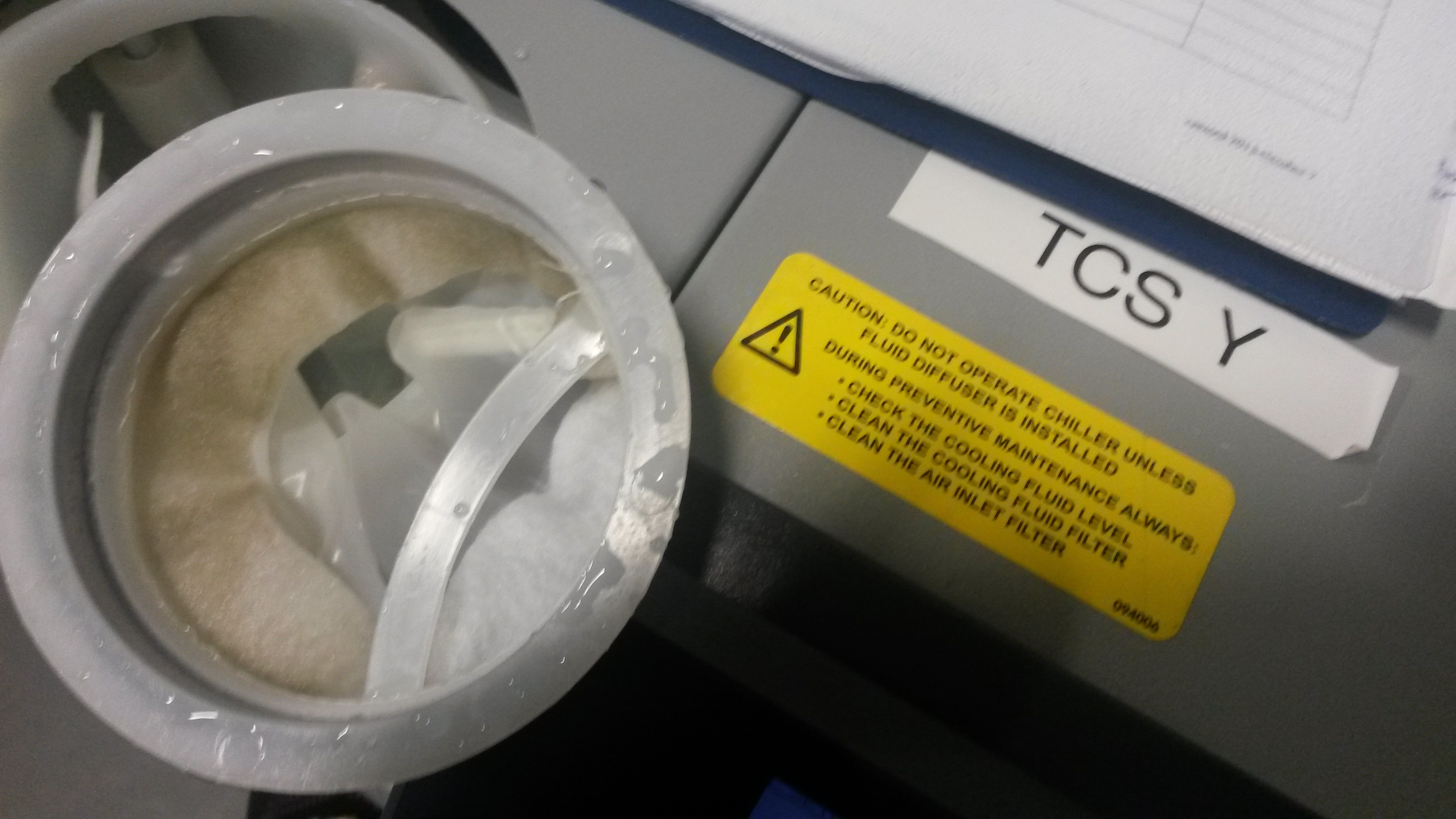
added 350ml toTCSX, 700ml to TCSY.
The TCSX filter is quite green, and when I popped the filter out, I saw a green line of resudue on the tank under the area where the filter seals to the tank. This was most obvious where the return water emptys into the filter. The green resudue easily wiped off. The TCSY chiller, in contrast, was not green at all, and there was no evidence of any resudue under the filter.
This is a follow up on measurements done in 51546 and modeling 50610 A few weeks ago I did a longer set of squeezing measurements using the full range of the CLF demod phase shifter and the sign flip in the CLF servo board. I repeated the measurement for the nominal 100 count SRCL offset which we use to minimize the optical spring, and an offset of -100, which corresponds to roughly a 100 to 120 nm detunign of the SRC (extrapolating from 51592). The first attachment shows these measurements with the correlated noise subtracted, you can see that we are reaching nearly .
The second and 3rd attachments shows the same data, I've taken the median in several frequency bands (avoiding lines) for each demod phase and used an MCMC fit for a model that includes loss, nonlinear gain, phase noise, and the ratio of the OMC 3MHz semi-major and semi-minor axsis. I used Daniel's expression here to model the realtionship between squeezing angle and demod phase. The last attachment is a collection of the corner plots for all of these fits.
The next two plots show the fit parmeters plotted as a function of frequency for the nominal SRCL offset and with SRC detuning. In these plots the blue stars show the median of the posterior dsitribution, while the triangles show the 16th and 84th percentile of the parmeter. I've divided out the budgeted effecincy based on the known losses so that we should be able to compare these plots to similar plots produced by Lee's code. I've plotted the normalized nonlinear interaction strength x, which is not frqeuency dependent, because there is some frequency dependence in the fit results, because of degeneracy with phase noise.
The code used to make these plots is available here, inlcuding a script which will run the measurement by slowly varying the CLF demod phase and SRCL offset, and sqz_as_phase_rotates,py, the main script which produces the plots.
Here are the fit parameters again, this time the total efficicnecy is plotted (with no dividing out of known losses). In the plots above, I subtracted the squeezing angle offset for the lowest frequency band (labeled ang1) from the other points so that the squeezing angle rotation is shown. Lee points out that the shift in the angle between the different SRCL offsets is also interesting so I have not subtracted from these attached plots.
Also attached is the fit of the LO error signal in the Q phase as the CLF demod phase is rotated, similar to what was done in 51546 The magnitude and ellipticty of the LO Q signal didn't change when the SRCL offset changed, but the axis was shifted by -10.7 degrees for the detuned SRC.
Needed some internet so I'm here to monitor YBM pump down while catching up on personal volunteer work. Will valve QDP80 back out and log when I leave.
QDP80 is valved back out. Pressure fell to 180 mTorr. Will be ready for turbo first thing Monday morning. I'm leaving the site.