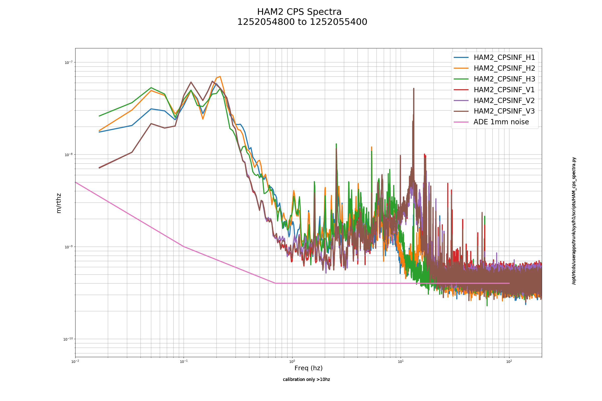
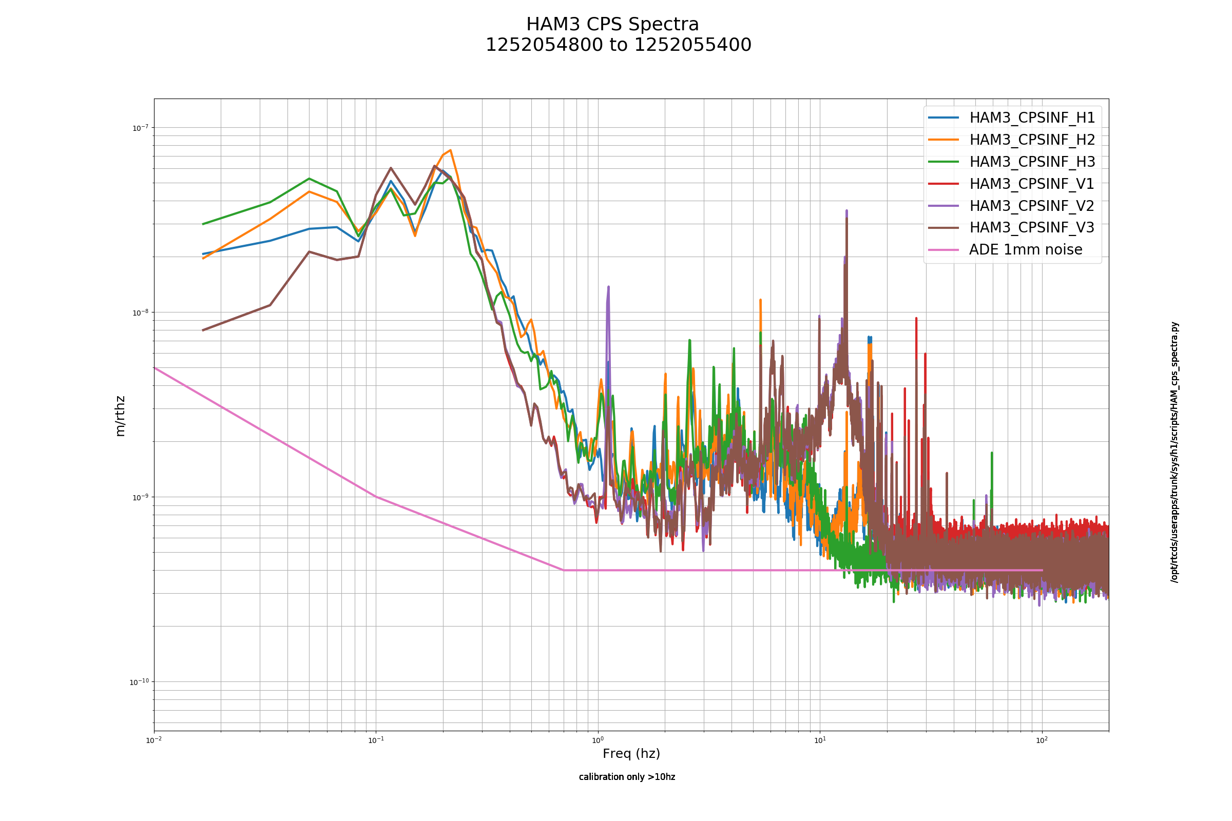
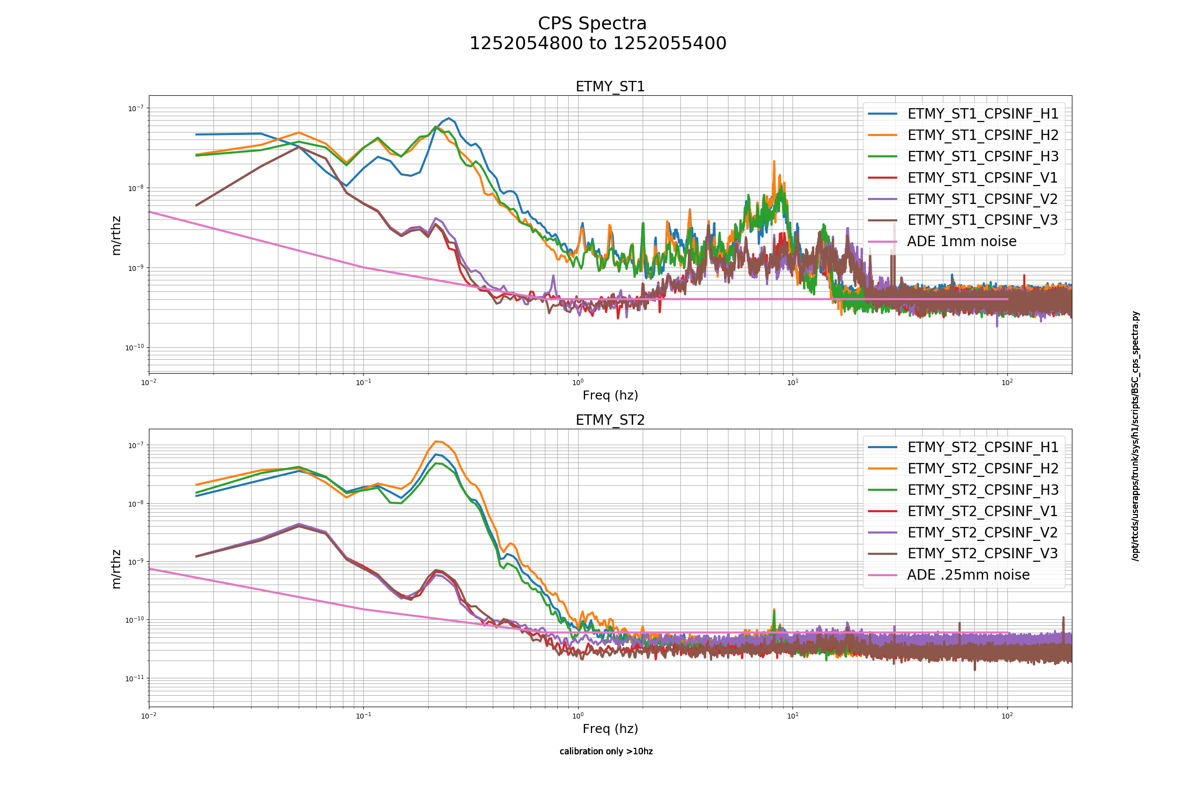
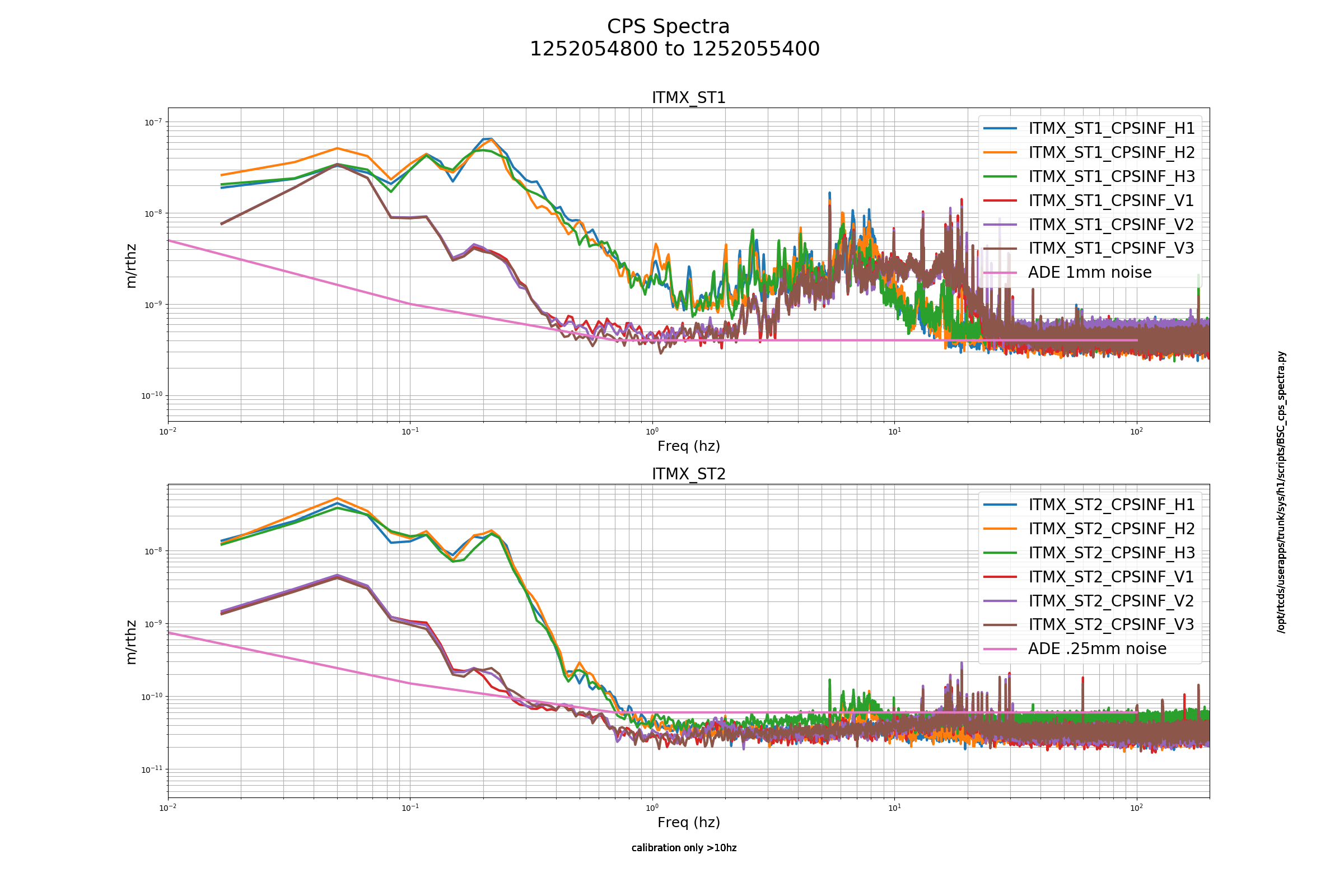
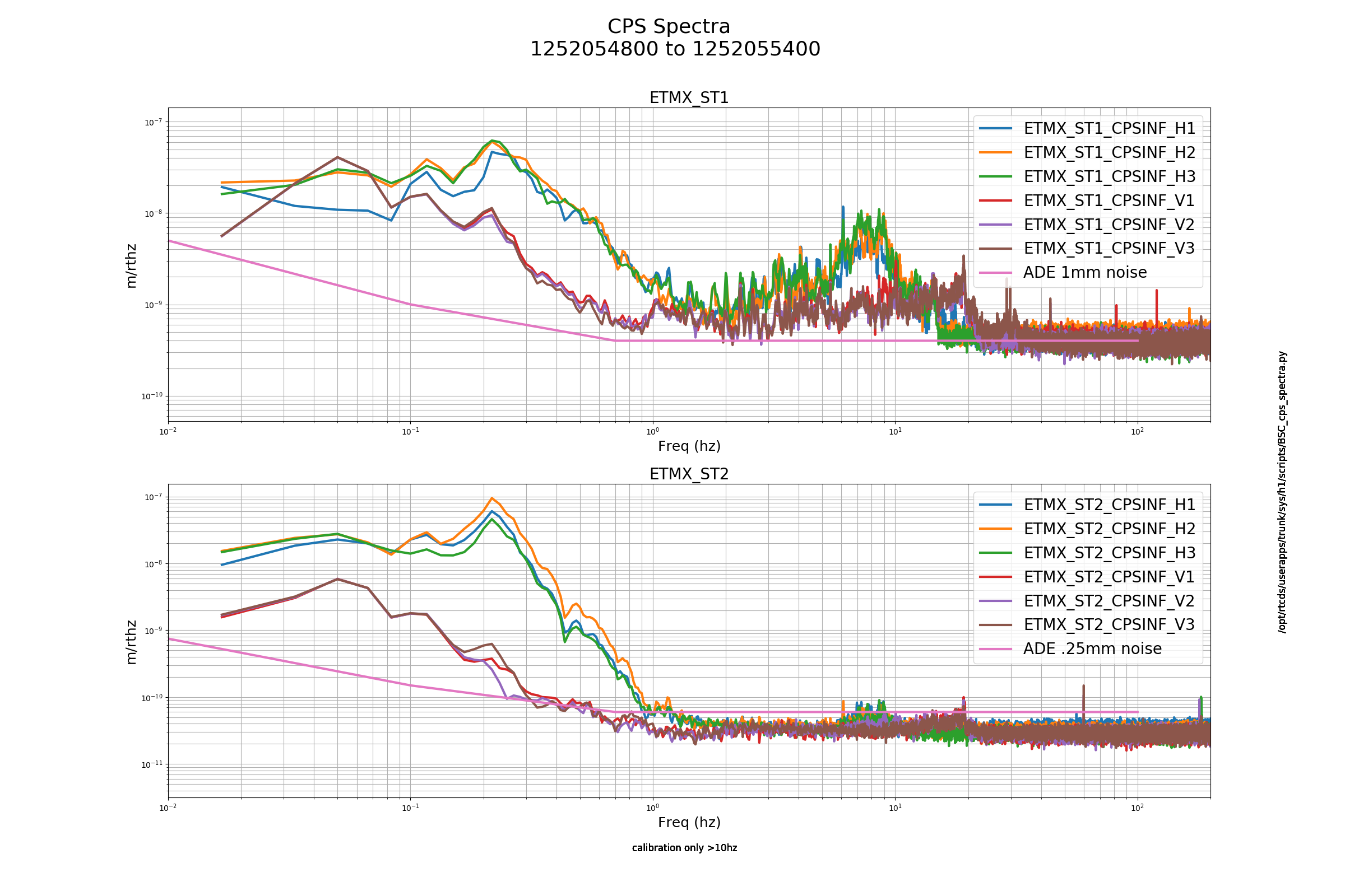
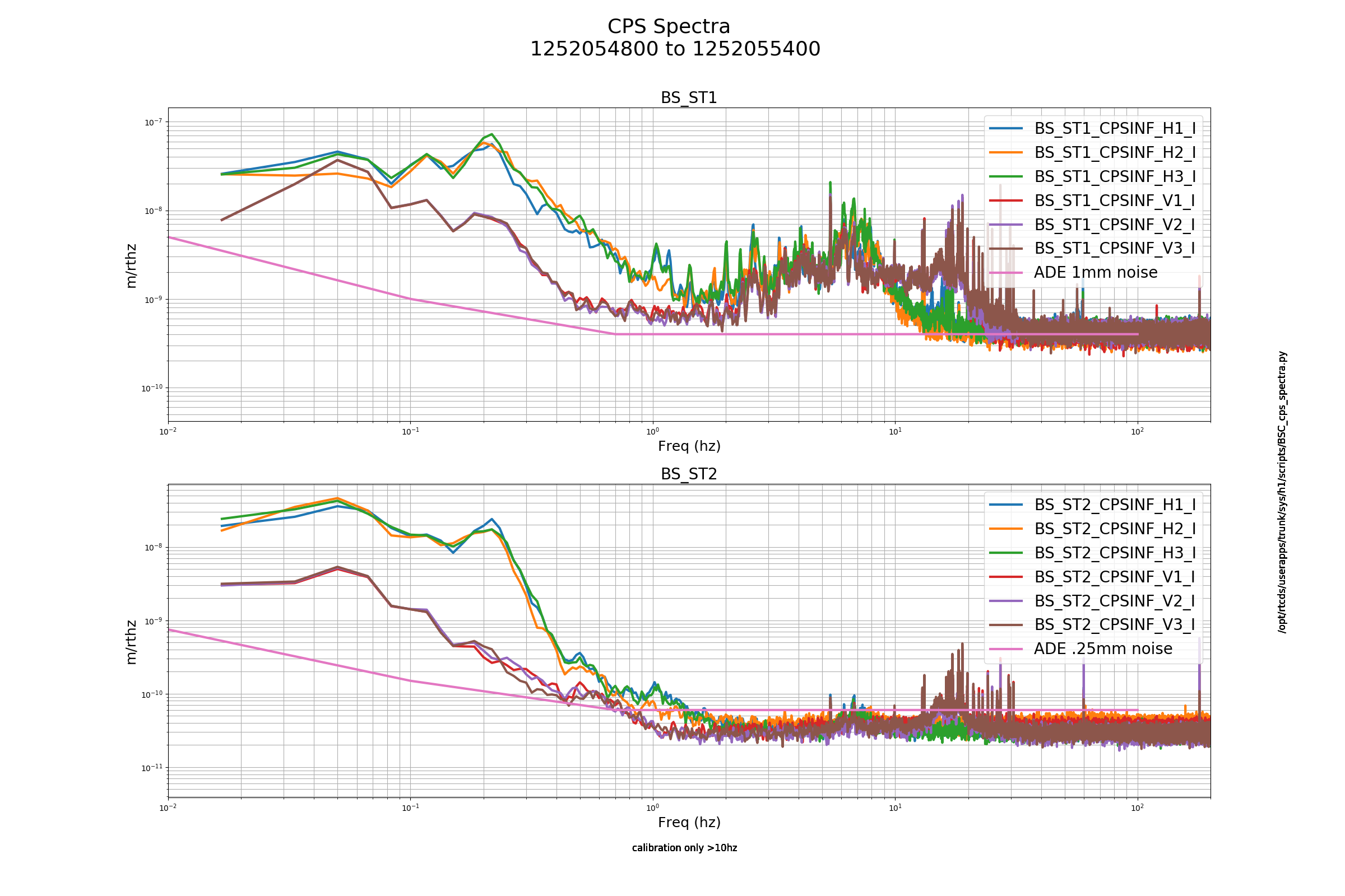
All three HEPI pump stations (End-X, End-Y, CS) fluid levels were good. There was no change from 09/03 check. There may be a new leak under the pump/motor end of CS HEPI pump station #4. Put an absorbent pad under it and will monitor.
TITLE: 09/10 Owl Shift: 07:00-15:00 UTC (00:00-08:00 PST), all times posted in UTC
STATE of H1: NOMINAL LOW NOISE but out of OBSERVING for Maintenance
INCOMING OPERATOR: Ed
SHIFT SUMMARY:
LOG:
Now that we are back to Observing, figured I'd post locking notes from the night.
Summary:
Locking Notes:
J. Kissel
Regarding Corey's comment:
NOTE: getting "IMC WFS not centered" messages for IMC LOCK. Observe this in all the space it takes up in the ISC LOCK log.
This is a known issue/problem that is not resolvable without a hardware change: check out my aLOG from tail end of July: LHO aLOG 50920, and Daniel's subsequent reference to 5109.
To quote my aLOG: "This message appears, typically, after PSL incursions (rare), site power outages (rare), or computer failures (rare) when the IMC suspensions's or PSL Periscope PT alignments get lost. Because these events are rare, instituional memory loss causes confusion for folks when they see that error message and wonder if action is needed. However, once these alignments are roughly recovered (via reseting sliders on suspensions), the WFS, again typically, eventually recover their centering all on their own as the RF loops converge [there are no "DC centering" loops on IMC WFS, as there are for many of the the WFS systems]."
However, last night, none of these things happen, and the IM alignment is all down stream of the IMC WFS. So I'm equally confused as to why the WFS got outside of their range. Worth trending.
But in short -- while these warnings are annoying -- they are reflecting of a real issue, so don't ignore them.
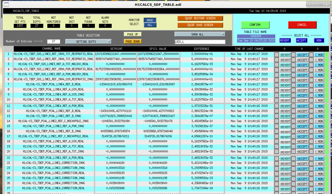
CAL CS differences are due to poor rounding of the installation of Calibration Model Reference Values art Calibration Line frequencies. Will work on resolving this later today.
Today we did have the problems with TR_CARM that Corey and Niko descirbed last night, and we think we have addressed the problem: 51861
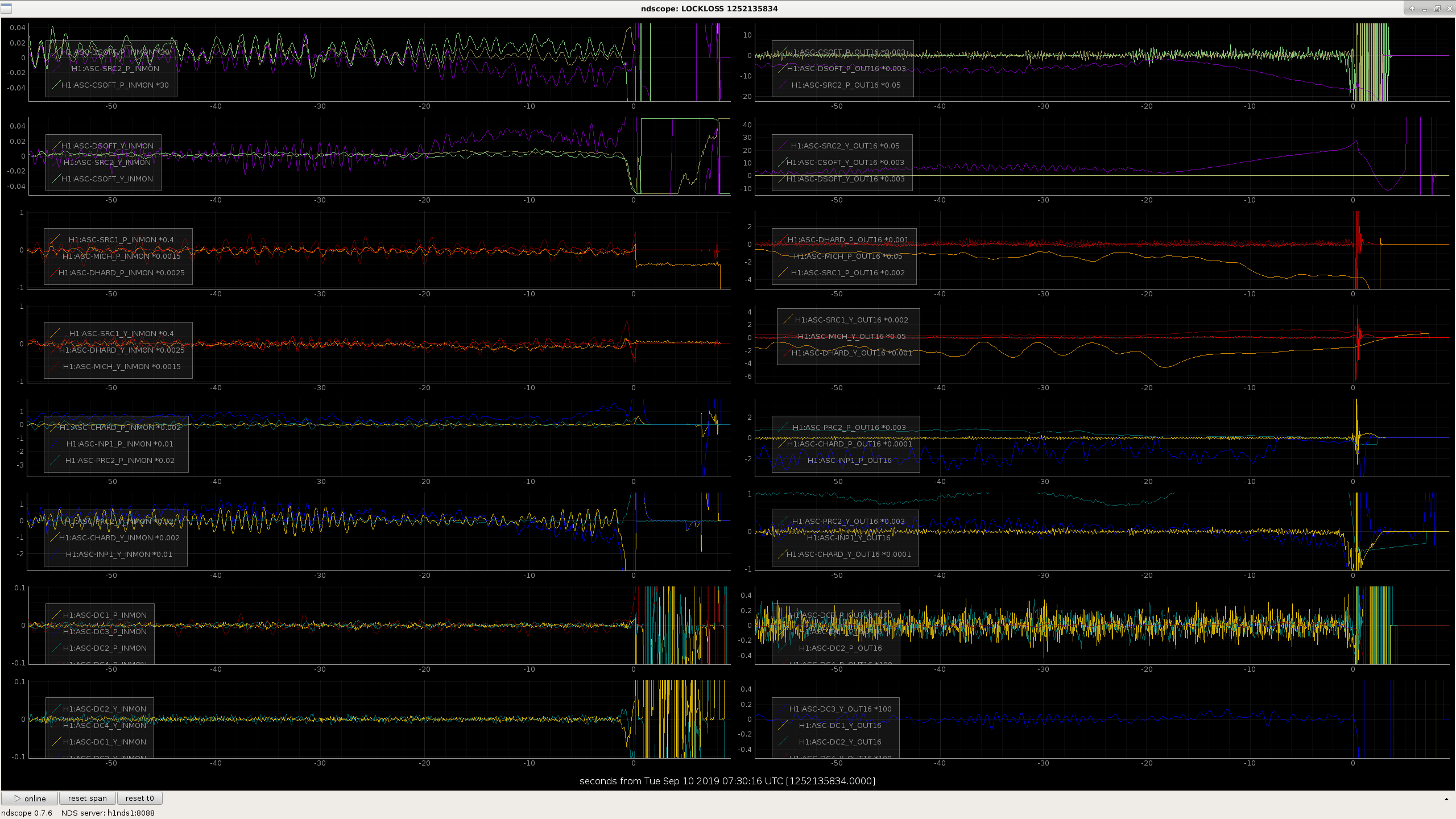
We didn't have any of the locklosses from ENGAGE_SOFT_LOOPS today. I did look at one of them from last night, and it does seem that we still have low gain in SRC2 (P+Y) and INP1 P so that the loops aren't holding their error signals around 0 in these steps. Speeding these up a bit might help us out here. Keita and I started to work on speeding up some of the ASC for similar reasons last Tuesday 51715, but we didn't get a chance to try increasing the gain in these very slow loops.
While running an Initial Alignment tonight, I was stuck at SRC alignment for quite a bit of time (I tried to address issue with various cycles of running down script, centering SR2 on AS_C, but had no luck).
Jenne tracked down the issue with guardian not liking where one of the SUS guardians was at (basically it thought one of the SUS guardians was actively changing). Sure enough this was tracked down to ITMx (If I remember correctly).
SYMPTOM:
SOLUTION:
After Jenne tracked down our sticky slider, she moved ITMx pit by 0.1 one way and back the other way, and as she did this (from Japan!) Guardian swung back into action and began to run through SRC alignment.
ACTION:
Notify TJ, Dave B, or Jaime about this issue since it has been a known issue to cause DOWN Time.
We've been seeing this issue for a while, although this might be one of the first times that I can remember it causing down time versus just general confusion (which is also not so good). Usually we see the yellow boxes stuck on after some alignment is offloaded via guardian in the main acquisition sequence, but they haven't seemed to stop the guardian from going forward.
As Corey reports, the ITMX pitch opticalign slider had it's is_ramping value stuck at True. The is_ramping value is what makes the boxes yellow when we ramp offsets or gains. This was causing the ITMX guardian to be stuck in MISALIGNING, and not getting all the way to MISALIGNED.
The ALIGN_IFO guardian is checking ITMX to ensure that it is fully misaligned before trying to lock the SRY cavity. Since ITMX was stuck in MISALIGNING and wasn't getting to MISALIGNED, the ALIGN_IFO guardian was stuck in PREP_SRY. To clear the is_ramping value, I clicked the ITMX pitch slider up one, and then back.
FRS filed here: https://services.ligo-la.caltech.edu/FRS/show_bug.cgi?id=13563
Since we went about 3hrs with constant locklosses for both Niko & I (along with two Initial Alignments by Niko), I decided to back out the IM change from last night which had a data point of the one lock we had since last night in the hopes of returning to the input pointing we had been running will help with locking.
IM Alignments Restored To Sunday Night Values:
IM1, IM2, IM3 restored to where they were before the last lock. (settings restored from SDF list here).
Initial Alignment:
With the new Input Pointing, I needed to run an Initial Alignment. Took a little longer than usual, due to....
Operator (me) Errors:
Error #1) IM Slider Mistake: Noticed Xarm in IR was not locking for INPUT_ALIGN. Couldn't determine the issue, buuuuut.....
--I had a commissioner monitoring remotely (from Japan!). Jenne let me know that one of the IMs was way off! I errantly entered IM2's Yaw slider (I added an extra "0" for it's value). After this I continued with alignment
Error #2) Green Y-arm Dead: Green Y had no light flashing! Probably due to me taking multiple Nodes to DOWN
--Once again Jenne helped me here, and she noticed my ITMy was waaaay off. I had noticed ITMy was labled as MISALIGNED, so I tried taking it to ALIGNED, but it wouldn't work. So I did a MANUAL to ALIGNED & then back to AUTO, but this misses steps. So Jenne had me take it to MISALIGNED, and then to ALIGNED, and this finally gave us light flashing in the Y-arm.
Error #3) Possible Sticky Slider: During alignment, SRC was continually stuck at around PREP_FOR_SRY
--Jenne tracked this down to an optic not in state Guardian liked. I believe this was ITMx & the issue was a "sticky slider". Will make separate alog for this.
Current Status: Just had my first lock attempt after restoring IMs and doing an alignment. Had lockloss at ENGAGE SOFT LOOPS. This was fairly early on this step & did not see any obvious reasons for the lockloss.
Additional NOTE: IMC guardian node has flashes of a notification of "IMC WFS not centered". This messages flashes quick, has been occurring fairly frequently, and is new to me.
ADDENDUM: Did NOT Revert IMs to Sunday night values!
I thought I had reverted the IMs back, but when I finally made it back to OBSERVING I noticed that there were no SDF diffs for SUSIM for me to ACCEPT!
I think the problem for my brain was that after I made the error in restoring IM2's Yaw slider (adding an extra "0" which Jenne caught), my mind had me sticking with all of the new IM slider values (vs the old slider values I wanted to revert to)!!! So I ran an Initial Alignment thinking the input pointing was referted, but it really wasn't. Grrrrr! My Mistake!!
Since it has taken roughly ~5hrs of locking to get us back to OBSERVING (+ 2hrs of my aligning), I'm still thinking we want to back out the IM pointing change from Sunday night since locking has been tough---IM values can be found here.
The IM1-3 slider values were reverted today (2019-09-10). See LHO aLOG 51858.
TITLE: 09/10 Owl Shift: 07:00-15:00 UTC (00:00-08:00 PST), all times posted in UTC
STATE of H1: Lock Acquisition
OUTGOING OPERATOR: Niko
CURRENT ENVIRONMENT:
SEI_CONF state: WINDY
Wind: 3mph Gusts, 2mph 5min avg
Primary useism: 0.02 μm/s
Secondary useism: 0.12 μm/s
QUICK SUMMARY:
Niko was locking H1 as I walked in. Made it further this last time to INCREASE POWER, but it lost lock early on in this process (drats!). I'm going to give it one more try, as is, and if have no luck I will try more active changes to get us back.
Right as we were locking, received a "long GRB" notification (notified other operators on Teamspeak). Then we received a second "regular?" GRB notification for the same event. Acknowledged both.
OK, back to locking H1!
TITLE: 09/09 Eve Shift 23:00 – 07:00 (16:00-00:00), all times posted in UTC
STATE of H1: Locking
INCOMING OPERATOR: Corey
SHIFT SUMMARY: Lockloss about halfway through shift, had trouble getting ALSY flashes high enough, and then poor flashes with PRMI/DRMI, so I went to initial alignment. BS seemed off afterwards, lost lock twice from ENGAGE_SOFT_LOOPS, tried an initial alignment again with MICH_DARK_LOCKED.
LOG:
15:00 (08:00) Start of shift
23:23 (16:23) Chandra to MX -- bring back gas bottles
00:24 (17:24) Chandra back from MX
00:41 (17:41) GRB (E349997). Trigger duration short, standing down for 15 minutes
01:00 (18:00) Ethan to Optics Lab
01:26 (18:26) Ethan out of Optics Lab
04:39 (21:39) Lockloss after glitch
05:04 (22:04) Not seeing strong flashes, going to initial alignment
05:36 (22:36) Initial alignment complete, starting to re-lock
06:24 (23:24) Two locklosses from ENGAGE_SOFT_LOOPS. Trying initial alignment one more time.
06:41 (23:41) Initial alignment complete, re-locking
07:00 (00:00) End of shift
Ops Shift Transition: 09/09/2019, Eve Shift 23:00 – 07:00 (16:00-00:00) - UTC (PT)
State of H1: Locked
Intent Bit: Observing
Weather: 10-30 mph wind
Primary 0.03 – 0.1Hz: 0.01 um/s
Secondary 0.1 – 0.3Hz: 0.1 um/s
Outgoing Operator: Ed
Quick Summary: High wind, not much going on other than that. Locked for ~18 hours, Observing for 5 hours.
TITLE: 09/09 Day Shift: 15:00-23:00 UTC (08:00-16:00 PST), all times posted in UTC
STATE of H1: Observing at 113Mpc
INCOMING OPERATOR: Niko
SHIFT SUMMARY:
LOG:
16:30 H1 Observatory mode to Calibration for installation of new calibration model - Jeff K
16:32 Intention bit Commissioning
17:38 Kyle out to MY to lock/tagout scaffolding as unsafe to climb on
17:43 Karen out to MY
18:01 Kyle back
18:20 Karen back
18:26 Intention bit Observing
20:43 Kyle to MX - looking for shop vac
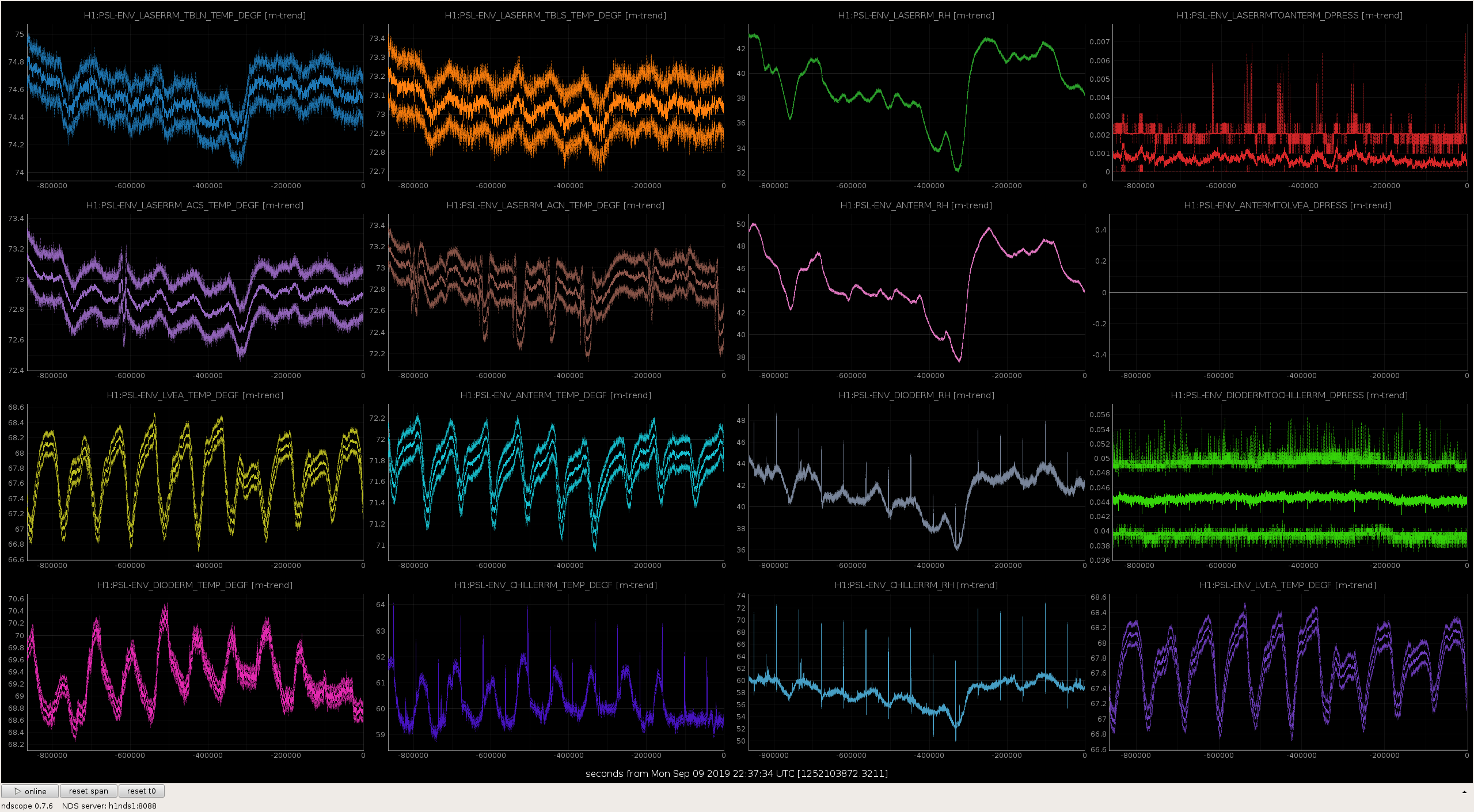
All seem ok
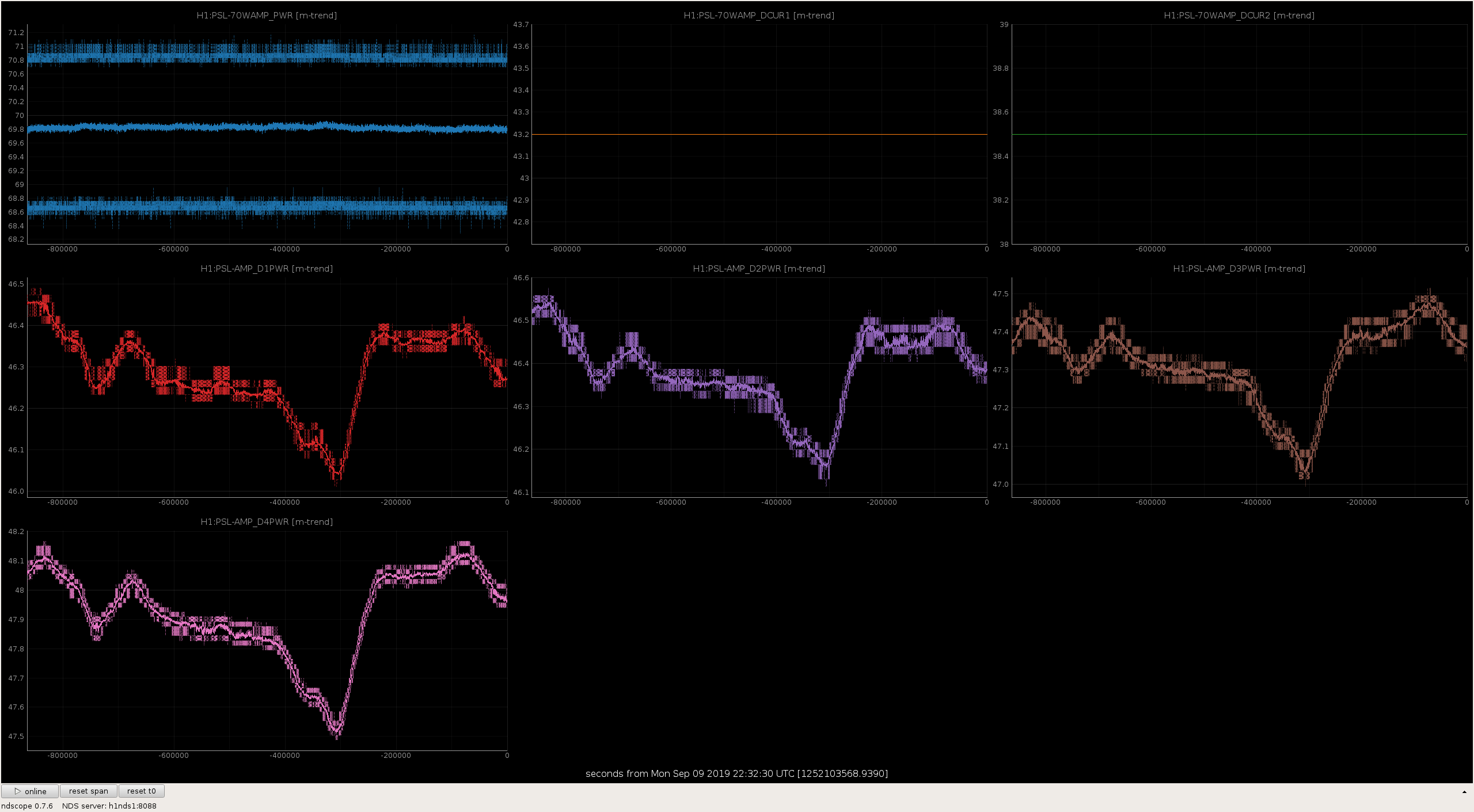
Laser Status:
Front End Power is 32.01W (should be around 30 W)
70W Output Power is 69.7W
Front End Watch is GREEN
70W Watch is GREEN
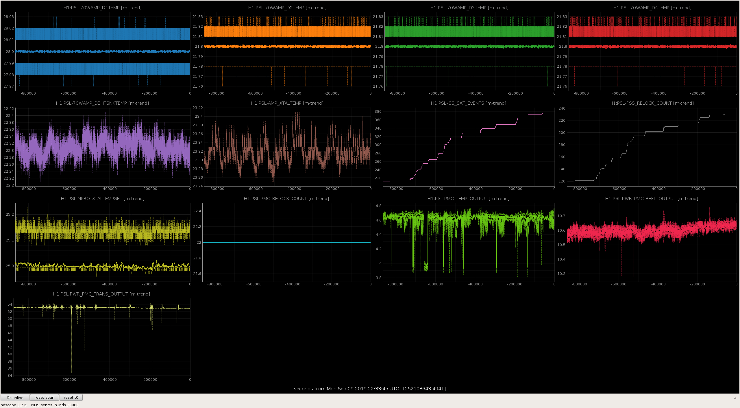
PMC:
It has been locked 11 days, 3 hr 37 minutes (should be days/weeks)
Reflected power = 10.65Watts
Transmitted power = 52.96Watts
PowerSum = 63.6Watts.
FSS:
It has been locked for 0 days 16 hr and 0 min (should be days/weeks)
TPD[V] = 5.015V (min 0.9V)
ISS:
The diffracted power is around 2.2%
Last saturation event was 0 days 16 hours and 1 minutes ago (should be days/weeks)
Possible Issues:
A couple of weeks ago week Jeff and I took a series of measurements of the sensing function, cross correlation, and squeezing level for different phases, at different spot positions and different squeezing angles. (51394, and 51440) There is still more work to be done to understand the measurements, but some first conclusions are: There are frequency dependent losses for squeezing which are larger above the cavity pole, and didn't change much with the spot position change, although the cavity pole and the reflectivity of the CLF sidebands did change with the spot positions.
Background: We had tried before O3 started to move the SRCL offset and see a frequency dependence of the squeezing level, but we saw no impact. I repeated this in July and found that with reduced frequency noise, and subtraction of correlated noise, we can see some frequency dependence, and a bit better squeezing at low frequencies for some SRCL offsets 50591
Lee has done some modeling of some frequency depenent losses, squeezing angle rotations, and an apparent frequency dependent phase noise due to SRC losses, SRC to ARM mode mismatch, and SRC detuning. 50610 Lee showed there that with SRC losses and a mode mismatch between the SRC and the arms, it is possible that the squeezing is flatter for a detuned SRC than for an anti-resonant one, and that SRC losses degrade the squeezing at high frequencies while SRC to arm mode mismatch degrade the low frequency squeezing. Since we were planning to move our spot positions, and we know that this has an impact on the DARM pole, I wanted to try to get some measurements that could be usefull to compare to that modeling.
Optical spring /DARM pole:
Jeff has posted some of the sensing function measuerments that he did in these alogs: 51440 and 51592. The short story is that we can have much less of an optical spring effect with 100 cnts offset in SRCL for both spot positions, indicating that 100 counts offset is really closer to the SRC anti-resonance, and we are now running that way. We lost lock trying a 200 count offset, which gave us an anti-spring based on the partial sensing function measurement Jeff was able to get. (2nd attachment) The calibaration group fits a single pole to the DARM cavity pole, this causes a few percent error in the calibration around and above the cavity pole for the kind of SRC detunings we have been running with in the first part of O3, which can be seen in the attachment linked above. According to Jeff's use of Craig's model of the optical spring and DARM response here the detuning of the SRC that we have been seeing is around 6mrad, although something seems off here since the phase is not matched well above the cavity pole in those models.
Squeezing:
The first attachment shows the squeezing level, based on DCPDs with the correlated noise subtracted as described in 50591 The first attachment shows all 4 sets of measurements, in all of them there is more squeezing and more anti-squeezing at low frequencies which would indicate lower loss below the DARM pole. The measurements taken at phases intermediate between squeezing and anti-squeezing give us the best information about the frequency dependent squeezing angle rotation, although a little bit of thought is needed to interpret these. (In the legend I labeled each trace with sqz or asqz based on the sign of the CLF servo, and the phases are from the CLF phase shifter). The three sets of stars are estimates of the mean squeezing level in three frequency bands.
The second attachment shows all measurements at the nominal squeezing phase and the nominal anti-squeezing phase, for easier comparison. Abvove about 500 Hz all the measurements are basically the same, and at low frequencies the differences in the squeezing levels between them are small. There is some suggestion of less loss (or at least more sqz/asqz) at low frequencies for the July spot positions and with the SRCL offset on, which could be compared to the first plot in Lee's alog. Based on the level of squeezing and anti squeezing seen at these nominal angles (which are not very different from the best squeezing and anti-squeezing for each frequency), we can make an estimate of the total efficiency and phase noise for each measurement frequency. Since there are many lines in the data which give impossible results if we interpret them as squeezing and anti-squeezing, I've limited the data used for making these estimates based on the level of squeezing and anti-squeezing. The 5th attachment shows the resulting estimate of efficiency, with the budgeted losses divided out, which shows higher losses at frequencies above a few hundred Hz, which Lee's modeling suggests could be because of squeezing matching to the IFO or because of SRC losses. We have basically the same result for frqeuency dependent losses for all the spot positions and SRC detuings, although the cavity pole increased from 409Hz to 415Hz when the spot position changed (for the measurements with no/small detunings 51466). By comparing the change in the cavity pole to the lack of a change in frequency dependent losses using Lee's model we might be able to make a statement about if the cavity pole change was (or wasn't) due to a change in SRC losses, or perhaps could rule out SRC losses as an explanation for the frequency dependent losses that the squeezer sees.
The inferred efficiency increaes right around 2.3kHz, which is due to an increase in the anti-squeezing level, and is an interesting feature. I wouldn't read too much into the infered phase noises in this plot, as there is a lot of scatter.
Squeezing level as demod phase rotates:
To estimate the losses discussed above, I used measurements made at the same demodulation phase for all frequencies. There is a potential problem with this because the frequency dependence of the squeezing angle could be contributing a bit to the apparently higher losses at higher frequencies, but it should not be a large effect because none of the other squeezing angles had much more squeezing or anti-squeezing than the measurements used here. The third attachment shows the median squeezing in different bands plotted against CLF demod phase for each SRC offset/spot position combination. These plots suggest that we could get better squeezing at low frequency if we continued to reduce the CLF demod phase, although this may not have much of an impact on our sensitivity. I had hoped to fit each of these sets of measurements to get an estimate of loss, phase noise, and the squeezing angle rotation for each band to avoid the problem of using one demod phase to estimate squeezing and anti-squeezing for all frequencies. The problem with that is understanding the relationship between the CLF demod angle and the squeezing angle (see Daniel's expression here 49026). For most of these measurements the clf demod phase between anti-squeezing and squeezing is around 130 degrees, which I don't have an explanation for at the moment.
LO Q signals:
Because the 130 degrees between squeezing and anti-squeezing made me wonder if the phase shifter calibration was off, I plotted the LO Q signals normalized by the CLF reflected power (the normalization is needed since there were CLF power jumps durring the measurements) and made fits (4th attachment). Fitting these with an ellipse works well, and it seems that the calibration of the phase shifter is fine. The most interesting thing to see is that the OMC 3 MHz signal ellipse has a larger semi-major axisis with the July spots than it does with the August spots, indicating that the reflectivity of the SRC for the CLF changed when the spot positions changed. There were also small shifts in the demod angle of semi-major axisis when the SRC offset was changed, although this is small.
| semi-major axis (uncalibrated) | eccentricity | shift of semi-major axsis (clf demod deg) | |
| August spots no srcl offset | 1.35 | 0.82 | -84 |
| August spots srcl offset 100 | 1.35 | 0.81 | -83 |
| July spots no srcl offset | 1.43 | 0.8 | -76 |
| July spots srcl offset 100 | 1.41 | 0.8 | -81 |
Next steps:
There are several things that could be done next, including comparison to Lee's model for the cavity pole change, modeling of the 3MHz OMC DCPD error signal, infering a squeezing angle rotation from the intermediate squeezing angle measurements, measureing the squeezing at lower clf demod phases, and measuring squeezing at the intermediate angles for different SRC offsets.
[L. D'Onofrio, G.Vajente]
Using Band Limited RMS [1][2], we tracked the variation of the detector noise during O3 data.
There are evidences that part of the variation in the BLRMS time series in the frequency band 1120-1400 Hz is linked to channels that belong to PSL subsystem.
Our model does not explain all the variation of the BLRMS segment.
To find correlations between the variation of noise and the auxiliary channels (we chose 10 subsystems, around 80 thousand of channels) we used LASSO (for more details, see [3].
To quantify the “importance” of channels selected by LASSO we defined the ε score that is the normalized residual computed for single channel (0< ε <1; ε ∼ 1 means no correlation).
We analyzed different BLRMS segments in the last four months of O3 data.
We obtained the best reconstruction for the 22-hour BLRMS segment starting from 1249000652 GPS time (Aug 05, 2019 00:37:14 UTC). This segment is splitted in two equal parts; the first part is the training set for LASSO and the second part, the test set. In Figure 1, the top plot shows the predicted values (in orange) using the 4 channels selected by LASSO while the bottom plot, the residuals for the test set.
The selected channels are:
In the shown BLRMS segment the residuals are close to zero and the reconstruction is good. This does not happens for all the analyzed segments. Further analysis is required.
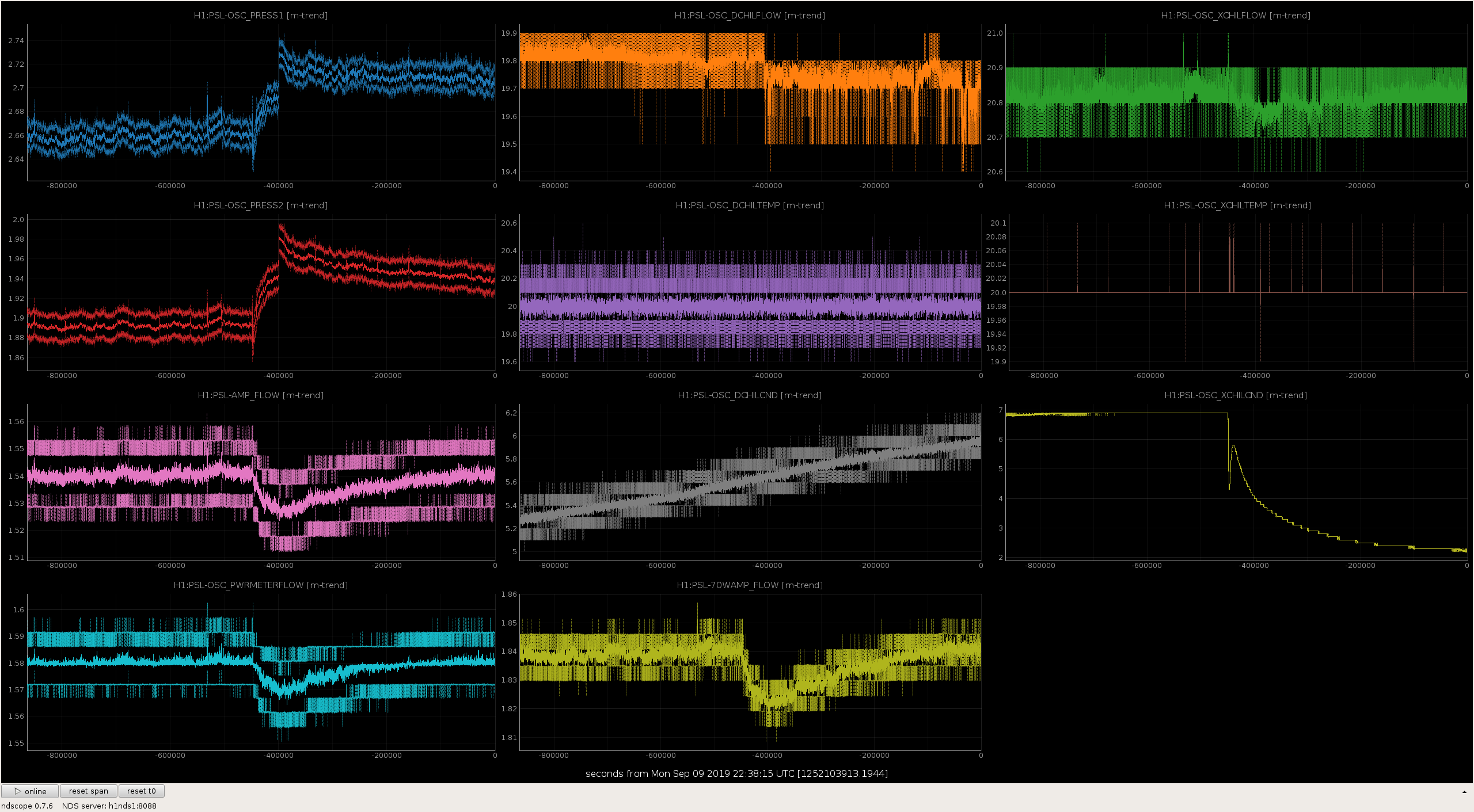
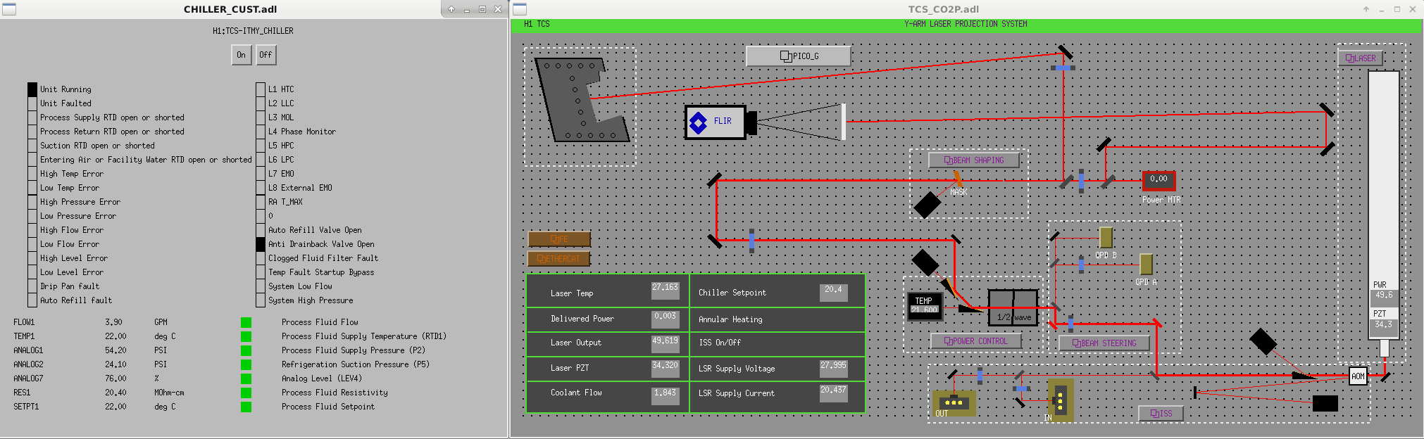
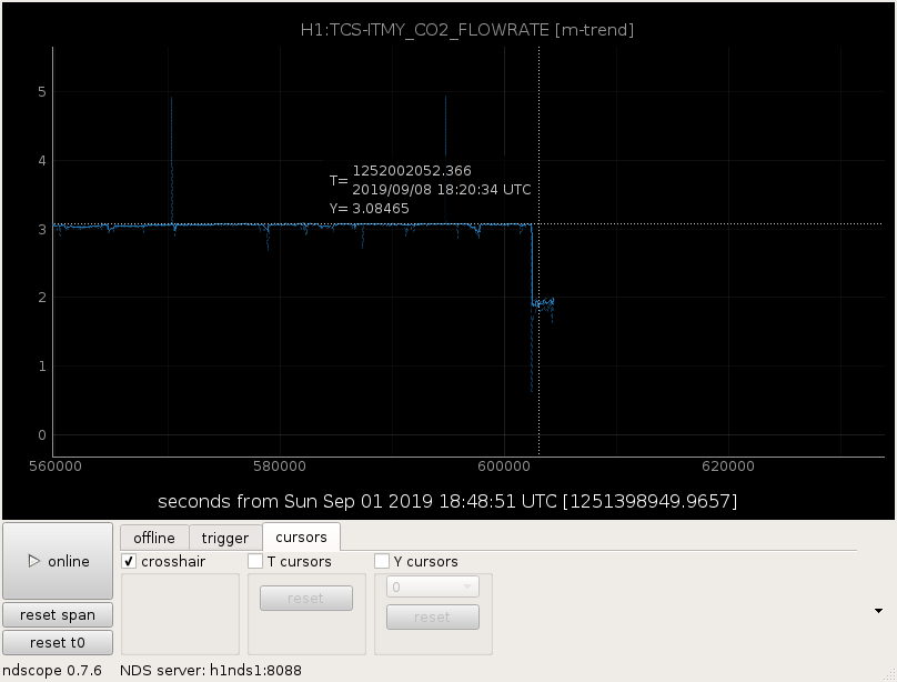
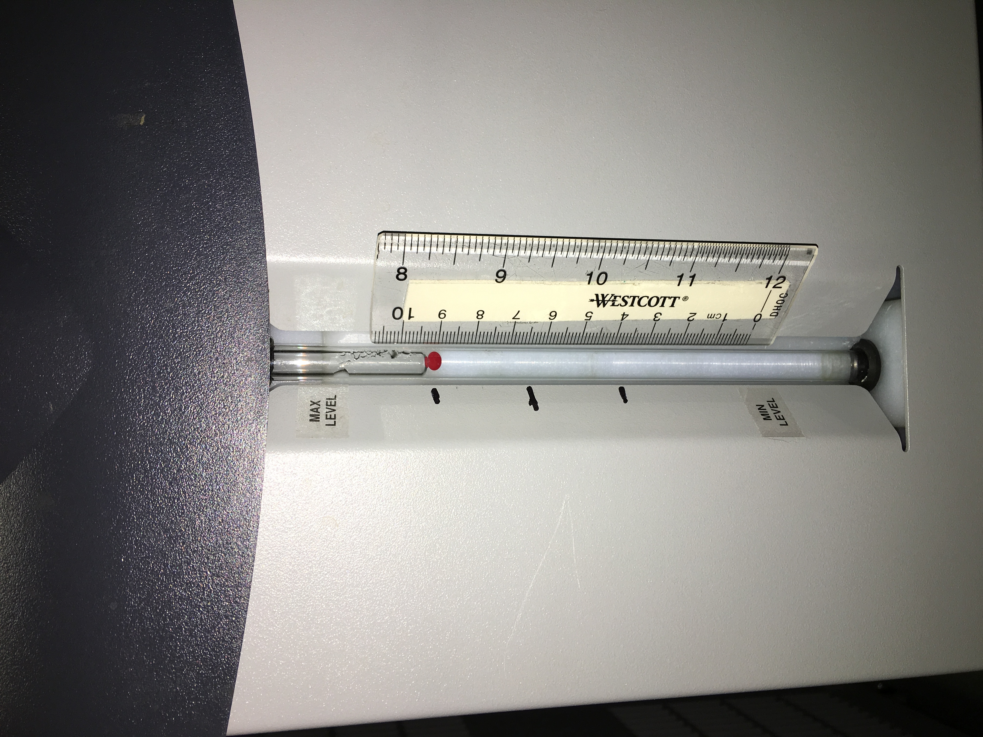
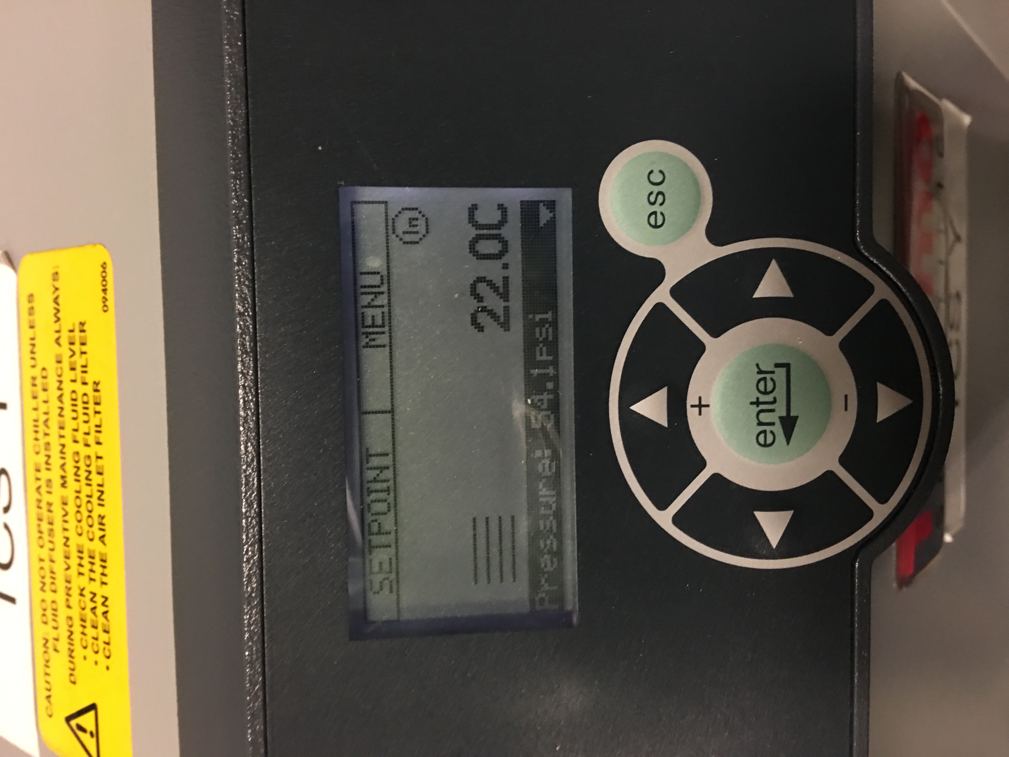
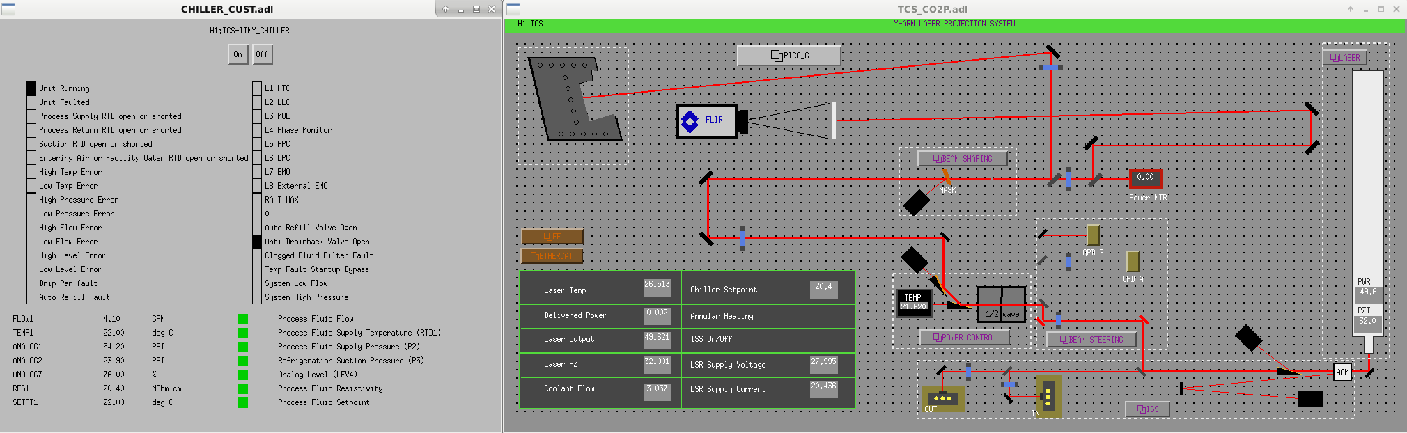
I got this verbal at 18:23UTC. I contacted TJ before trotting off to the mechanical room. We found that the 'CO2 Y' & 'CO2Y CHILLERS' screens show a discrepancy in flow rates. I went out to the chiller and found that the water level was at 9 (down from 10) so I added 50ml. At 18:55, after I returned to the CR I got another verbal. Trending shows this sudden drop in flowrate (possible leak) or possibly sudden malfunction in flow meter?
After Wednesdays commissioning discussion, I added mode-mismatching to the cavity model used in 50589 to enable internal SRC<-> ARM mode mismatch in its 2-mode rotation-matrix approach. This is to study how relevant the internal mode-matching is to squeezing and frequency dependent degradations to shotnoise. Internal mode matching is a bit more tricky, as the "best" operating point for the cavity model becomes non-trivial. Finesse and other transverse-mode capable simulators have tools to tackle this problem, but I'm not aware if any lock-point optimizers which handle squeezing in a simple manner. Because of frequency-dependent degradation, optimizing lock points is not uniquely defined and in principle, optimizing SQZ'ed spectra for BNS range or "science case" is the most general solution. Unfortuantely, this kind of optimization is very opaque for complex simulations.
I derived a few metrics to make finding lock-points more tractable for this two-cavity SRC+IFO simulation. Past studies have focused on the SRCL tuning - to optimize the sqz angle rotation, and measuring SQZ Loss and phase noise. There is one more important degradation that has not been studied in interferometer measurements or simulations. This is the loss imbalance in upper/lower sideband transfer of the squeeze field. This effect is known from how it can degrades the filter cavity operation, and not previously expected in the interferometer operating in its nominal SRC/ARM tuning. In T1900446 I derive the metrics, and show that the parameter "d", related to unbalanced loss in the arms, will cause a degradation that behaves identically to phase noise, except in a frequency-dependent manner. It also shows concise formula to help set the operating point of the squeezer in a simulation. The similarity to phase noise means that it is an irriducible coupling of anti-squeezing into the observation quadtrature (phase).
The reason that loss imbalance couples anti-squeezing is that the squeezing relies on a magnification of quantum noise from parametric gain, with a corresponding correlation in the upper and lower sidebands that allows them to strongly cancel in the readout (despite the magnification). The squeezing angle modifies the correlation from cancelling to adding, rotating from squeezing to anti-squeezing. Phase noise is a background modulation of the rotation between the two. Loss imbalance removes the correlation, but not the magnification to the noise, which also causes irriducible anti-squeezing. Loss imbalance in the SRC reflected sidebands could potentially account for the apparent phase-noise excess observed at both sites.
The question is whether after fixing the sqz-angle detuning (SRCL offset), there can be imbalance in the loss on sidebands of the SRC reflection, even with the sideband phasing well-balanced. It appears that this is possible. It is a weak contribution with loss and mode-mismatch within the SRC. For mode-mismatch outside of the SQZ to IFO, the contribution is much stronger, altough in this model does not saturate the observed excess phase noise.
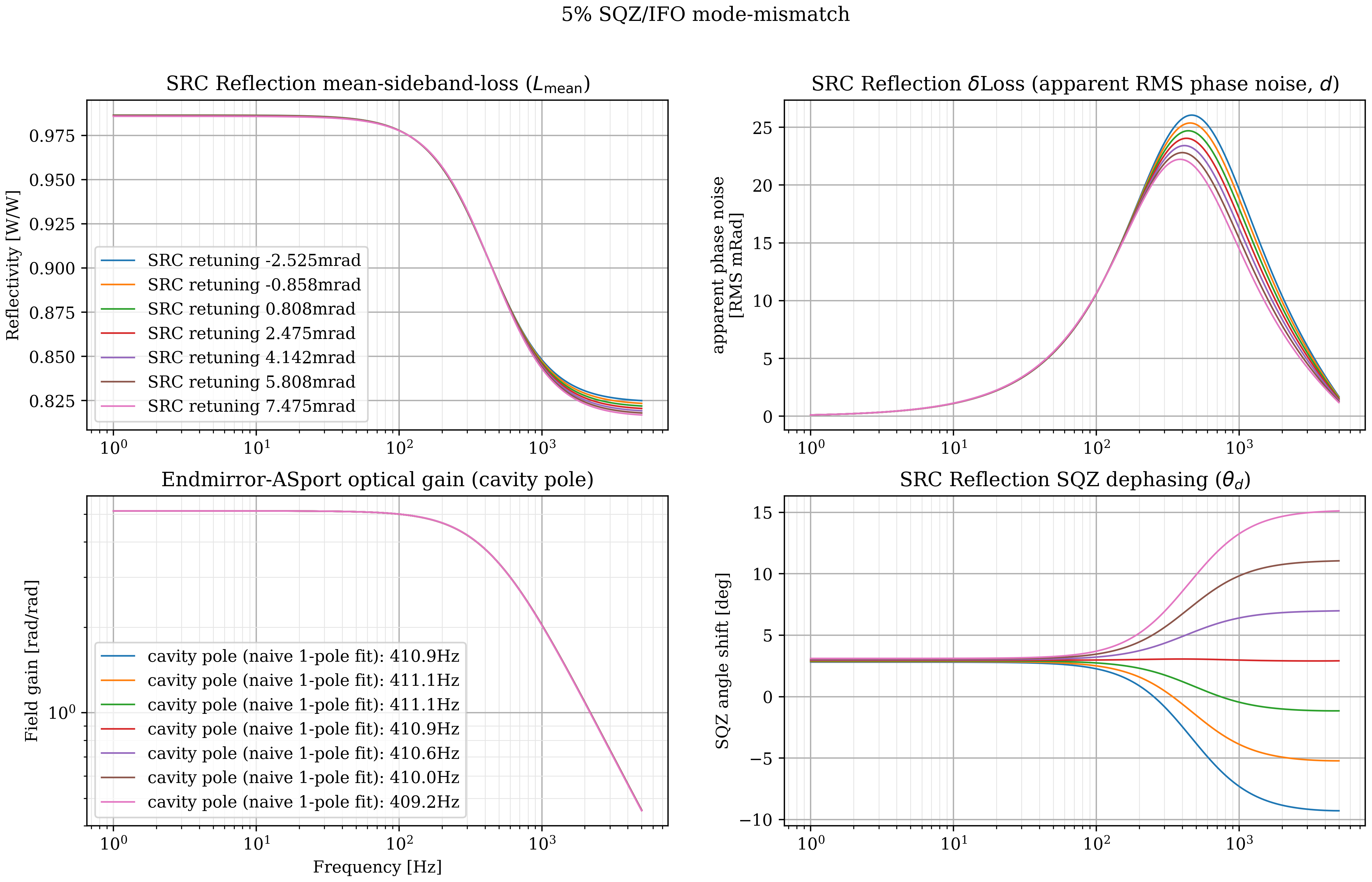
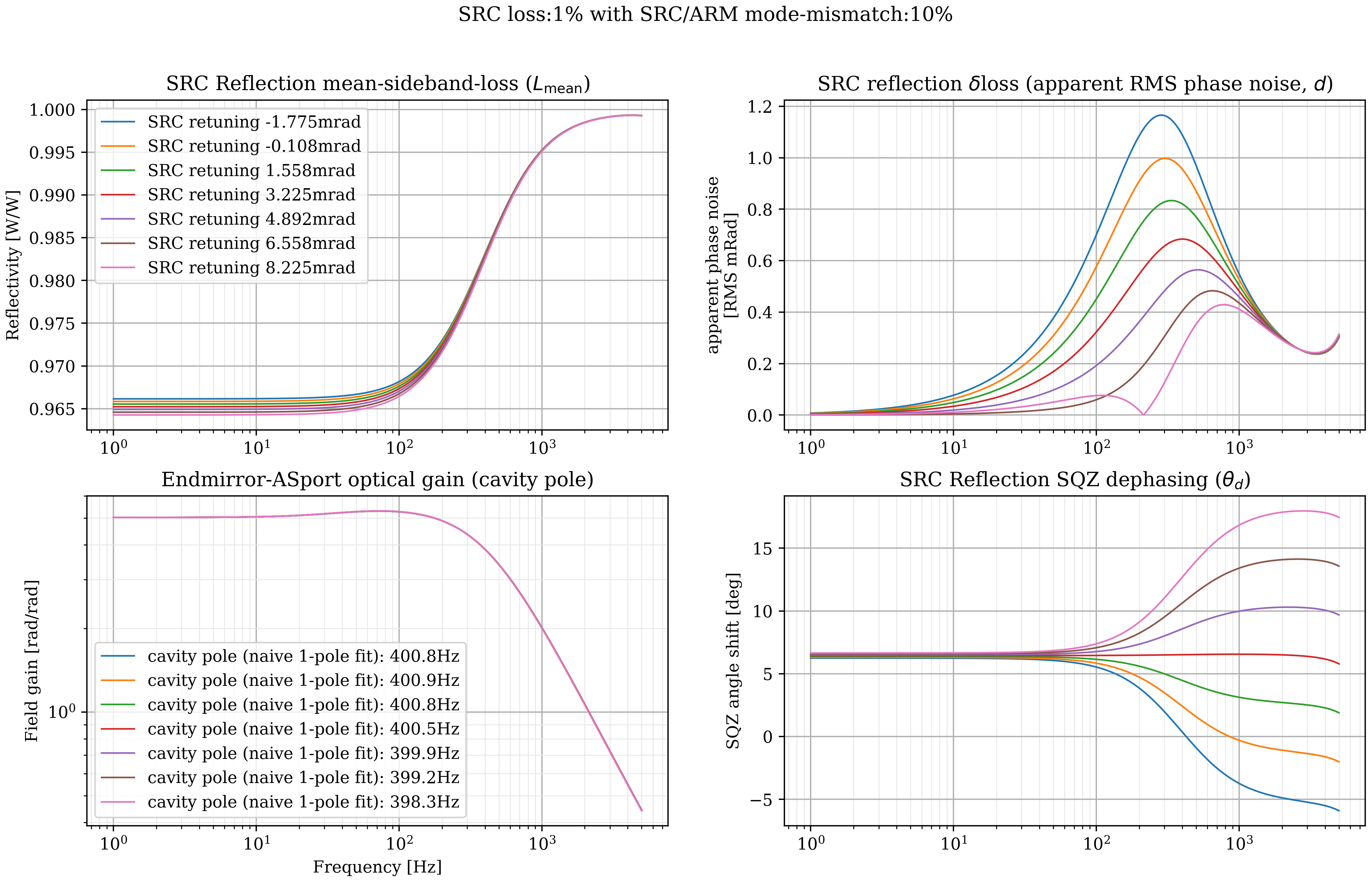
cavity_pole_SRCtuningSRCmm.png shows a set of transfer-functions of the 00-mode reflecting from the SRC. The mode-matching of the SQZ to the IFO is perfect, but the SRC has 1% loss and 5% mode-mismatch to the arms. The code in coupled_cavity.py shows the full equations for the cavity reflection in the function coupled_cavity(...). There the 2-mode cavity model is applied to both upper and lower sidebands, giving
r_src(+F) and r_src(-F)
which is initially nF x 2 x 2 matrix for the HG00 and HG02 modes modeled. Here, only the HG00->HG00 coupling is used, since the mode-matching to the OMC is assumed perfect, so r_src is a scalar. This r_src is the h(f) in T1900446.
arg(r_src(+F) * r_src(-f))/2 is the squeezing angle upon reflection from the cavity. This is the lower-right plot. The SRC tune-phase (Shiela's SRCL scans 50591) is adjusted and optimized to flatten the squeezing angle, showing that there is a tuning which has no residual frequency depenence to the squeezing angle. This is observed as having the optimal noise independently at each frequency.
abs(r_src(+F) * r_src(-f)) is the upper-left plot, the (geometric) mean sideband Reflectivity. This is related to how much unsqueezed vacuum creeps in. min/max(abs(r_src(+F))**2, abs(r_src(-f))**2) sets bounds on this number. The "c" and "L_mean" metrics are similar and nearly equal to this, but, when the losses are substantially different and these loss metrics show some discrepancy, the noise will not be dominated by the vacuum, but rather the loss-imbalance, so the geometric mean is a sufficient heuristic.
When the upper/lower sideband reflectivity losses are different, the imbalance is expressed by
d = abs(abs(r_src(+F)) - abs(r_src(-f)))
This is shown in the upper right. This is a rather conceptually-opaque expression, but is derived to act just like RMS phase noise.
The lower-left of the plot is the cavity pole. At this level of mode-mismatch the DARM sensitivity has a considerable pole-splitting. The fits are using only a naive single-pole, but it is reported as a figure-of-merit to relate to the current/past cavity poles. It is surprising that an operating point exists with a flattened SQZ angle despite the pole-splitting, which is from a single optical pole aliasing to different frequencies in the upper-lower -> quadrature sideband projection. Such aliasing causes frequency effects on the angles that would not be expected to cancel so exactly without also cancelling the pole-splitting. It must be that the DARM-xfer and SQZ SRCrefl xfer sample sufficiently different things that this is possible. These transfer functions might suggest that SRCL tuning should not affect calibration, but RPN is not included and the optical-spring effects are missing.
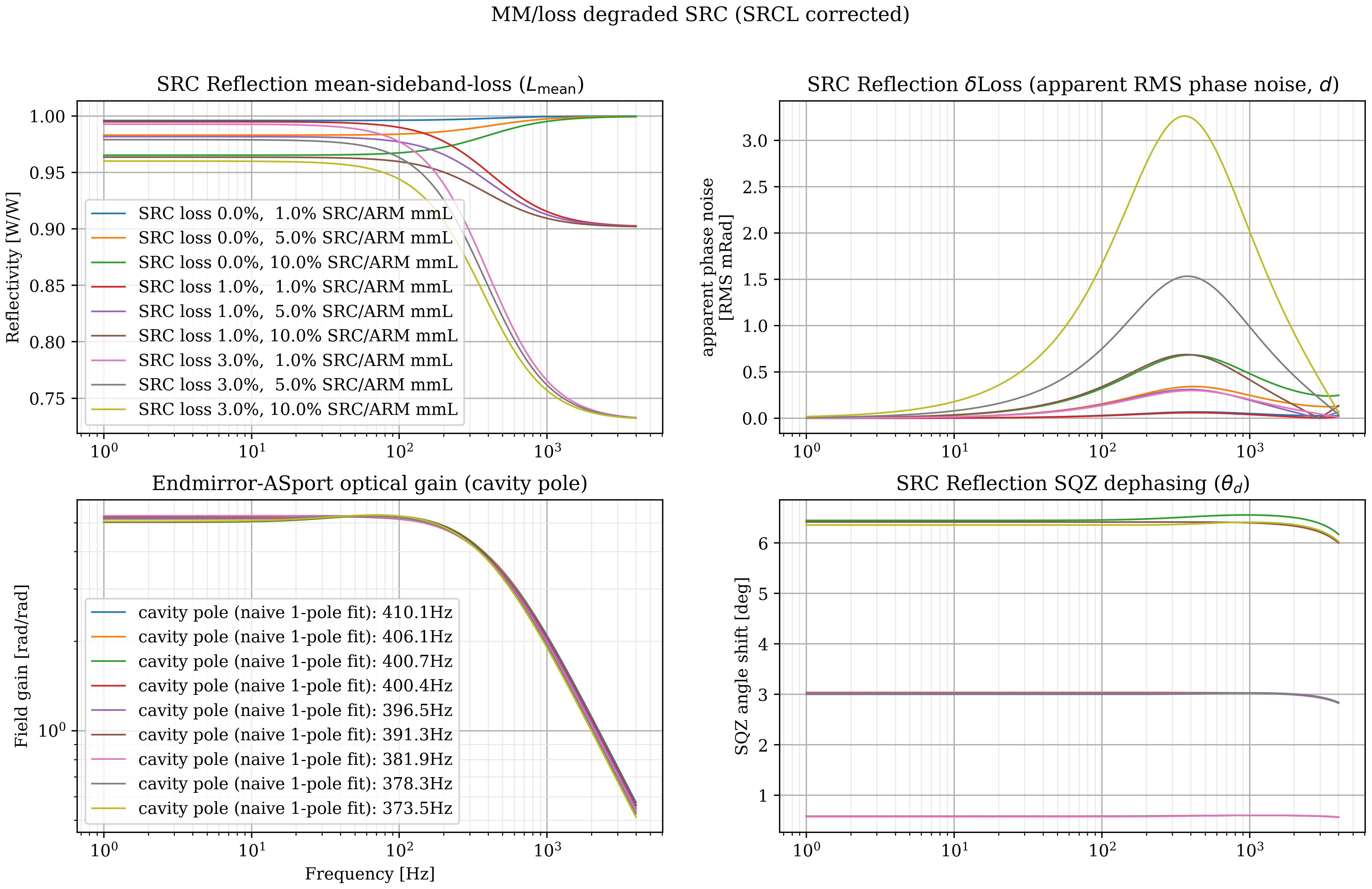
cavity_pole_SRCtunedSRCmm.png Performs the same analysis, where the SQZ-angle shift is always optimized for flatness, and the SRC mode-mismatch loss and dissipative losses are varied. These show that further degradation strongly affects loss at high-frequencies (from SRC loss), but these do not affect loss-imbalance significantly.
Now, introducing mode-mismatch between the SQZ and IFO gives a different story.
cavity_pole_SRCtuningIFOmm.png shows the metrics with 5% SRC/ARM internal mismatch loss, as well as 5% SQZ/IFO. The curves show different SRCL tunings. At high-frequencies this large IFO mismatch causes a large effective loss, and at intermediate frequencies, it causes substantial phase noise as well (although not as much as we are looking for).
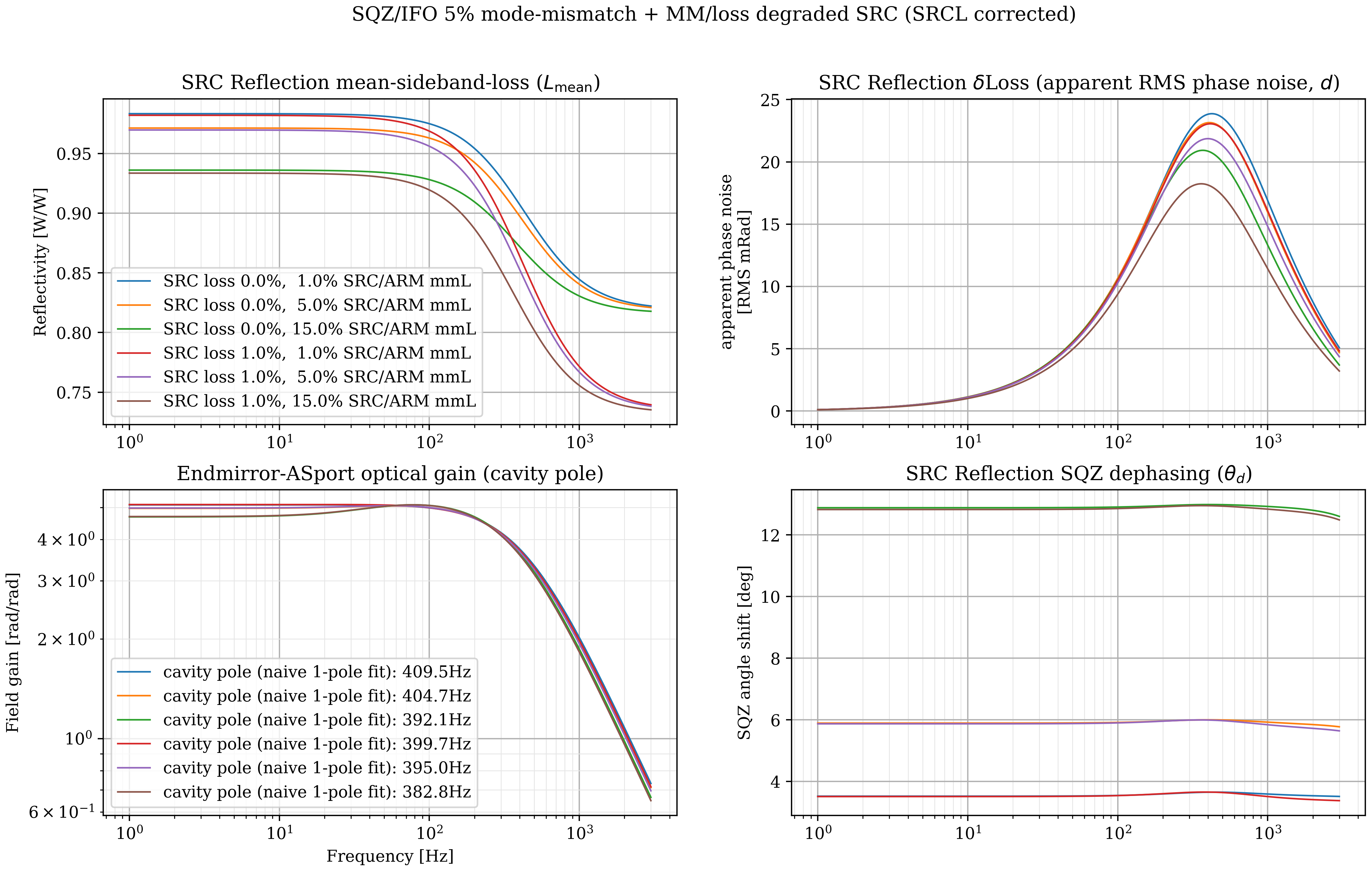
cavity_pole_SRCtunedIFOmm.png Shows 5% SQZ/IFO mode-mismatch, with tuned SRCL, but varying the SRC loss and SRC/ARM mismatch.
From some studies not shown, the differential loss (apparent phase noise) is affected by the SRC Gouy phase (I am using .345rad, 19.8 deg, or .11/FSR single-pass for the HG02). When the Gouy is decreased, the loss-imbalance grows. This suggests that a model of HG01 alignment noise, using less Gouy from the lesser mode, will show larger degradation.
I matched these Gouy phases by using this model to simulate Jon Richardson's measurements in LLO39779 Interestingly, those measurments show a 30db dip in SRC reflectivity! This can indeed happen when mode-mismatch is bad, and similar measurements (at lower frequencies) may be useful in the future to characterize SQZ degradations.
Although this model does not saturate the observed losses and phase noise, It suggests that further studies of the controls noise may show substantial contributions from residual motion RMS. A more complete simulation will also be insightful and hopefully these metrics will be useful for even more complicated models. Loss-imbalance might be a canidate for the squeezing "phase noise" identified in advanced detectors.
Errata: The DARM transfer function resonance (lower left) that is visible is not right. The code has two matrix-multiplies switched, but only on the endmirror-to-OMC transmission that indicates the DARM transfer function. The other three squeezer plots and code should be OK. Fixing the matrices gives no resnant feature, but does predict DARM pole changing.