TITLE: 07/03 Day Shift: 15:00-23:00 UTC (08:00-16:00 PST), all times posted in UTC
STATE of H1: Calibration
INCOMING OPERATOR: Jim
SHIFT SUMMARY: Relocked without too much issue. Calibration measurements ongoing.
LOG:
J. Kissel
I've gathered the regular sensing function measurements this week. The file names are listed below.
/ligo/svncommon/CalSVN/aligocalibration/trunk/Runs/O3/H1/Measurements/FullIFOSensingTFs
2019-07-03_H1_DARM_OLGTF_LF_SS_5to1100Hz_15min.xml
2019-07-03_H1_PCALY2DARMTF_LF_SS_5t1100Hz_10min.xml
2019-07-03_H1_PCALX2DARMTF_LF_SS_5t1100Hz_10min.xml
2019-07-03_H1_PCALY2DARMTF_BB.xml
2019-07-03_H1_PCALX2DARMTF_BB.xml
2019-07-03_H1_OMCDCPDSUM_to_DARMIN1.xml
Since I'm now well-practiced in processing the "normal" measurements with PCALY, I've already got the answers from it:
Optical gain, H_c (ct/m) | 3.156e+06 (+1300,-1294) or (+0.04121%,-0.04101%)
Optical gain, H_c (mA/pm) | 4.213 (+0.001736,-0.001728) or (+0.04121%,-0.04101%)
Cavity pole, f_cc (Hz) | 406.9 (+0.7171,-0.7105) or (+0.1762%,-0.1746%)
Detuned SRC spring frequency, f_s (Hz) | 5.193 (+0.00917,-0.009293) or (+0.1766%,-0.179%)
Detuned SRC spring quality factor, Q_s | 99.09 (+6642,-1.452e+04) or (+1.492%,-0.6826%)
Residual time delay, tau_c (usec) | 0.6708 (+0.4446,-0.4449) or (+66.28%,-66.33%)
which means the MCMC computed TDCFs are
TDCF Parameter | Value
---------------------------
kappa_c = 0.97099
f_cc = 406.9
f_s = 5.193j #spring
Q = 99.09.
which are in as much of agreement as one can see from the 2019-07-03 (I'm still working on getting data these GDS-computed TDCFs quick so I can make a plot for you in which you can actually quantitatively compare).
J. Kissel
I've analyzed the measurement data we've taken to quantify the DARM loop's sensing function (via frequency-dependent sweeps) we've been taking since the start of O3. For each data set, I've fit the data using the standard MCMC technique, and plotted the equivalent of the time-dependent correction factors as a function of time and commissioning events.
See three attachments:
(1) The collection of all processed data plotted against its MCMC fit (note, none of these are corrected for time-dependence as we're trying to *expose* the time-dependence with these plots)
(2) A time series of the resulting MCMC fit parameters for each measurement that we *would* normally use to correct the data sets for time-dependence (note, we don't use those TDCFs computed by the calibration lines because the lines must be OFF during the sweeps to preserve PCAL actuator range)
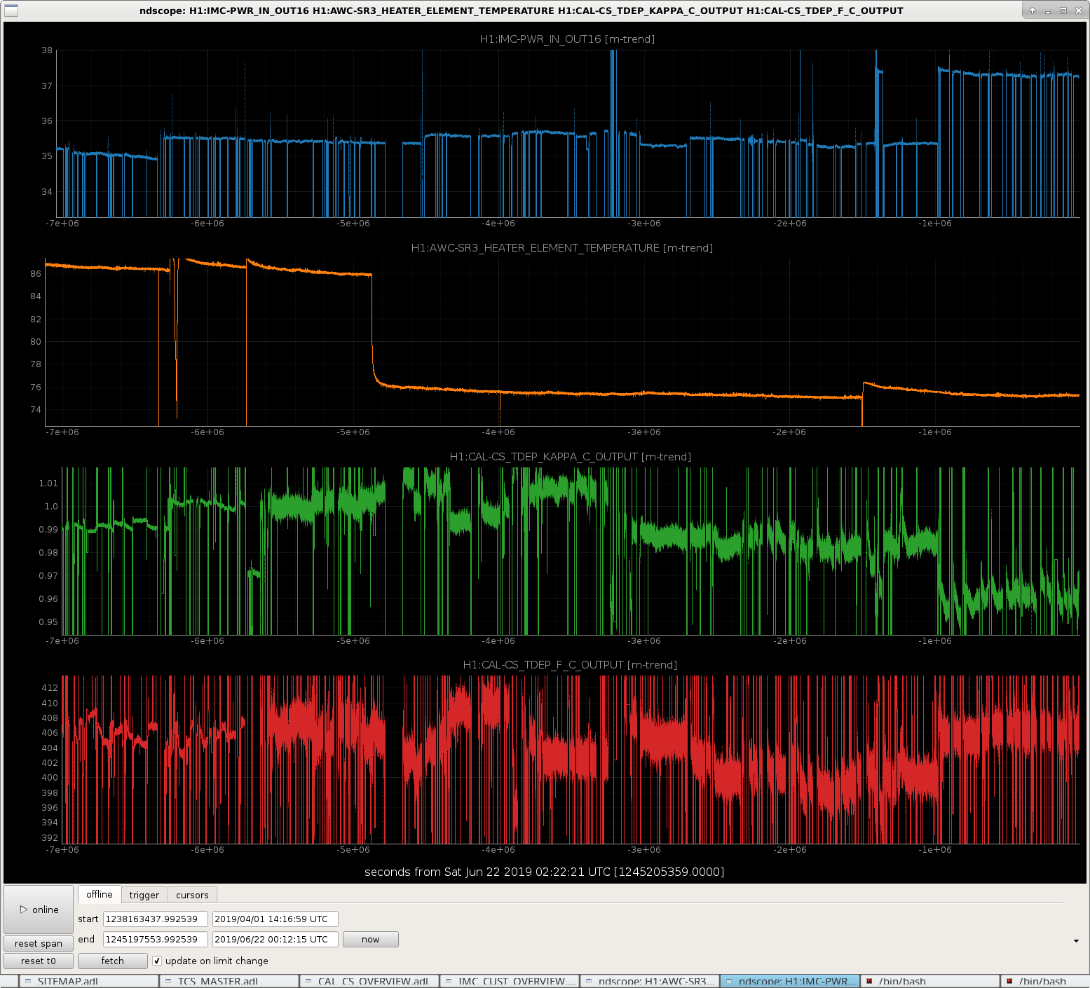
(3) A continuous time-series of (some of) the time-dependent correction factors as a function of measured PSL input power and SR3 disc heater. (note this trend was taken on 2019-06-21, so does not include the most recent sweeps from 2019-06-27, but the and no major commissioning events have happened since and IFO has been roughly stable.)
The commissioning events that I've highlighted that believe would have impact on the sensing function are as follows (all times UTC):
2019-04-01 15:00 O3 Start (PSL:35W, SR3:5W)
-- start of the observing run;measured PSL input power is (roughly 35 W), and the SR3 disc heater is set at 5W.
2019-04-26 16:51 SR3 Heater 5W>4W, Pwr Osc Start
-- when the SR3 disc heater is first reduced from 5W to 4W requested power, a drop in measured temperature on its thermistor from 87 [deg C] to 75 [deg C]. From here until May 10, the ASC system is not tuned, which results in large (1% level, 2 minute period) power fluctuations in the arms.
2019-05-10 05:45 ASC Tuned Up, Pwr Osc Fixed
-- ASC system tuned up, no more oscillations
2019-06-04 15:45 SR3 Heater Power Fail
-- The disc heater power failed due to some computer problems. Upon restart, the temperature started out a bit high, and did not settle back in to "nominal" 75 deg C until a few days later.
2019-06-10 18:17 PSL Power 35W>37W
-- major commissioning effort to increase the laser power from "35W" (roughly) to "37W" (roughly) succeeds and we start permanently running at "37W."
2019-06-11 15:00 SR3 Heater Temp Stable
-- here's when the SR3 disc heater temperature recovered to 75 deg C and has remained there.
One can see lots of things:
(A) by looking through the processed measurements of the sensing function, one can clearly see that
(i) the MCMC is still not doing a quality job at fitting the detuned SRC optical spring. Some argue that this is not an optical spring, but an artifact of our drive system and L2A2L coupling, but for the purposes of this entry, and for lack of a better term, we'll continue to call it the detuned SRC opical spring.
(ii) There is no obvious change in shape between 2019-04-17 and 2019-05-02 measurements when the SR3 disc heater power was reduced from 5W to 4 W.
(iii) The shape of spring changes significantly between 2019-05-09 and 2019-05-22, remains the same until the 2019-06-10 measurement, just after the power up from 35 to 37 W. Perhaps this feature is much more dependent on the ASC configuration than the mode matching of the SRC?
(B) The relative change in optical gain change matches well between calibration line continuous measurements and the MCMC fit.
(C) The cavity pole frequency also agrees between continuously measured value and the sweeps -- though it would be really nice to see these on the same plot (working on it.)
There are more things to find and interpret from this collection of plots, and I'd like to make them better, but this analysis is LONG overdue, so I want to post what I have for the time being and continue efforts otherwise.
Upcoming work:
- acquire minute trends of continuously measured TDCFs (all of them, including detuned SRC spring frequency) from the frames and plot them against these MCMC computed values
- process (and continue to gather) sensing function measurements using PCAL X instead of PCAL Y
- gather data comparing sensing functions against moving spot positions
Thank you all for your patience with me.
Last week, we identified our 10.430 kHz mode as being on ETMY (alog 50192). It is potentially the 'flower' higher order butterfly mode, but we have not yet fully distinguished between this and a drumhead mode (alog 50209 and comments).
Yesterday I attempted, and today I think I actually got data for measuring the Q of this mode, using the method in alog 50209 and comments. I think the reason that Georgia had trouble ringing up the 10.430 kHz mode is that the bandpass for this damping loop (that we use for anti-damping to ring it up) was centered around the 10.427 kHz mode and wasn't really seeing the 10.430 kHz mode. I ended up needing -60 degrees of phase and positive gain in the damping filter when the bias voltage on ETMY was negative (positive offset in H1:SUS-ETMY_L3_LOCK_BIAS_OFFSET, but the gain of that filter bank is -1). With the gain of the PI Mode24 damping filter high enough to get the ESD to be railing (H1:SUS-ETMY_PI_ESD_DRIVER_OUT_RIGHTMON more than 150k counts), I was able to get the 10.430 kHz mode to be 3.5 orders of magnitude higher than its baseline value at 2W.
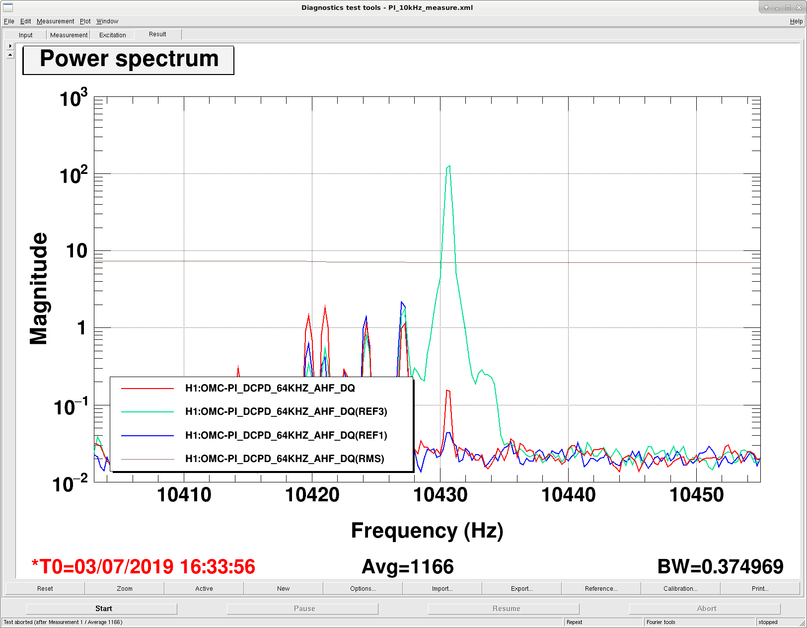
In the attached figure, the blue trace is about the OMC DC PD fast channel's baseline value when we're locked at 2W. The teal trace is as high as I rung the mode up to, and the red is where the mode was when we started the power up sequence on the way to NomLowNoise. So, I didn't let the mode ring all the way down, since we were starting to see similar ASC instabilities as we saw yesterday when we stayed at 2W for a long time. Not sure why we're getting this 0.54 Hz resonance in MICH, DHARD, and INP1 after an hour at 2W, but it is likely that we just don't have the ASC RF PD phases tuned to be happy at 2W or something.
Strange is that the RMS channel that monitors this PI mode doesn't seem to respond sensibly to the ring up and ring down of this PI mode. The RMS is just looking at the bandpass that is part of the damping loop that I'm using to ring up the mode, so it should be totally obvious and clear and we should see the RMS change. So, I don't yet have an answer for the Q value - I'll have to do some math and comment later today.
Updated which Glitch Gram webpage is displayed in the Control Room on nuc0 from Omicron back to DMT Omega. There had been an issue with DMT Omega so we had been using Omicron the last few weeks; we now have the "last hour" plot for DMT Omega up on the wall. nuc0 instructions have also been updated accordingly & I mentioned this to Carlos.
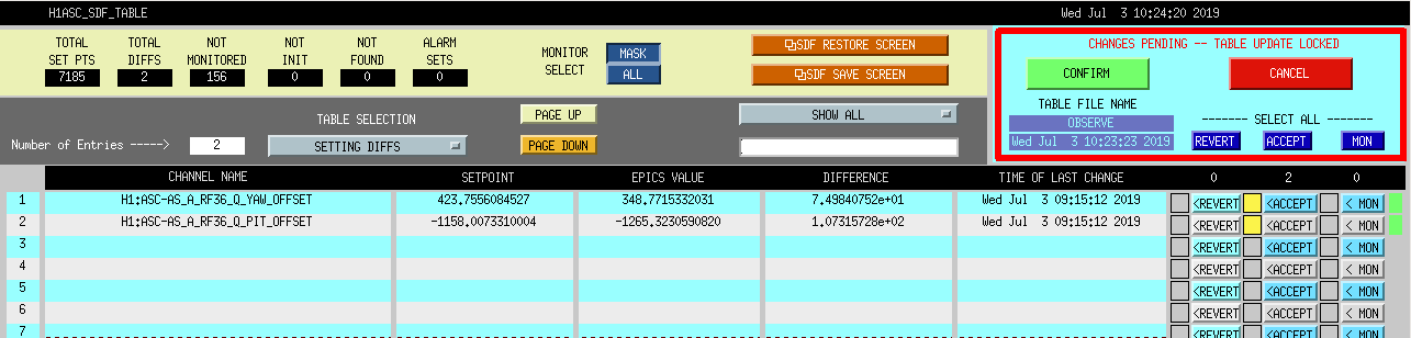
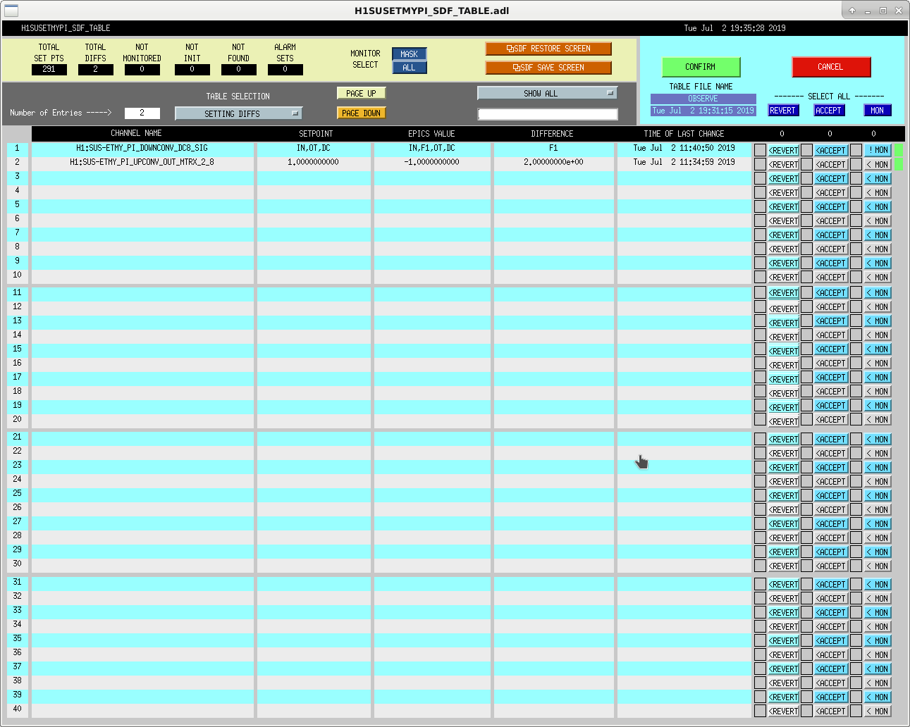
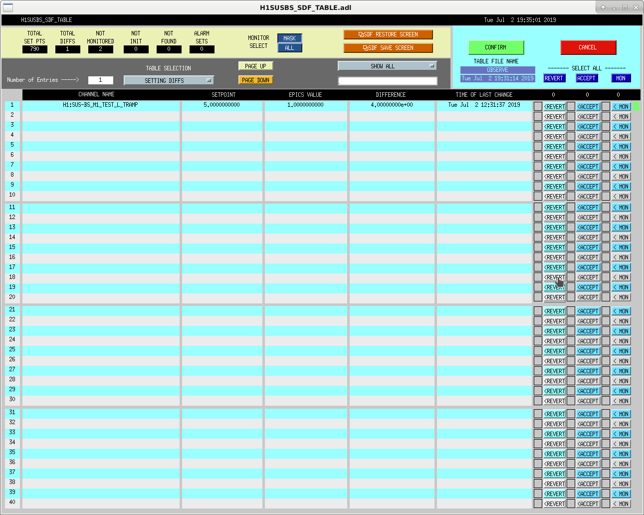
Back to Observing after a lock loss, initial alignment, quick PI measurement, and an SDF diff.
Topped off crystal chiller with 275mL of water (last fill was 3-weeks ago on 6/12/19). Diode chiller and filters were OK.
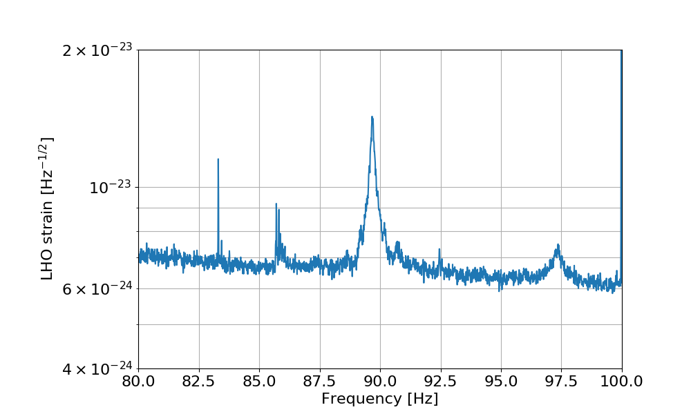
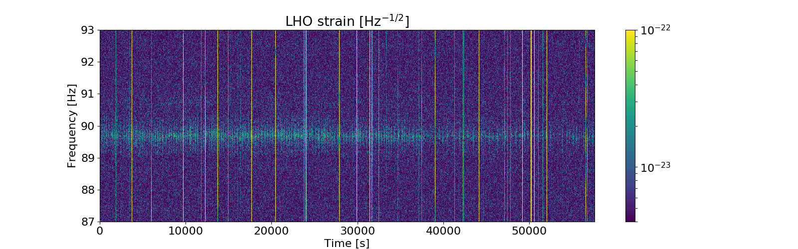
The bump at ~90 Hz is breathing with a very prominent periodicity of about 3 mHz. Any idea where this oscillation could come from?
The first plot shows a zoom around 90 Hz, where the bump is quite clear.
The second plot is a spectrogram of the same 16 hours of data (from 1245974418), showing the non-stationarity of the bump.
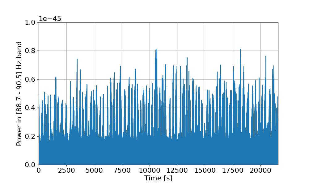
The third plot shows the band-limited RMS computed on the bump (between 88.7 and 90.5 Hz), with large glitches removed. The periodic "on and off" behavior is quite evident.
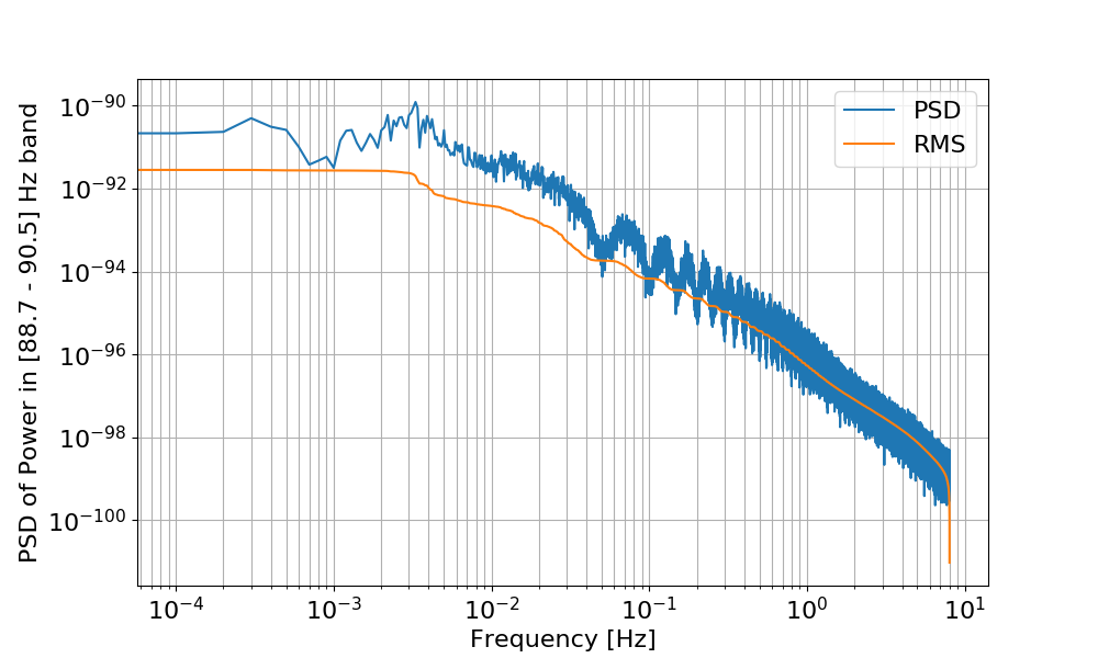
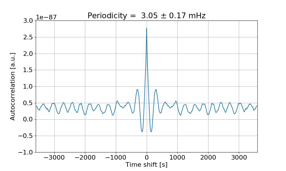
The fourth plot shows the PSD of the time series of the BLRMS, and the integrated RMS. There is a peak at 3 mHz. This is even more visible if one computes the autocorrelation of the BLRMS series: the fifth plot shows that the autocorrelation has a clear signature of a 3 mHz periodicity.
I decided to run an initial alignment because I could not keep the green arms locked, despite flashes > 1. I requested INITIAL_ALIGNMENT from ISC_LOCK and the entire process finished without me having to intervene. Yesterday, I had to touch green arms slightly, but this was the first time I didn't have to do anything.
The entire alignment took 22 min. (1523 - 1545 UTC)
TITLE: 07/03 Day Shift: 15:00-23:00 UTC (08:00-16:00 PST), all times posted in UTC
STATE of H1: Lock Acquisition
OUTGOING OPERATOR: Travis
CURRENT ENVIRONMENT:
Wind: 10mph Gusts, 7mph 5min avg
Primary useism: 0.03 μm/s
Secondary useism: 0.09 μm/s
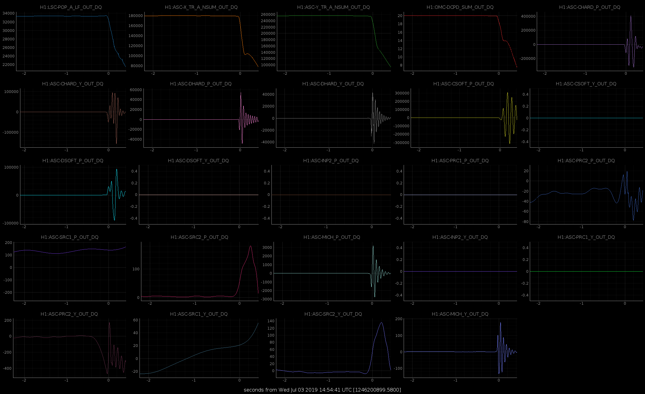
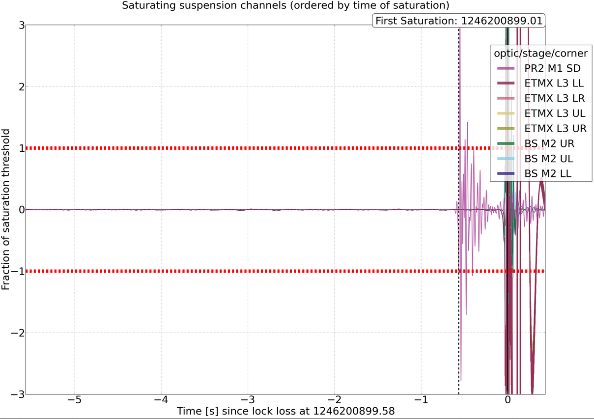
QUICK SUMMARY: Lock loss just as I arrived. No obvious reasons found yet.
TITLE: 07/03 Owl Shift: 07:00-15:00 UTC (00:00-08:00 PST), all times posted in UTC
STATE of H1: Observing at 116Mpc
INCOMING OPERATOR: TJ
SHIFT SUMMARY: Another quiet shift. One GRB alert. Lockloss at the very end of shift.
LOG: Previous aLogs.
Seemingly spontaneous lockloss. Environment is calm. No indication of cause. Sorry TJ!
GraceDB UID E337636.
Fermi alert trigger num 583854113.
Trigger duration of 0.016 second.
Beginning stand down time.
I just realized that the Observatory Mode had not been changed since Jim relocked before the start of my shift. I changed it to Observing at 8:48 UTC, but it should have been changed closer to 6:22 UTC. Can this be retroactively changed for time reporting?
Thanks for noting, Travis. I am not sure we can change this (or if we can, it is not trivial). So the times you note will be helpful for analysis/notes later.
TITLE: 07/03 Owl Shift: 07:00-15:00 UTC (00:00-08:00 PST), all times posted in UTC
STATE of H1: Lock Acquisition
OUTGOING OPERATOR: Jim
CURRENT ENVIRONMENT:
Wind: 8mph Gusts, 7mph 5min avg
Primary useism: 0.02 μm/s
Secondary useism: 0.07 μm/s
QUICK SUMMARY: Lock is ~1 hour old. Range is 116 MPc. Nothing out of the ordinary to report.
Can't include the normal header because Chrome isn't playing with the HTML editor for the alog. Travis is taking over, we're observing, range is normal. 2:30 Observing after struggling with wind and doing an initial alignment 4:53 A 5.3 eq in north Alaska breaks the lock I didn't get a chance to change SEI states 6:30 I noticed asc and a couple other signals were doing decidedly earthquake like things, so I switch to the EQ state. This was a 4.3 in Mexico that was barely off the board on the sei eq plot, and ended up not a big deal, but hard to know beforehand. 6:41 SEI back to windy
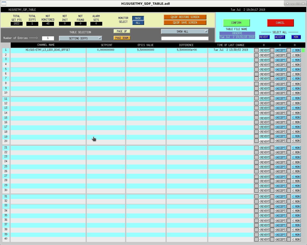
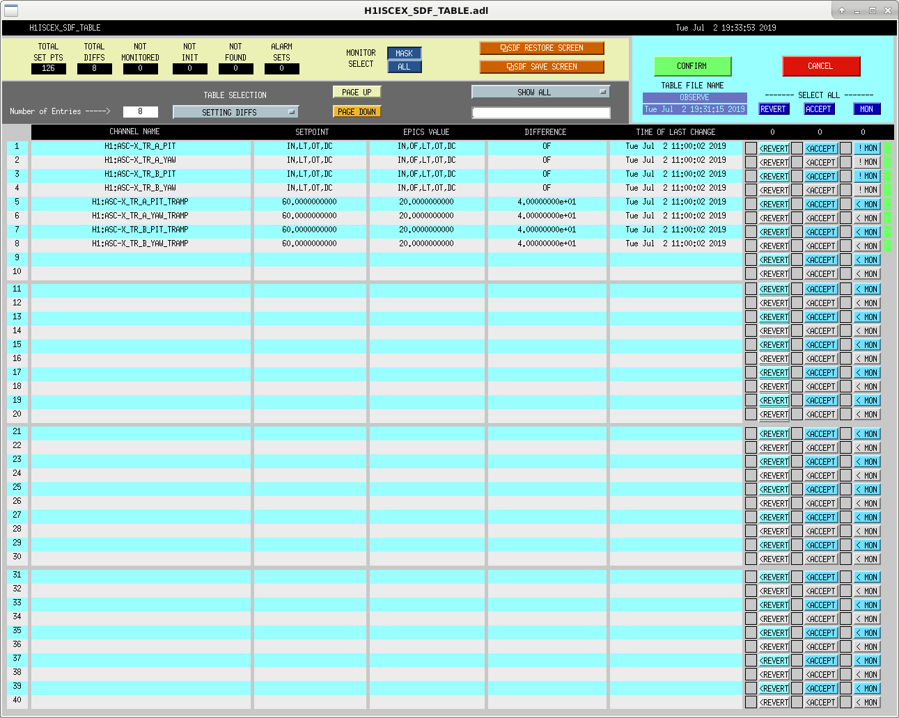
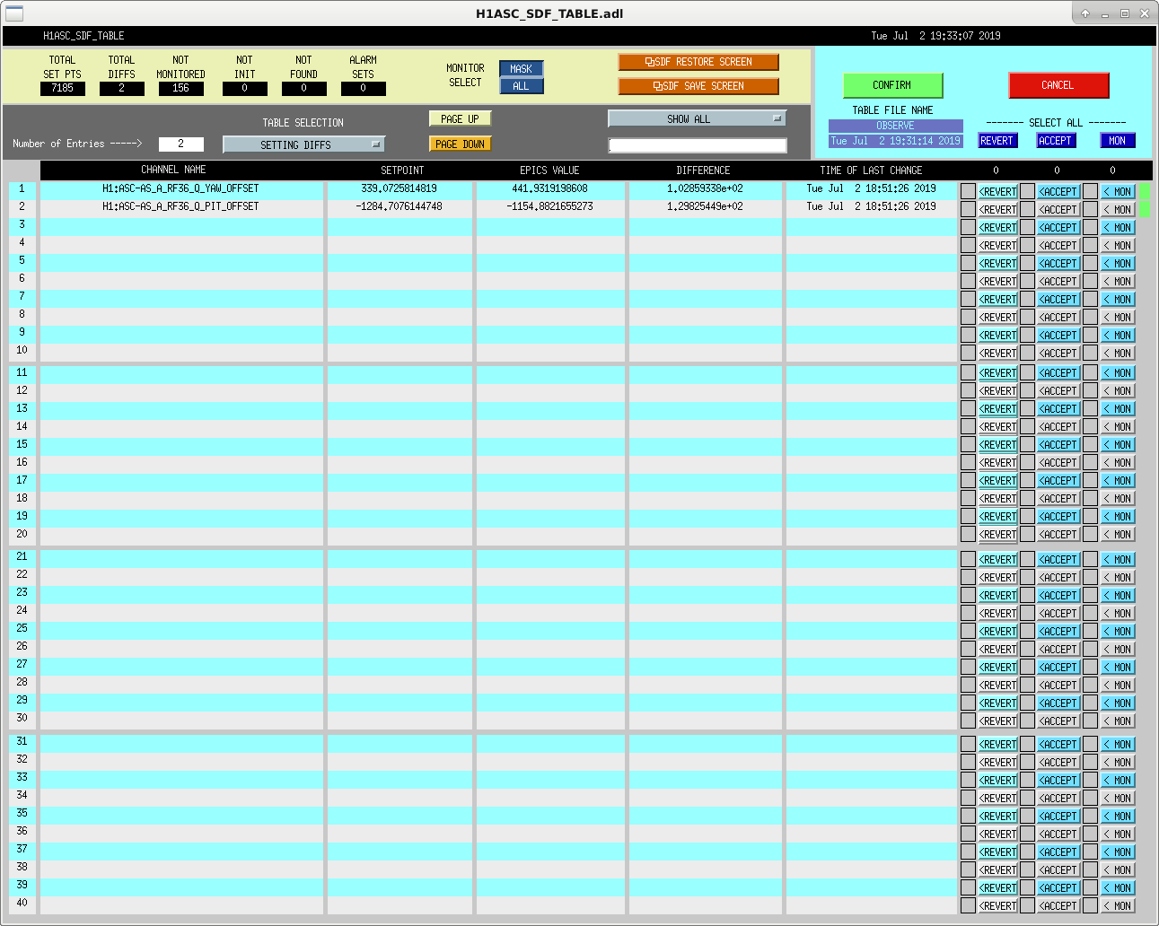
Finally back to low noise after struggles with wind, ALS and ASC. Bunch of SDF diffs, some of which I think are left over from the commissioning work earlier?
Shoot, sorry.
I was wrong on the ETMY ESD bias - Jim checked and found that there was no value in the offset, just the button was on. So, no impact at all on DARM.