The satellite amplifiers for FC1 and FC2 were swapped out on August 5, 2025 (86207). I checked the filter cavity LSC and ASC signals to see if we can see improvement in the noise before vs after the swap.
For the LSC signals, I looked at H1:SQZ-FC_LSC_DOF2_OUT_DQ, since that is the LSC channel that is on when we are fully locked.
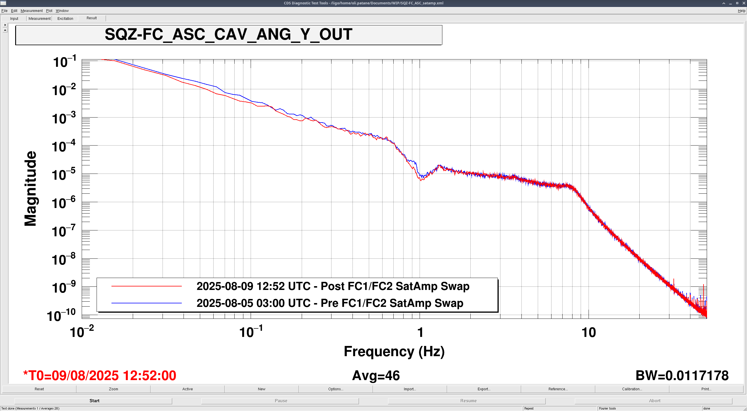
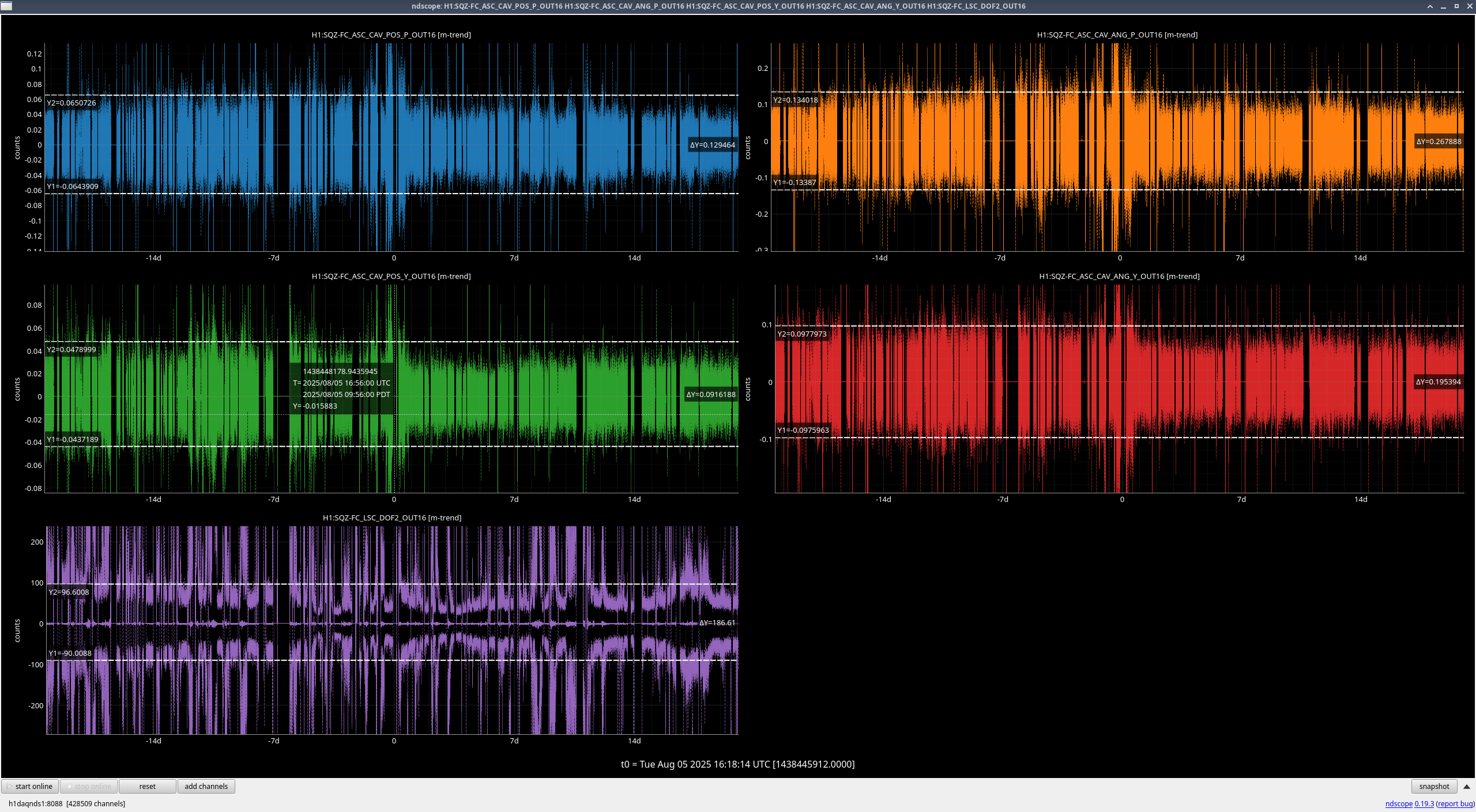
For the ASC signals, I looked at H1:SQZ-FC_ASC_CAV_{POS,ANG}_{P,Y}_OUT_DQ, since those are the ASC signals inside the filter cavity.
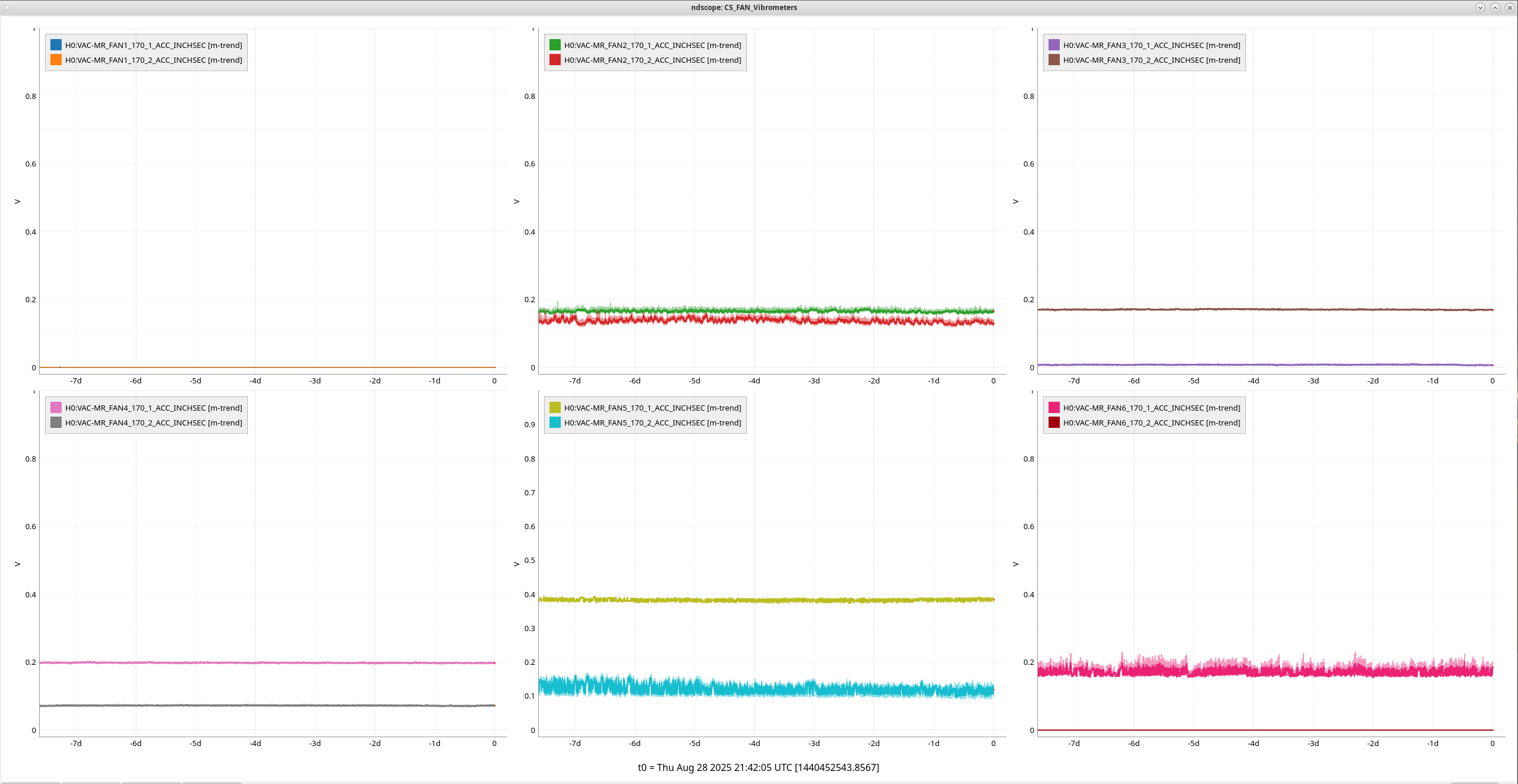
Even just looking at the ndscope of the average noise levels of these channels before and after the satamp swap (swap at t=0), all the ASC channels seem to drop a bit in noise after the swap. It's hard to tell anything from the LSC DOF2 channel.
For comparing spectra, I looked in the range of a few days before and a few days after the swap and found before and after periods of 50 minutes each where the ASC noise looked to be at its lowest. These times and their measurement settings were:
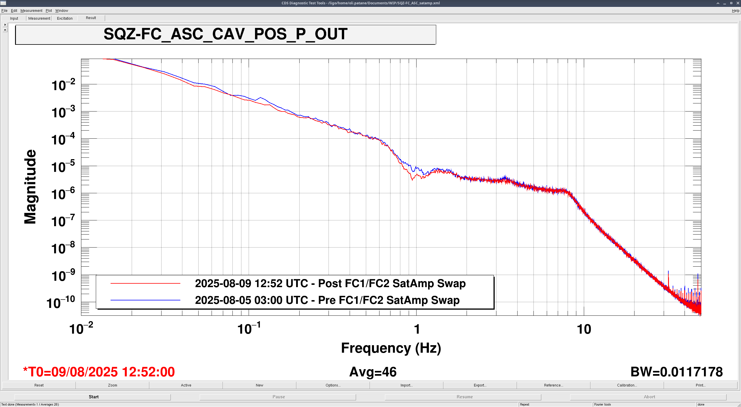
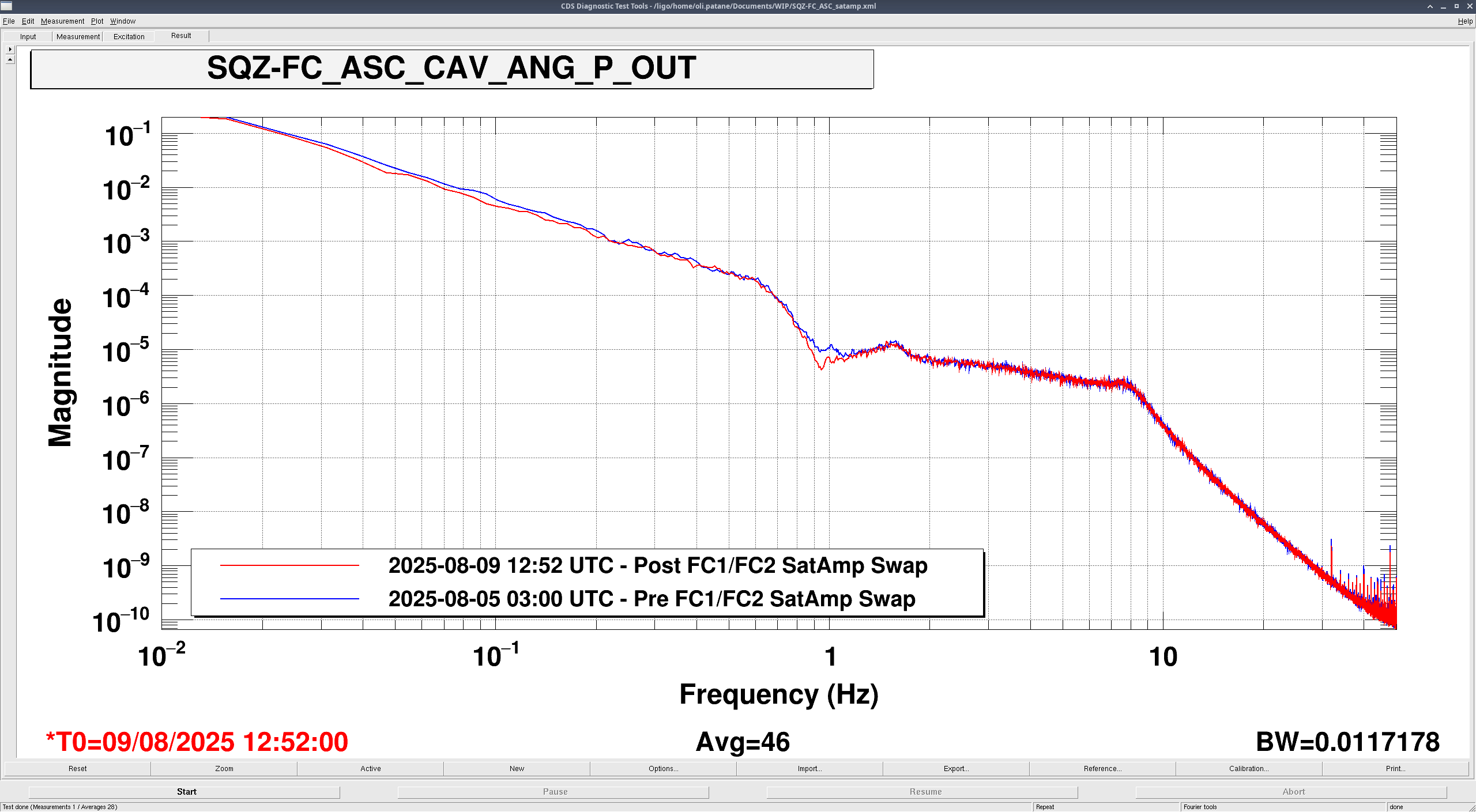
Before: 2025-08-05 03:00 UTC; 0.01 BW, 46 averages (BLUE)
- Bonus Before for SQZ-FC_LSC_DOF2_OUT_DQ: 2025-08-02 09:23 UTC; 0.01 BW, 46 averages (GREEN)
After: 2025-08-09 12:52 UTC; 0.01 BW, 46 averages (RED)
I also tried out a couple other before times, trying to get the absolute lowest noise before the satellite amplifier swaps, but this before time had the lowest noise that I could find. The bonus Before time for LSC DOF2 is because I was able to find a time where the noise below 0.6 Hz was decently lower than the noise from the default Before time.
Comparison results
ASC
Pitch
SQZ-ASC_CAV_POS_P_OUT_DQ
SQZ-ASC_CAV_ANG_P_OUT_DQ
Yaw
SQZ-ASC_CAV_POS_P_OUT_DQ
SQZ-ASC_CAV_ANG_Y_OUT_DQ
Most of the improvement is seen around 1 Hz, which looks really good!
LSC
SQZ-FC_LSC_DOF2_OUT_DQ
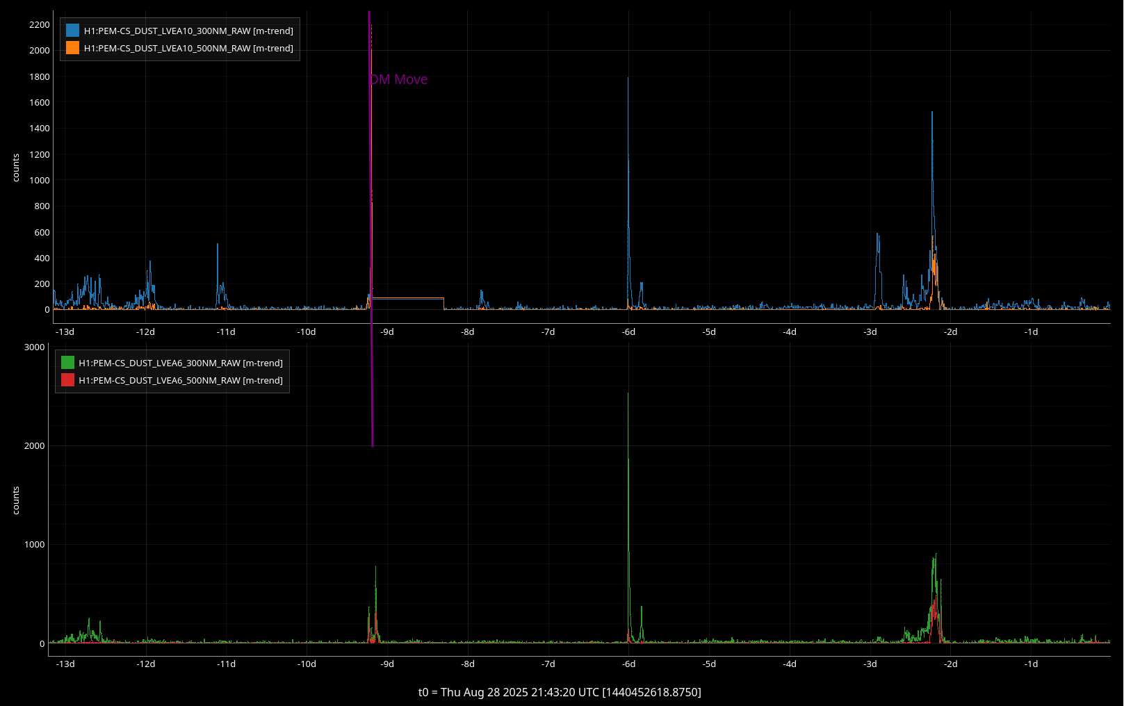
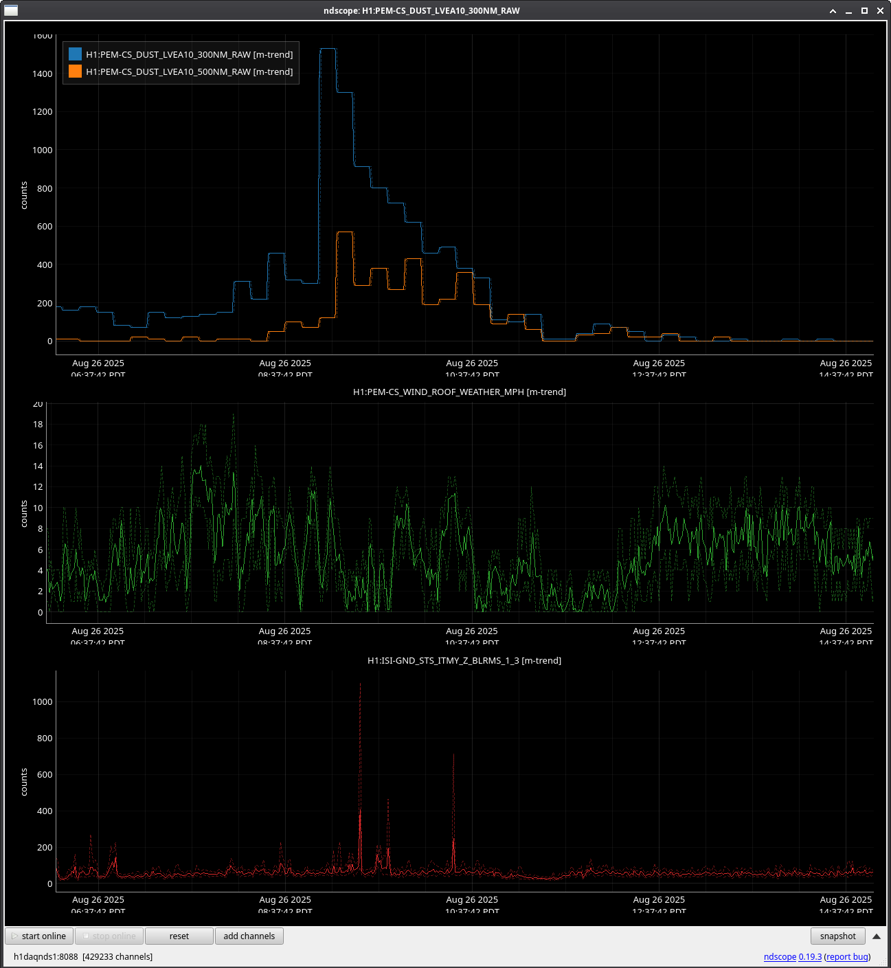
When only comparing to the default Aug 05 03:00 UTC (BLUE) before time, we see broadband improvement almost everywhere below 3.5 Hz. When comparing to the bonus before time (Aug 2 09:23 UTC), however, it looks like the noise between 0.3-0.55 Hz is much better before. I believe this is due to lower ground motion at the time of the green before time (ndscope).