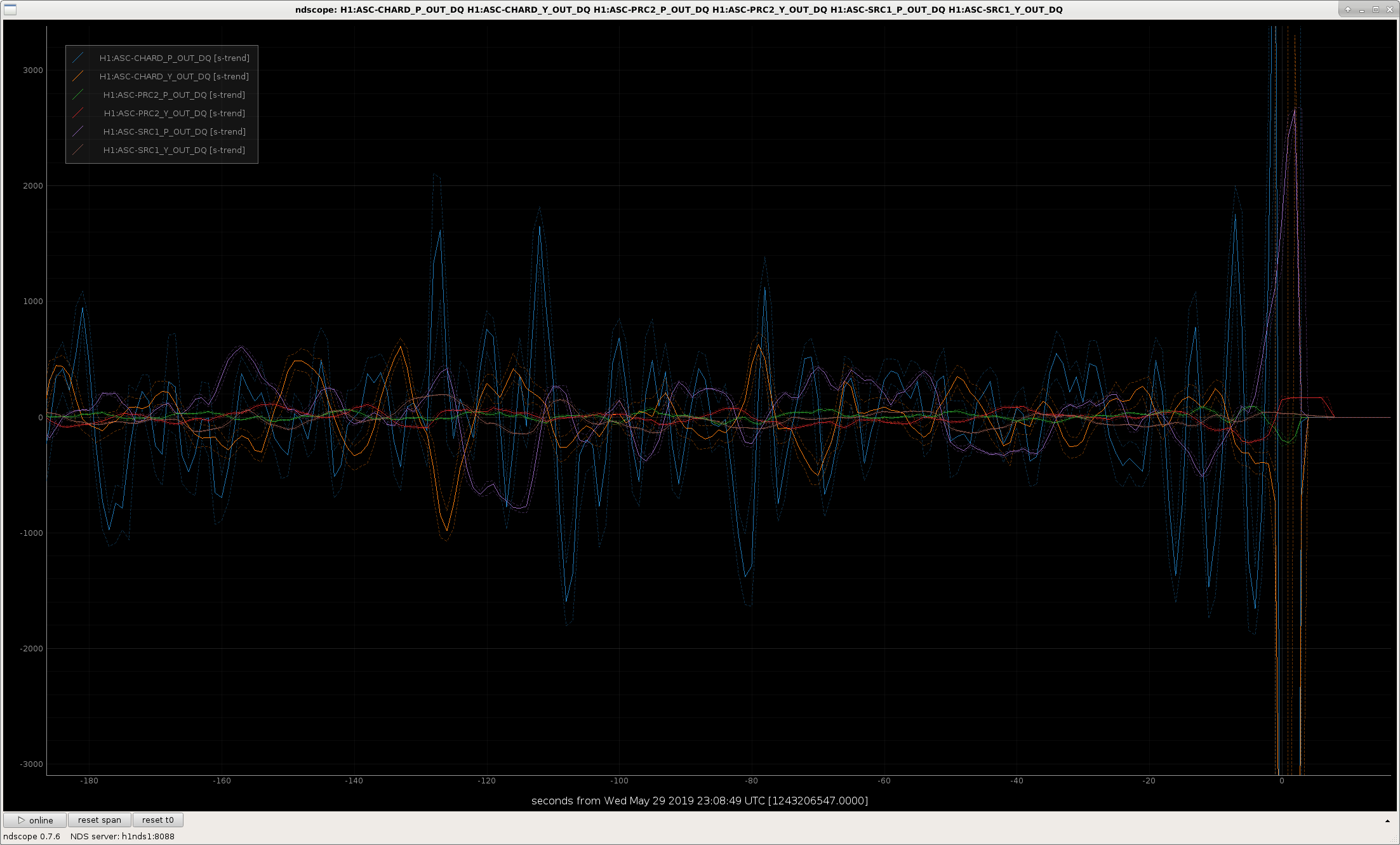
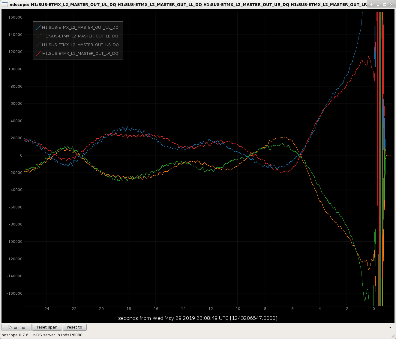
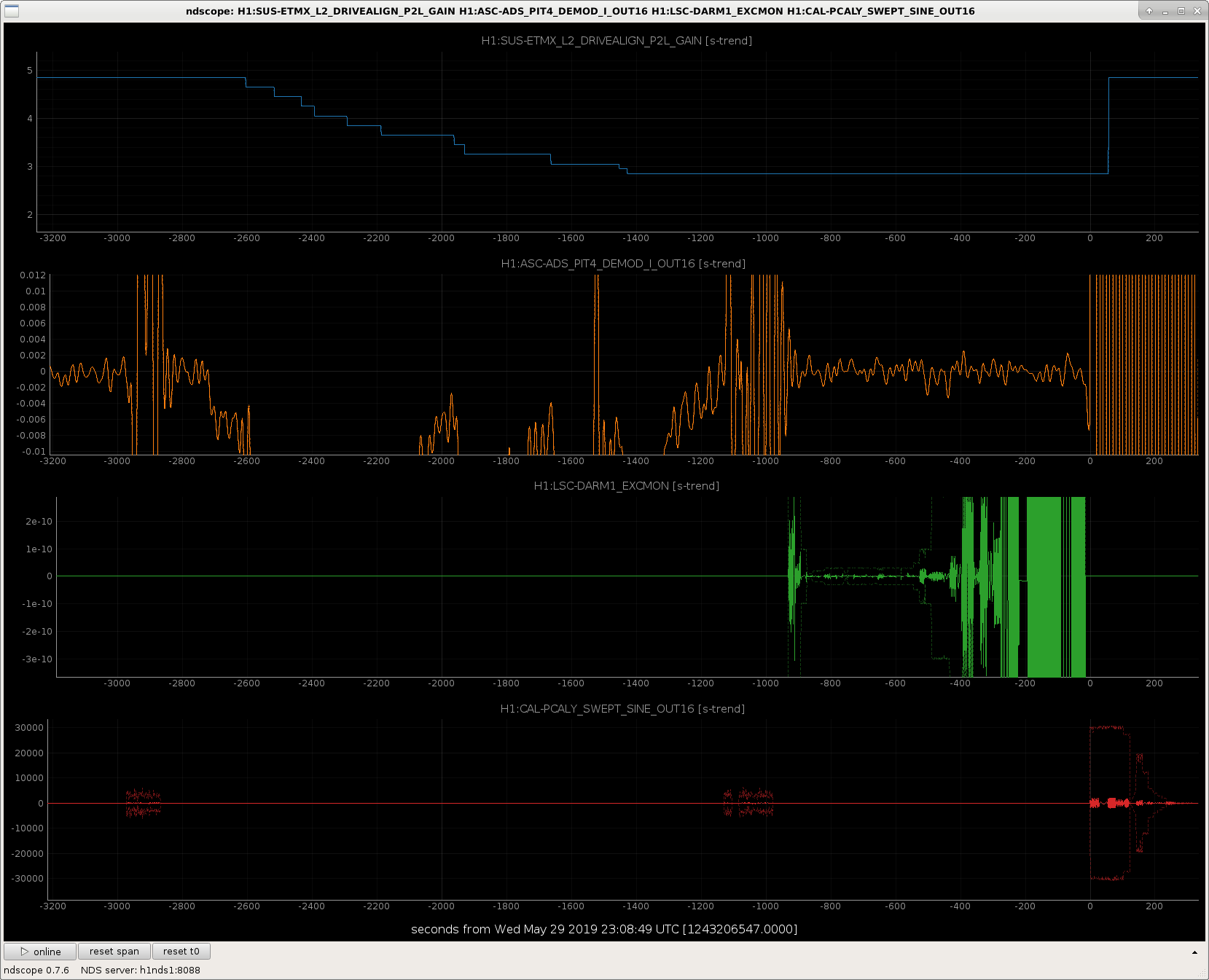
J. Driggers, J. Kissel, S. Dwyer We were unsuccessful at measuring the two things we needed in yesterday's attempt (LHO aLOG 49541) at checking whether the ETMX IFO beam's spot position (i.e. determined by ETMX PUM A2L gains) impacts the sensing function measurement [where the hypothesis is that the confusing, apparently a-causal detuned spring response -- see e.g. LHO aLOG 48083 -- is an artifact of the DARM EXC through all stages of ETMX (including the PUM, which we suspect has L2A2L problems because of the spot position) during the open loop gain transfer function half of the two-part sensing function measurement suite]. Here "unsuccessful" means that we were able to get one half of the measurement -- the swept-sine DARM Open Loop Gain TF, but apparently lost like right at the start of the swept PCAL2DARM transfer function. However, upon further investigation (details below), we believe the lockloss was NOT caused by starting the PCAL excitation, but by a rather fast run-away (within 5 seconds) of the SRC1 Pitch loop which in turn cross-coupled to the ARM ASC DOFs, and saturated ETMX. This is after ~1000 seconds of being happy in the moved-spot configuration. As such, we suggest the following when we try again: (1) Pay closer attention to the SRC1 P loop: (a) either rephase the AS72 WFS after spots have moved, or (b) open the SRC1 P loop during the measurement, and (2) Be faster with the measurement. (2) will be a challenge, given that -- assuming all things the same, we'll only have ~1000 secs, and we *need* a swept sign measurement downs to ~5 Hz in order to really resolve changes in the funky detuned spring. Our suggestion is to lop off data above ~100 Hz, and maybe relax the integration time by a factor of 2. But at least we now have a path forward to try again. Investigation Details: (1) I ran "lockloss select" in a terminal, and selected the appropriate lockloss time from the list. This opened the lockloss tool webpage for GPS time 1243206548. (2) Browsing through the signals, at the 30 sec and 5 sec prior to lock loss, we immediate saw three suspicious things: (a) The ETMX L2 UL and UR (i.e. the PUM stage of ETMX) was the first to saturate, and did so in a rather sudden, but still slow (~5 sec time scale) and in a "runaway" fashion, not in a "oscillation" fashion, nor in a "sudden huge burst." Because the PUM is involved, which is the only stage the ASC system uses for control, this puts ASC signals rather high on the suspect list. (b) Scrolling down to the ASC section, we find the CHARD P, (and the remaining arm DOFS in P) show a 0.15 Hz oscillation, which apparently ramps up within the last 5 seconds, and (c) SRC1 P shows an interesting "runaway" feature that looks similar to the ETMX saturation. (3) Upon pulling up these channels in NDSSCOPE -- such that we can investigate the time scale, whether these 30 seconds was similar to the previous many minutes that we had been stably functional in the spot, and to confirm that it wasn't the PCAL measurement's fault -- we confirm that (a) The PCAL excitation had started *extremely coincidentally* with the lock loss, but was not the cause. The DARM OLGTF excitation had stopped at 15 seconds before the lock loss, and the PCAL measurement start 1 second after. Neither correlated with the sudden change in character of the ASC signals 5 seconds prior. (b) The spot position, driven by the ADS system and triggered by the change in ETMX PUM P2L gain change, had settled (the ADS signal had converged), by ~1000 seconds before the lock loss, so the ~5 sec time-scale of the last-minute runaway or oscillations is not a function of the new spot position. (c) The apparent runaway "oscillation" of arm ASC DOFs, and specifically CHARD is a selection bias -- these kind of 0.15 Hz periodic wiggle in the last 5 seconds of the lock are at roughly the same amplitude as similar wiggles within the past ~1000 seconds when we arrive at the new spot position. From this, we conclude that the SRC1 P runaway was the cause of the lock loss. Thus, we should NOT need to bother to adjust any ASC loop gains, because the lockloss was NOT caused by loop oscillating. We also don't need to worry about running the same templates for the CAL measurements. Thus we suggest the above ideas for trying again.
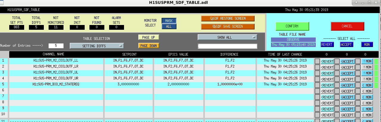
Accepting the following sdf differences to SUSPRM. Sheila noted that the values we are accepting match the values that were being used during the previous lock, so it seems that the SUSPRM setpoints might be changing unexpectedly between losing lock and reaching NLN.
Jenne, Georgia, Sheila
Lockloss while trying to AC couple ISS:1243269492
~ 2 hours to relock because of other relocking issues:
1 attempt at increasing input power: We requested 38W but the rotation stage calibration was off so we got 40W out of the PSL. Things seemed OK, Georgia tried to increase CO2X. We checked the REFL wfs phases with a frequency noise injection, they seemed OK. While we were attempting to measure an ASC sensing matrix for the REFL WFS, we noticed that the ADS YAW3 (ITMY to PRM dither loop) was running away, and something started to become unstable. We powered down to 35W out of the PSL, where we checked the phasing of ADS YAW3 which looks fine at 35W. We turned the loop back on and it seems OK here, so this is something that we need to investigate more.
We went back to low noise at about noon. Georgia is now investigating why the ISS AC coupling was a problem.
Laurence Datrier, Sheila Dwyer
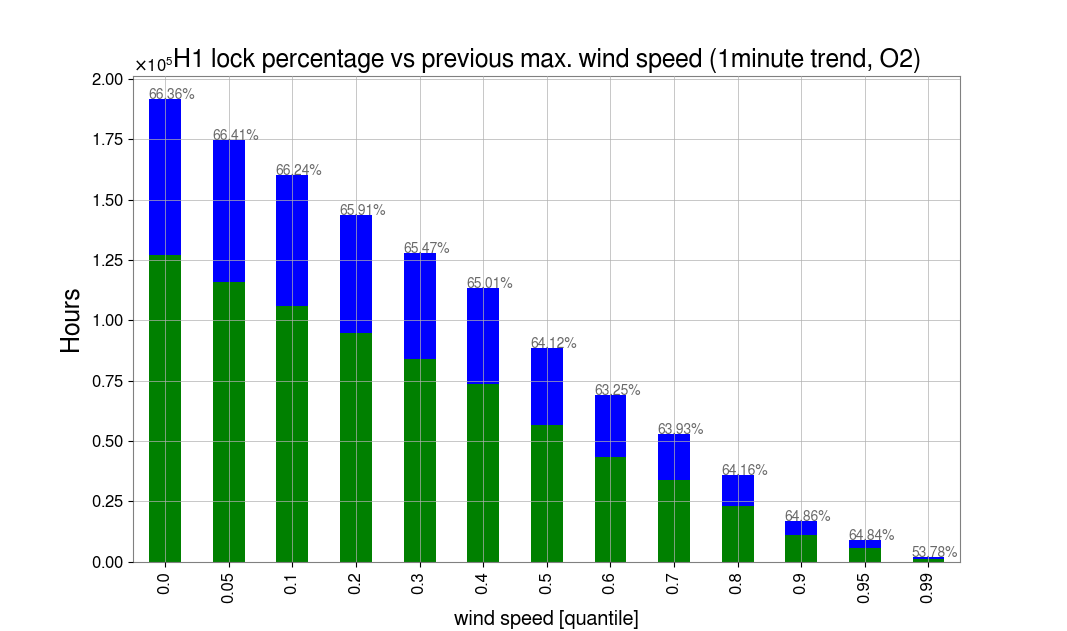
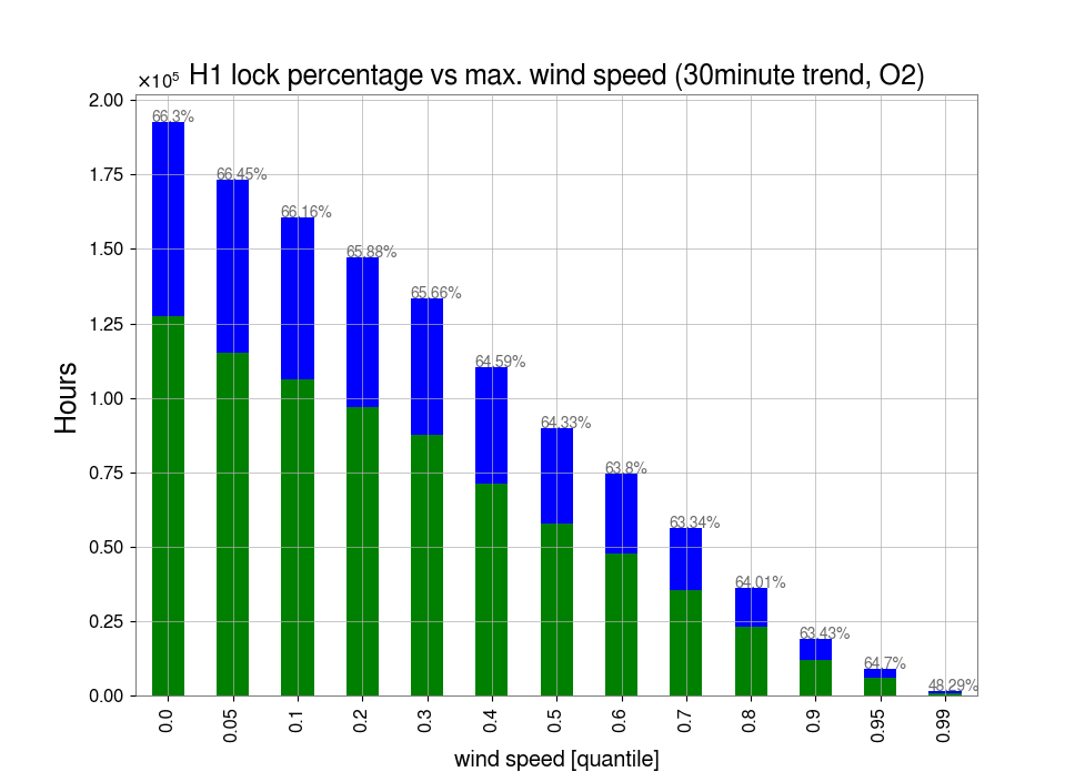
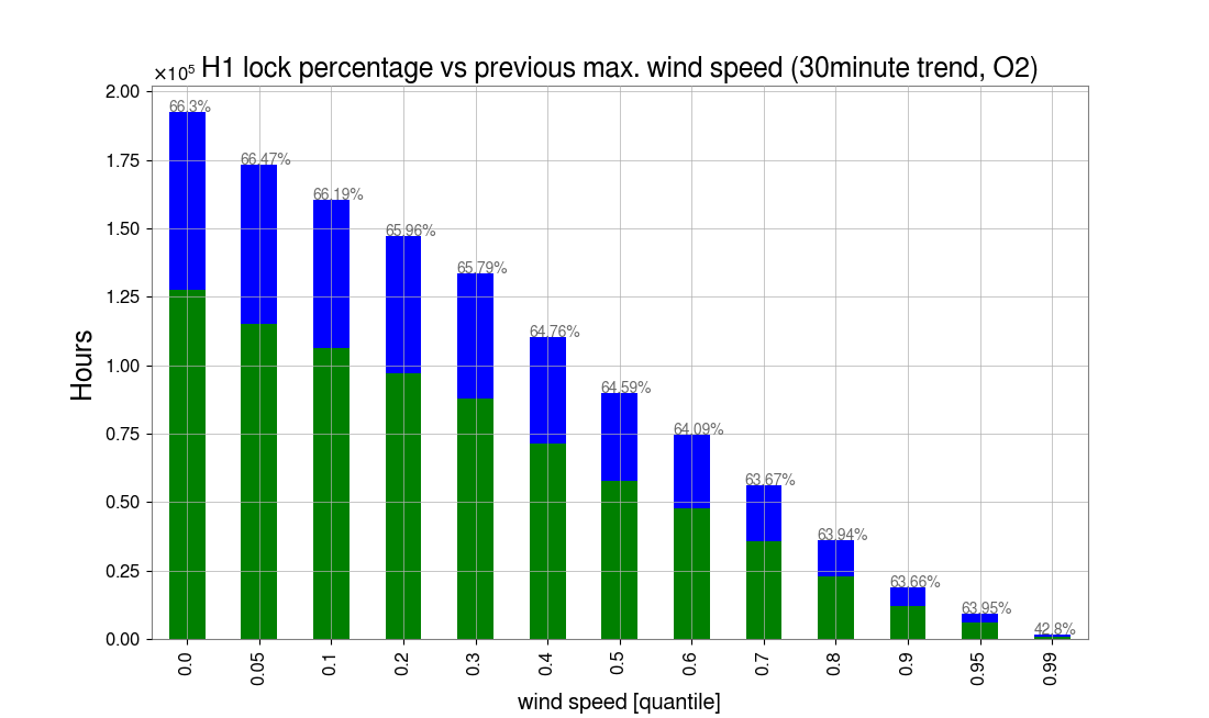
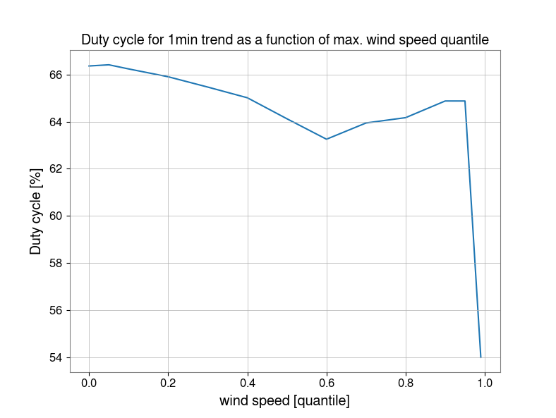
We looked at O2 data for H1 to get an estimate of down time due to wind. We used the maximum wind speed of the three max. 1min and 30min trends for the H1 EX, EY, CS wind channels, for all of O2.
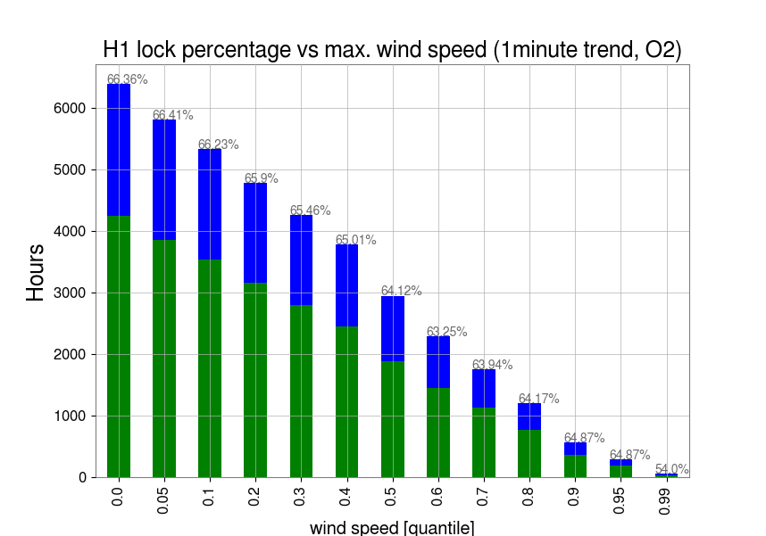
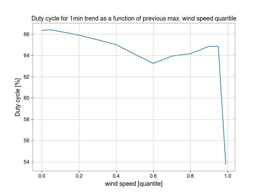
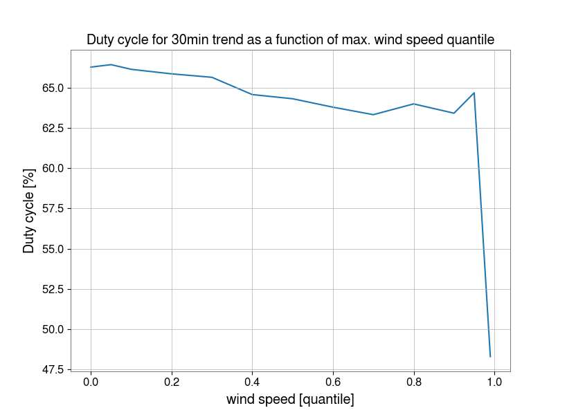
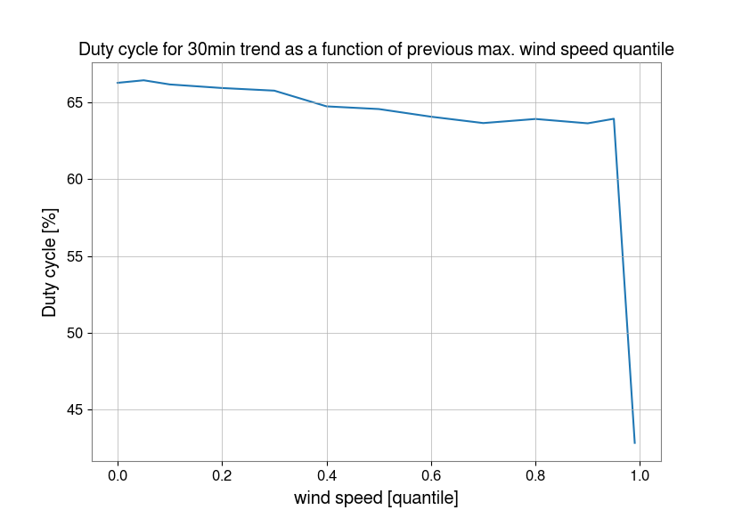
The first histograms and trend line show duty cycle vs wind speed percentiles, for wind speed vs lock status and previous wind speed (max. of previous 1 or 30 min) vs lock status. Looking at the previous wind speed shows more down time due to high winds. Percentiles and wind speed values are (in mph):
| percentile | 5 | 10 | 20 | 30 | 40 | 50 | 60 | 70 | 80 | 90 | 95 | 99 |
| 1min trend wind speed [mph] | 3 | 4 | 5 | 6 | 7 | 9 | 11 | 13 | 16 | 21 | 25 | 33 |
| 30min trend wind speed [mph] | 5 | 6 | 7 | 8 | 10 | 12 | 14 | 17 | 21 | 26 | 31 | 41 |
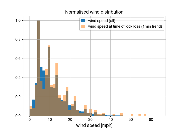
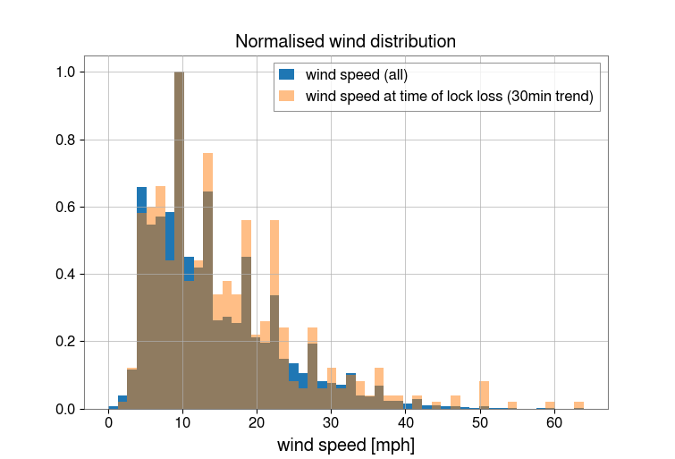
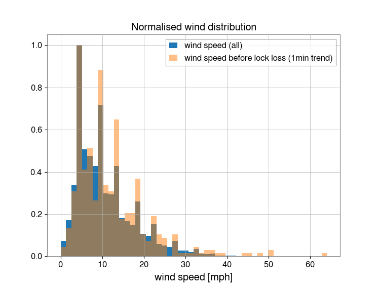
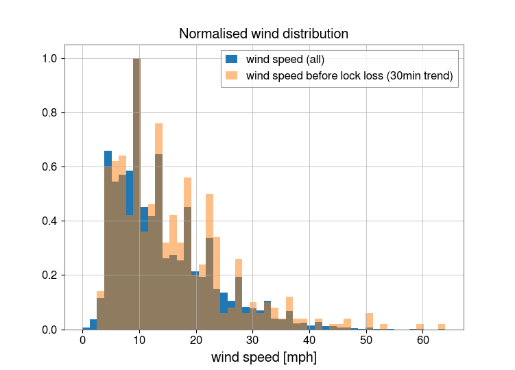
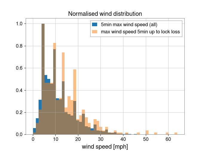
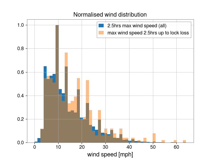
The following histograms are the normalised distributions for wind speed at:
Compared to the normalised distribution at all times (blue). A significant tail appears in the distribution for wind speed at time of lock loss for winds >~35mph.
Interesting. Is this consistent with the histogram of 8 years of wind speed data in this log:
https://alog.ligo-wa.caltech.edu/aLOG/index.php?callRep=12996
and the O2 locking vs wind speed in Figure 16 of this paper?
https://dcc.ligo.org/LIGO-P1800038
It would also be useful to calculate the correlation of BNS range with wind speed. We may be able to maintain lock at higher wind speeds than in the past, but does the range suffer?
I used the wind wind speed histogram from 8 years of data at LHO:
https://alog.ligo-wa.caltech.edu/aLOG/index.php?callRep=12996
to calculate a wind probability density function. I then convolved it with a fit (approximation) of the O2 duty cycle vs wind speed from figure 16 in:
https://dcc.ligo.org/LIGO-P1800038
If interferometer locking was completely independent of wind speed, then only a 1.6% improvement in duty cycle would result.
However the BNS & BBH range *may* decrease at higher wind speeds.
Based on the table that Laurence posted, these wind speed percentiles are fairly consistent with Margarita's 8 year histograms in 12996. Margarita finds that the hourly maximum of the wind speed is about 31.3 mph 4.8% of the time, Laurence finds that the 30 minute maximum exceeds 31 mph 5% of the time.
Note that Laurence is plotting duty cycle for all the times with wind speeds above a certain quantile, while Krishna plots duty cycle vs wind speed in P1800038 , so they aren't directly comparable. The best comparison to Figure 16 would be to Laurence's 5th attachment, which is quite similar, the duty cycle is between 60-70% for wind speeds less than ~32 mph in P1800038, and less than the 99th percentile for the minute trend in Laurence's plot, which is 33mph.
I believe that the duty cycle vs wind speed plot in Figure 16 of P1800038 is based on minute trends of the wind speed, although I'm not completely certain of that. If it is based on minute trends, it makes most sense to convolve the wind speed vs duty cycle plot from P1800038 with a wind speed distribution based on the first line in Laurence's table, based on minute trends. (Or, to use wind speed vs duty cycle based on hour maximum instead).
The detailed O2 time accounting for H1 states that the interferometer was only down for wind 0.3% of the time:
https://ldas-jobs.ligo.caltech.edu/~detchar/summary/1164556817-1187733618/time_accounting/lho/
As Daniel point outs, wind might be responsible for some fraction of the time spent trying to re-lock.
Curiously the O2 accounting for L1 states that wind caused 2.7% downtime:
https://ldas-jobs.ligo.caltech.edu/~detchar/summary/1164556817-1187733618/time_accounting/llo/
I think it would be useful to run this again for O3 so far. A quick look indicates that the detector is rather more sensitive to wind now than at the end of O2. I went poking though the DetChar pages looking for impact of high wind - and one can see that for speeds of ~10 meters/sec one can often see dips in the range, and when the speed passes that LHO often looses lock. I counted up 15 days in the first 2 months where there seemed to be a clear correlation-by-eye between (wind vs. range) or (wind vs. operation). I expect there are many reasons why the detector is more sensitive, and hopefully we can get back to the sort of robustness that was achieved at the end of O2, but I think that, were there a wind break in place now, things would be easier to run.
I've posted an alog for the same analysis for O3, along with a look at the BNS range as a function of wind speed.
The Xarm green WFS were struggling a bit during re-acquisition this morning, so Sheila tried enabling the TMS WFS as well as the usual ETM WFS in the LOCKING_ARMS_GREEN state. This worked well, and she has previously also had it work for the Yarm, and has made a guardian state to do this in the ALS_ARMs.
I have now changed the ALS_ARM guardians to use the 2 WFS version (ETM and TMS) in the main path, and the ETM-only version is now on the side branch. This also required a change in ISC_LOCK guardian to request the 2 WFS state.
So far, we're still on the first acquisition with both green arms using both ETM and TMS WFS automatically through the guardian, but it seems to be working so far.
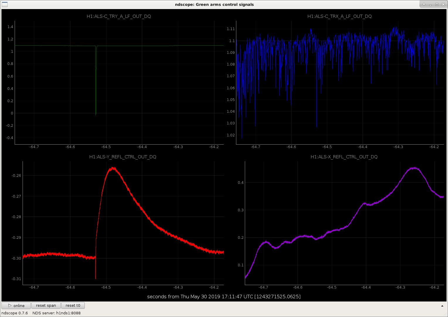
While trying to relock after loosing lock due to AC coupling the ISS, we had a re-occurance of the "rainy day" glitches which were addressed by burying the ALS Y arm fiber. 1243271468
Just noting this because we hadn't noticed them recently. It is not rainy right now.
Range is actually closer to 110 Mpc
Tagging @DetChar and SEI for data in seismic's sensor correction configuration transition studies.
Ops Shift Transition: 05/30/2019, Day Shift 15:00 – 23:00 (08:00-16:00) - UTC (PT)
State of H1: Locked
Intent Bit: Observing
Weather: Low wind, overcast
Primary 0.03 – 0.1Hz: 0.01 um/s
Secondary 0.1 – 0.3Hz: 0.1 um/s
Outgoing Operator: Jeff
Quick Summary: Locked for ~3 hours, Observing for 2.5. SQZ MANAGER has a notification that I haven’t seen before, but it doesn’t seem to be affecting range.
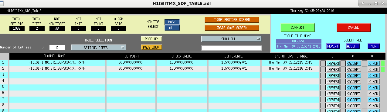
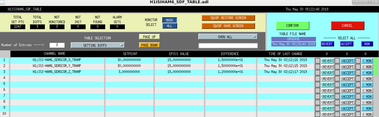
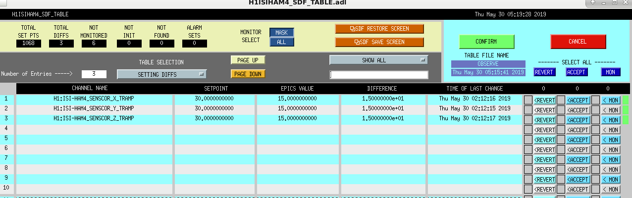
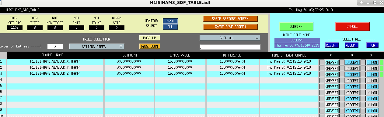
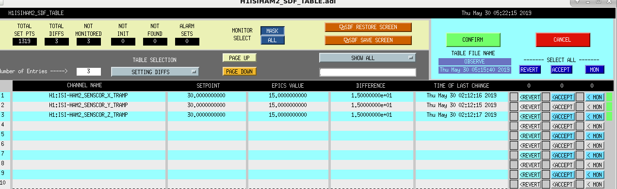
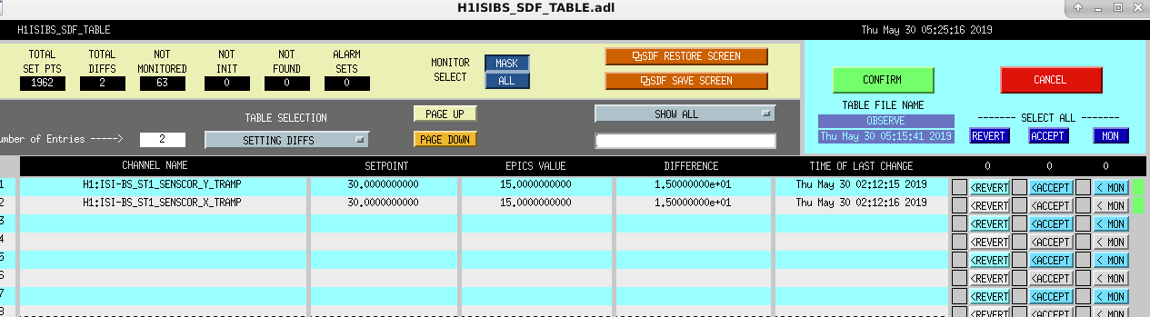
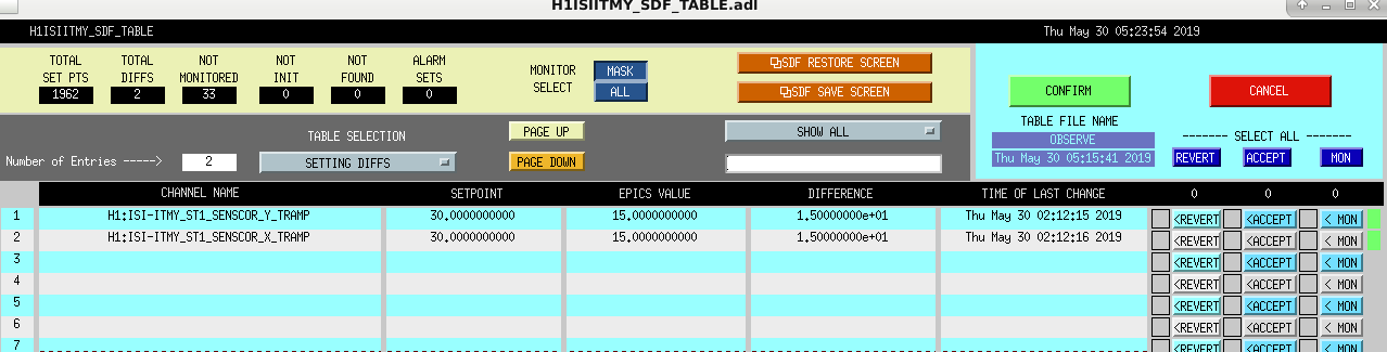
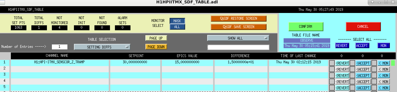
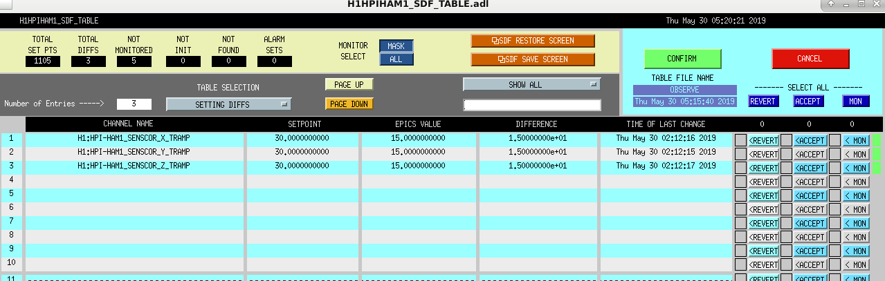
Accepted the following SDF differences upon relocking after the El Salvador earthquake.
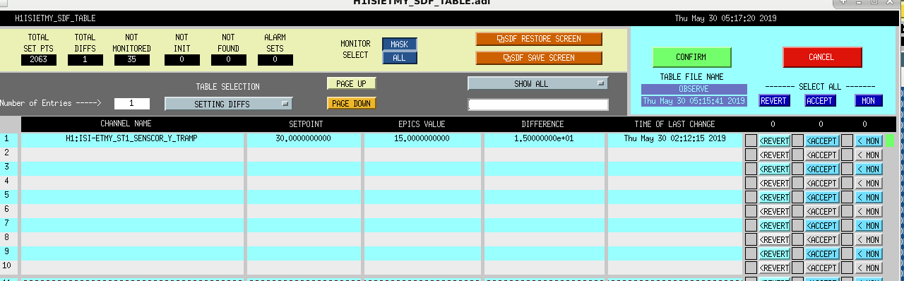
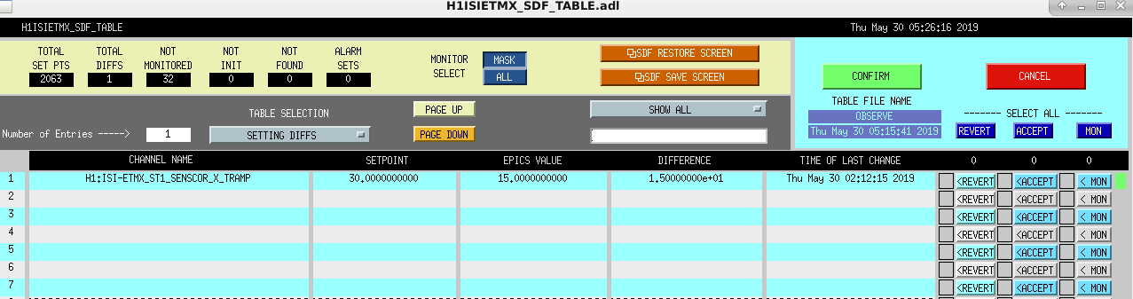
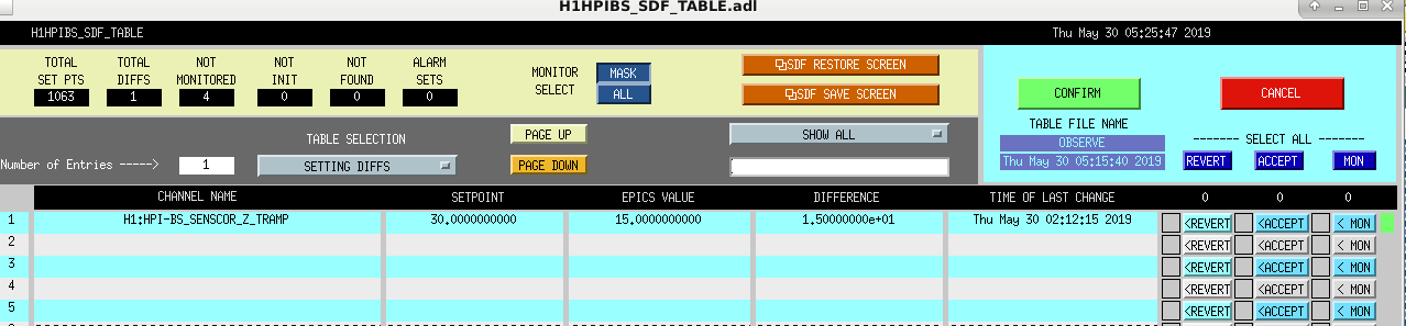
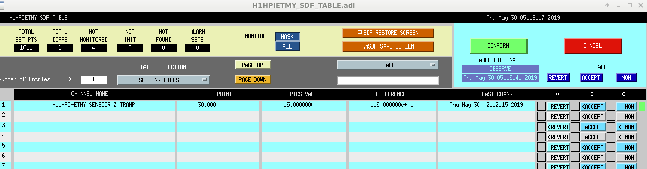
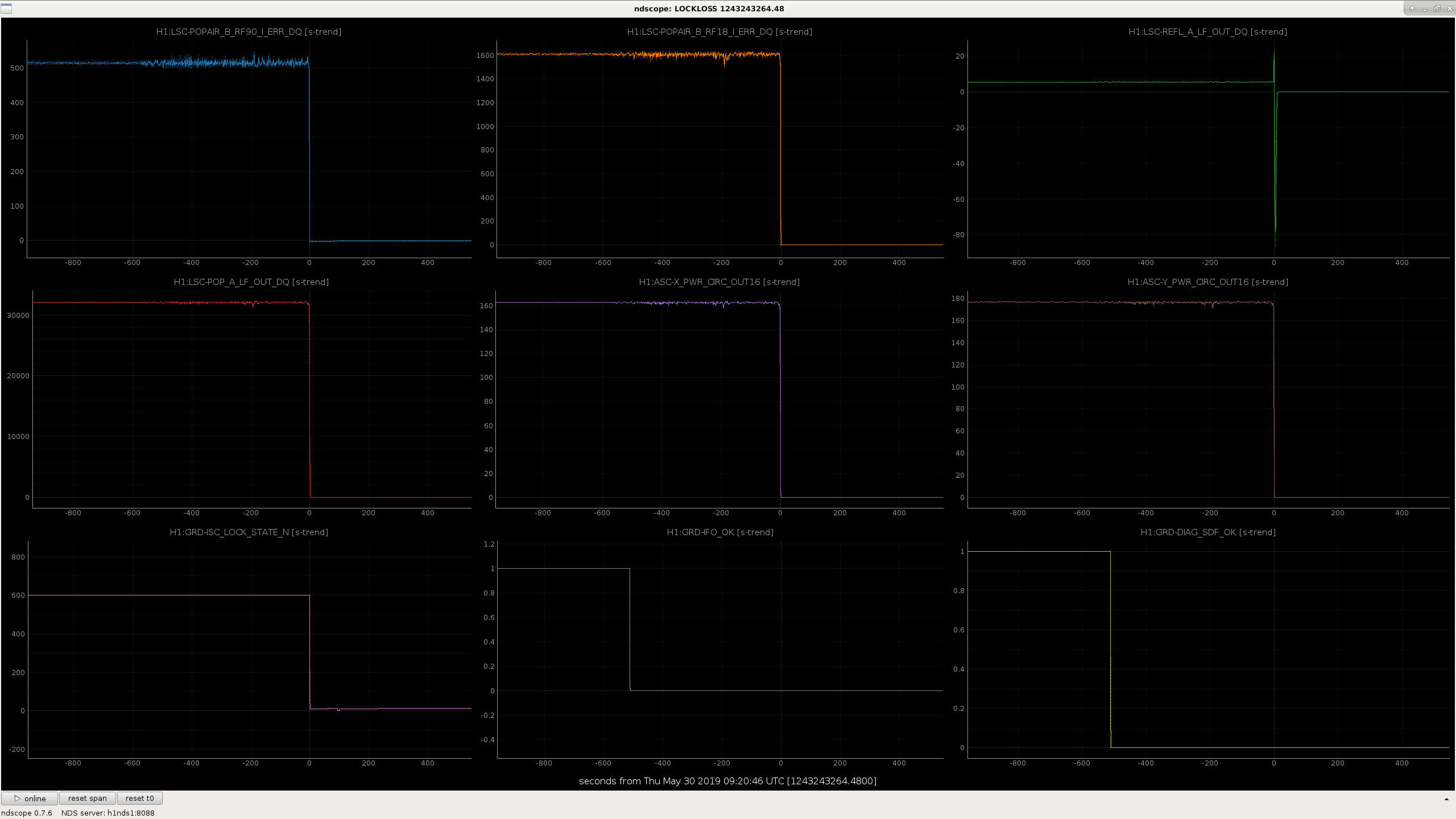
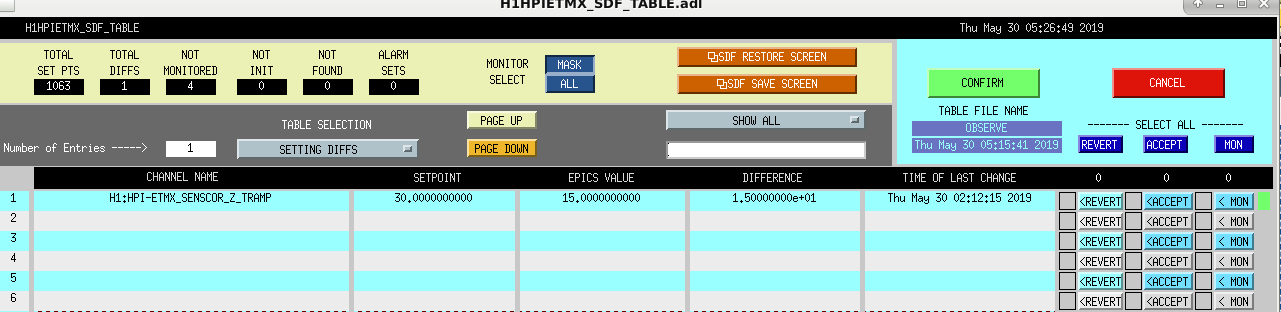
In the lockloss before this, 1243243265 Jeff tried to transition the IFO to EQ mode. The attached screenshot shows that this took us out of observing, which it is not supposed to. These sensor correction TRAMP SDF differences are probably the reason we were taken out of observe. Travis says that he also took the IFO to EQ mode early this morning and it stayed in observe.
The PRM differences here are strange.
After the lockloss a couple of days ago for a small earthquake, I increased the ramp times for the senscor "fade" switching to 30 seconds. Because the composition of the ground feedforward signal isn't the same (local gnd sensor vs (local gnd - site common gnd)) the outputs can differ by several microns. It looks like the senscor guardians must be resetting this value for some reason? I also don't understand why ETMY ISI only shows diffs for 1 dof, and the other BSC isi's show 2. Should be the same.
Working on relocking after El Salvador earthquake.
TITLE: 05/29 Eve Shift: 23:00-07:00 UTC (16:00-00:00 PST), all times posted in UTC STATE of H1: Observing at 110Mpc INCOMING OPERATOR: Jeff SHIFT SUMMARY: Lock loss during calibration work. Back to observing after initial alignment and help from Sheila and Georgia. Have remained locked and in observing since. Dust alarms for PSL and optics lab. LOG: 23:09 UTC Lock loss 00:04 UTC Lock loss from ENGAGE_SOFT_LOOPS 00:14 UTC Starting initial alignment FSS lost lock transitioning to PRC_ALIGN 01:04 UTC Initial alignment done Sheila and Georgia helping with relocking, changing guardian code 02:12 UTC Observing 04:05 UTC Restarted video4
Lock loss during calibration work. Back to observing after initial alignment and help from Sheila and Georgia.
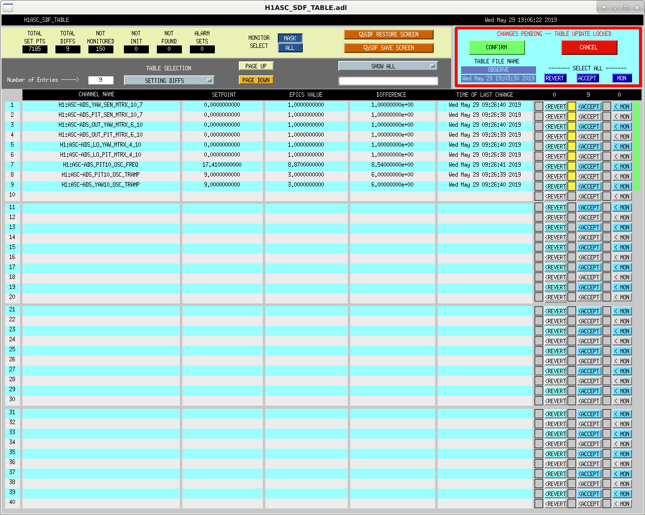
Screenshotting some SDF diffs associated with the ASC ADS. These were caused by the MICH_BRIGHT_ALIGN part of TJ's fast initial alignment, and I think they won't be touched by anything else.
Jenne, Sheila, Georgia, Patrick
We found a couple of problems with the way the DRMI guardian graph was.
Several years ago we created a branch in the DRMI guardian that would allow the DRMI ASC to be offloaded when loccked on 1F, this was to make things easier at a time when 3F locking wasn't working. This wasn't part of the usual procedure, but just an optional branch path in the guardian. At some point the graph for this guardian was changed so that we were offloading the ASC before transitioning to 3F every single lock, which does sometimes cause locklosses.
Additionally, earlier today Jenne found that there was a counter error in the ISC_LOCK OFFLOAD_DRMI_ASC state that meant that we weren't actually offloading the DRMI ASC there, where we intended to be. This is why Georgia's change to the graph last night caused problems.
Now we have edited the guardian so that the things that we need to do after running initial alignment are done in the prep state (not down, so there shouldn't be a need to rerun down), so that the DRMI ASC is only offloaded after we have transitioned to 3F.
In the last lock, while the calibration measurements were happening and while the IFO was thermalizing before the calibration measurements, we took the squeezer offline to check some things that would ideally be checked after the laser current is changed.
The SHG temperature didn't need to be changed, but its conversion efficiency has dropped, so I reset the minimum conversion efficency threshold.
I adjusted the half wave plate to bring the green power into the fiber closer to 20mW, according to the launch diode. I would like to double check the calibration of the two SHG power monitor diodes. I added a parameter file for the squeezer guardians, so hat we would not have the TEC temperature hard coded in multiple places and can update it more easily. (I also changed the temperature to 33.32 degrees).
I then tried to measure the nonlinear gain at a couple of different green powers, to make this easier I also added parameters that would change with green power to the parameter file. I will plot and post the data soon.
We still need to double check the squeezing angle next time we are locked.
The message of these non linear gain checks is that we get consistent enough results for different green powers and different methods of measuring the nonlinear gain.
Looking at the SHG power launch diode and the OPO reflected diode at a time when the OPO was unlocked earlier today, the transmission from the launched green power to incident power on the OPO is 15.8%. I measured the powers using the launch diode for these measurements, but have multiplied everything by 15.8% to make the plots in terms of green power incident on the OPO.
We have wondered if there is something wrong with our estimation of the nonlinear gains, in part because our estimates of losses and phase noise depend on them, and in part because we have had discrepancies when using different methods to measure the nonlinear gain. We measure the nonlinear gain by locking the OPO with green light, and injecting a low power IR seed beam through the path used for the CLF. We measure the IR power on a diode in the homodyne path, while using a PZT to modulate the phase of the seed between amplification and deamplification. One method for estimating the nonlinear gain is to measure the maximum and minimum of the transmitted IR, and use these to derive the nonlinear gain. Another method is to first measure the unamplified seed by slowly scanning the OPO with no green power.
Here the normalized non linear interaction strength is x = sqrt(P/P thresh) and the maximum amplification (nonlinear gain) = 1/(1-x)^2 while the minimum from deamplification is 1/(1+x)^2. In order to estimate x from the ratio of the max/min we get x = (sqrt(max/min)-1)/(sqrt(max/min)+1)
The first plot shows the amplification and deamplification measured for different green powers, with the expectation for a threshold of 31mW plotted for reference. This seems fairly consistent with expectations. The second attached plot is intended to help compare the three possible methods of estimating the normalized non-linear interaction strength (or the threshold) from each of these measurements. (Based on the ratio of maximum over minimum, or max/ unamplified or minimum / unamplified) The upper subplot shows x, while the lower plot shows the infered threshold based on each measurement. While there is a systematic error between the different techniques, as is most clear from the threshold power plot, it is not large enough to really have much of an impact on the estimated interaction strength.
Note: I measured the dark offset on the diode used to measure the amplified seed while the OPO was scanning, and treated this as a dark offset which is subtracted from all measurements. If I ignore this (set it to 0), I do get large discrepancies between these methods.
J. Driggers, J. Kissel
We've gathered some new data on the DARM loop both in support of regular check-ins on the calibration as well as in prep for a potential increase in IFO power tomorrow, and further investigations in to "L to A to L" coupling in the ISC control scheme:

Standard sensing function suite:
/ligo/svncommon/CalSVN/aligocalibration/trunk/Runs/O3/H1/Measurements/FullIFOSensingTFs/
2019-05-29_H1_DARM_OLGTF_LF_SS_5to1100Hz_15min.xml
2019-05-29_H1_OMCDCPDSUM_to_DARMIN1.xml
2019-05-29_H1_PCAL2DARMTF_BB.xml
2019-05-29_H1_PCAL2DARMTF_LF_SS_5t1100Hz_10min.xml
Some incomplete data during the spot position move:
/ligo/svncommon/CalSVN/aligocalibration/trunk/Runs/O3/H1/Measurements/FullIFOSensingTFs/
2019-05-29_H1_PCAL2DARMTF_BB_postspotmove.xml
2019-05-29_H1_DARM_OLGTF_LF_SS_5to1100Hz_15min_postspotmove.xml
Data analysis and results to come later.
For this spot position move to investigate the L-to-ASC-to_L path, I moved the ETMX spot in pitch only, from -18.2mm (P2L gain of 4.85) to about -9.1mm (P2L gain of 2.85). It seems that something in the ASC went unstable and caused the lockloss, although I'm not sure if that's because we were starting the second cal measurement at low frequencies, or if it would have rung up anyway while we sat for a few tens of minutes at this unusual spot position.
Sheila, Georgia, Jenne
Today we took some commissioning time to try to increase the input power. The increase in input power went fairly well, but we had many locklosses due to problems unrelated to power up, more likely related to Tuesday maintence. In total we spent about 3-4 hours today commisioning, although the observatory mode was set to commisioning the entire time.
Increasing power:
Other problems:
most of our locklosses today were unrelated to powering up, we lost lock twice for reasons that were related to our commissioning efforts, the rest of our many locklosses seem to be related to other problems. We have had MC1+3 T2 osem glitches 3 times today, 49257 the first two times caused locklosses, and the third time we were able to stay locked.
We also have had many similar locklosses in the states where we engage ASC and transition to DC readout before powering up. We don't understand this, and the problems seem to have started yesterday.
Here are the locklosses from our attempts to power up to 40W that day:
first attempt: 1241979858 lost lock due to MC1 glitch
2nd: 1241988915
3rd: 1241995833
4th and final: 1242014355