This logpost is a follow up to the executive summary on PR3 OSEM estimator Filter and Blend design [LHO: 86563]
Edgard, Brian, Ivey.
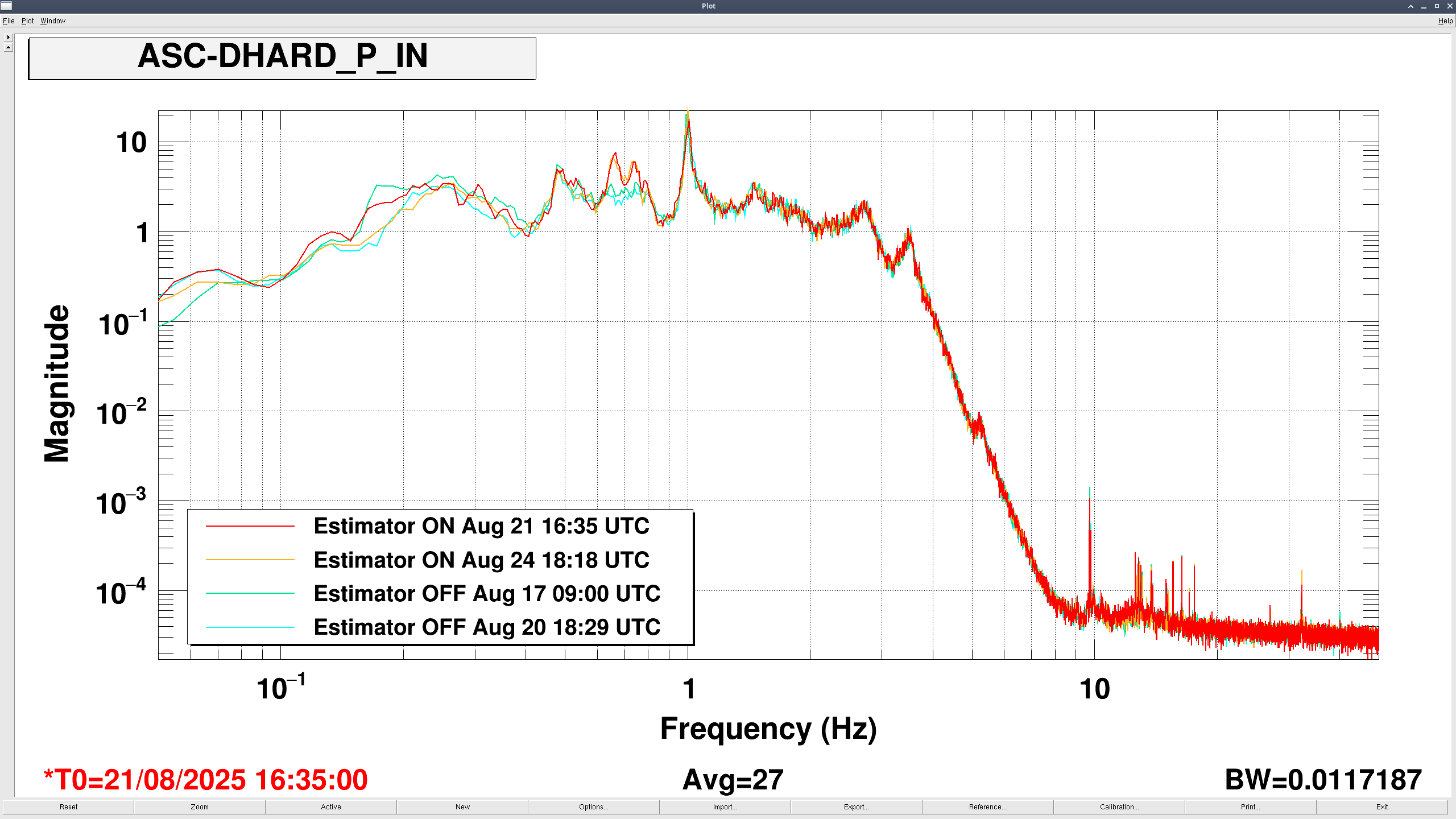
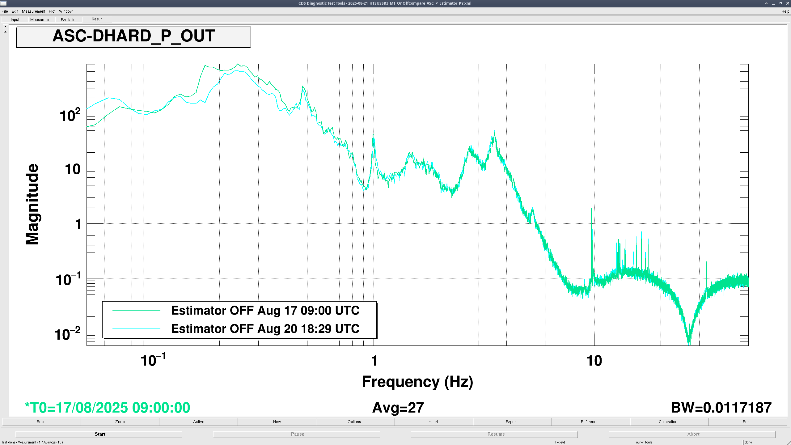
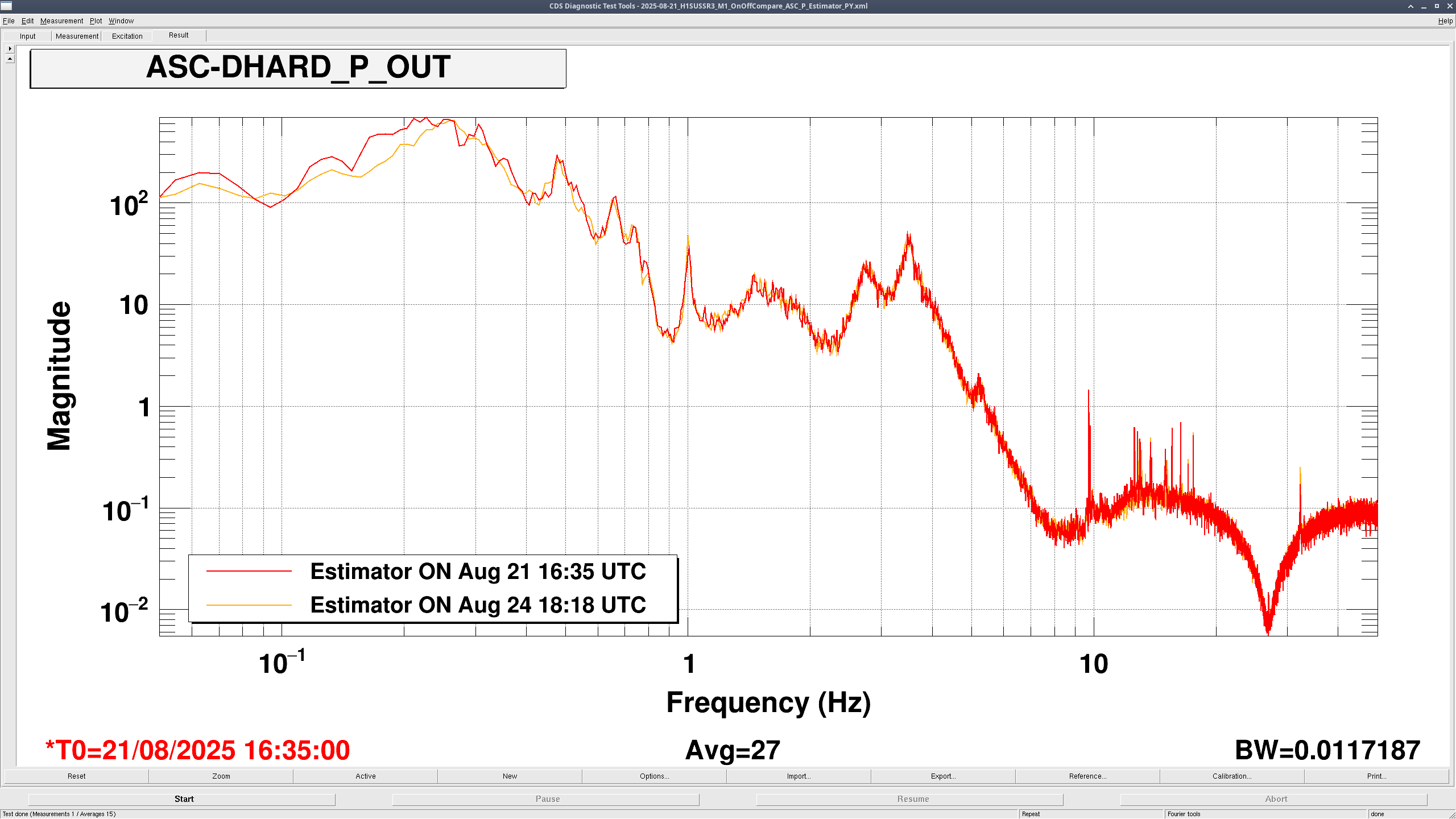
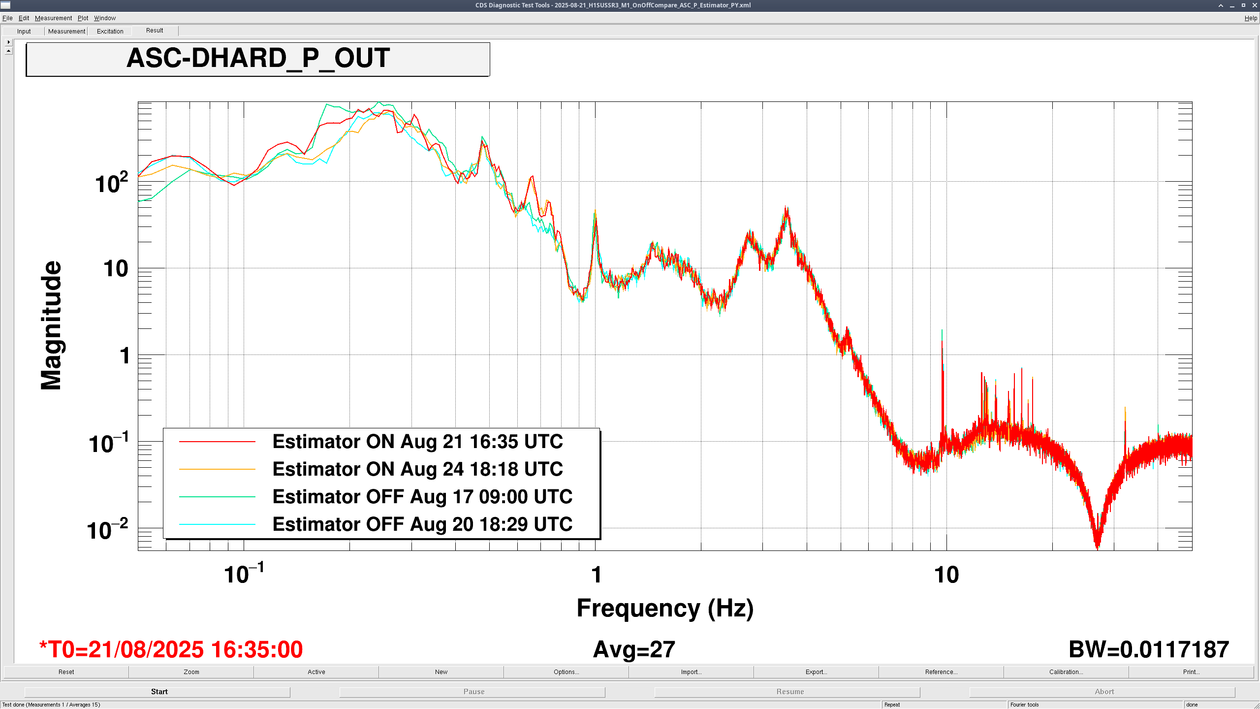
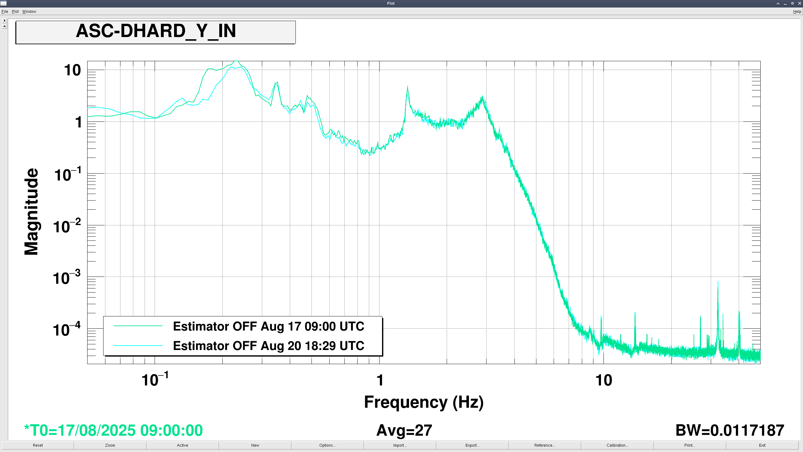
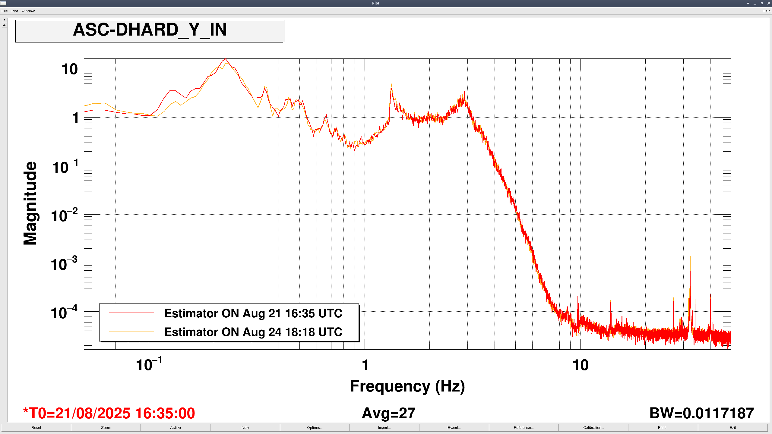
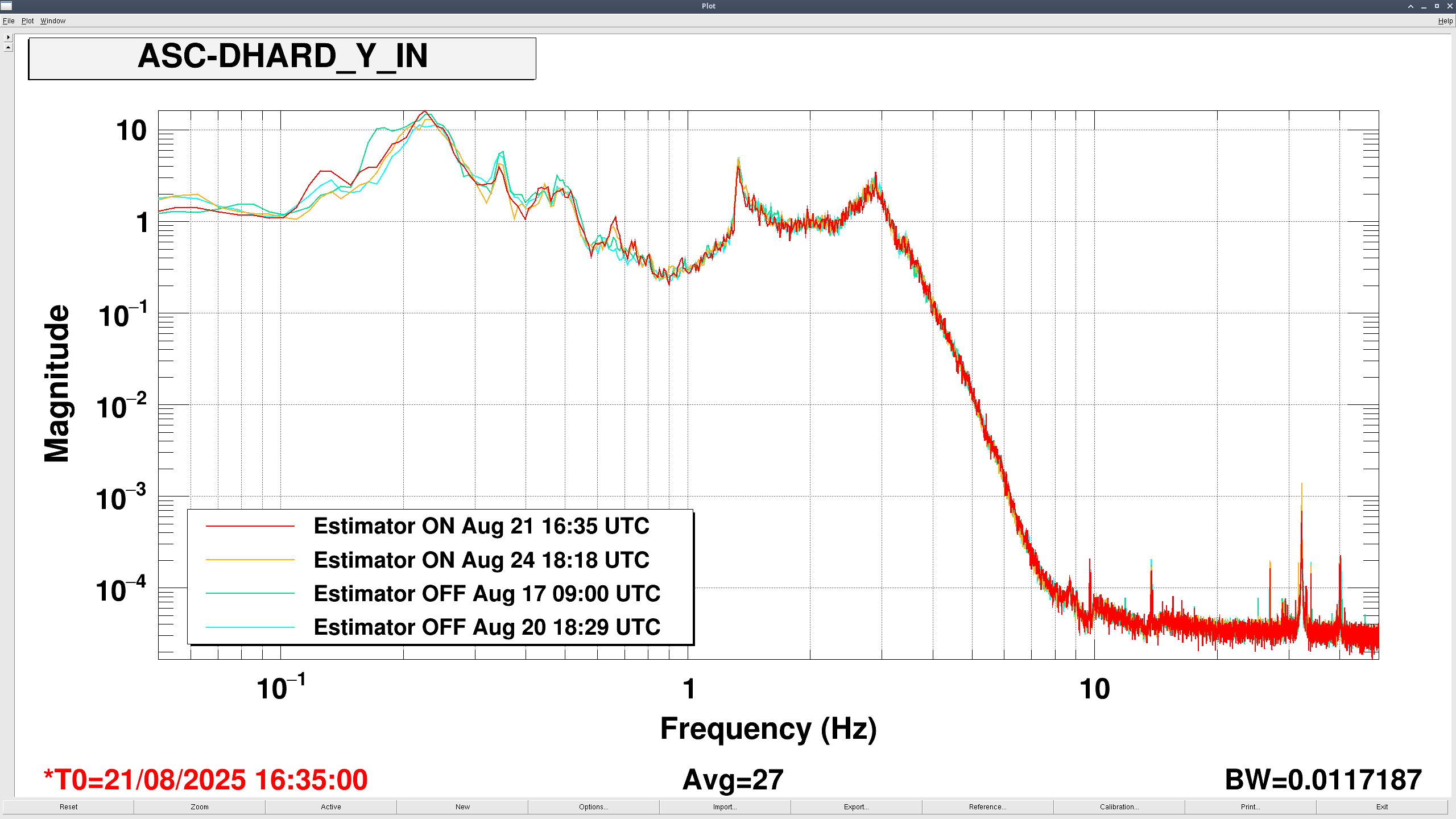
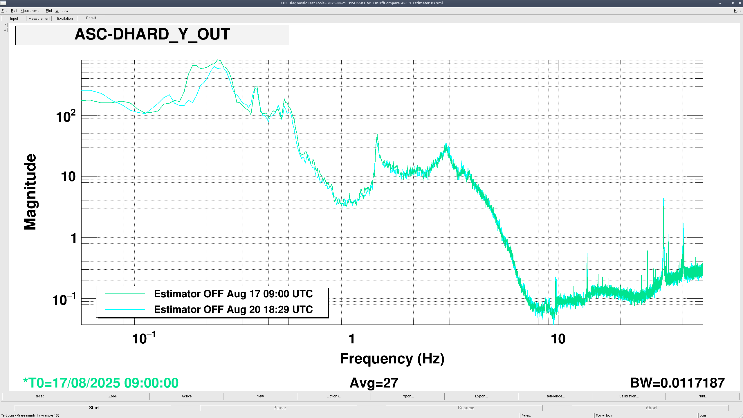
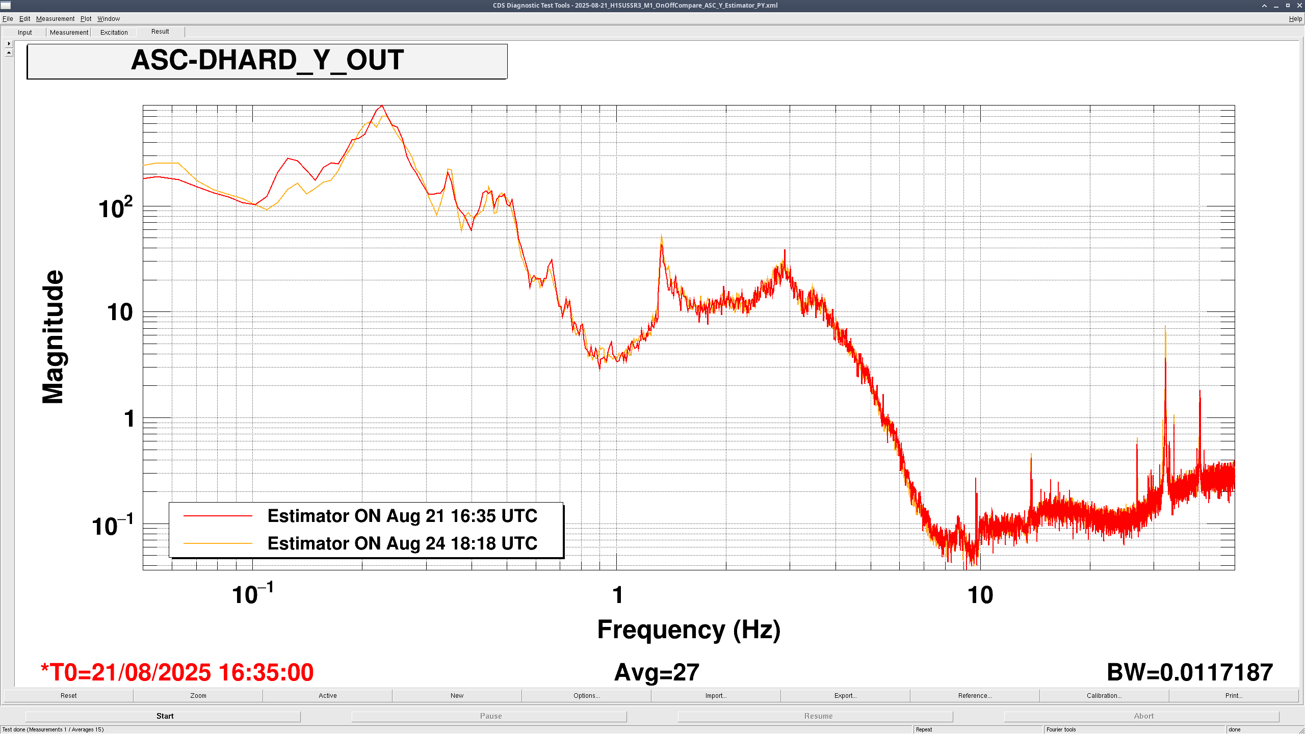
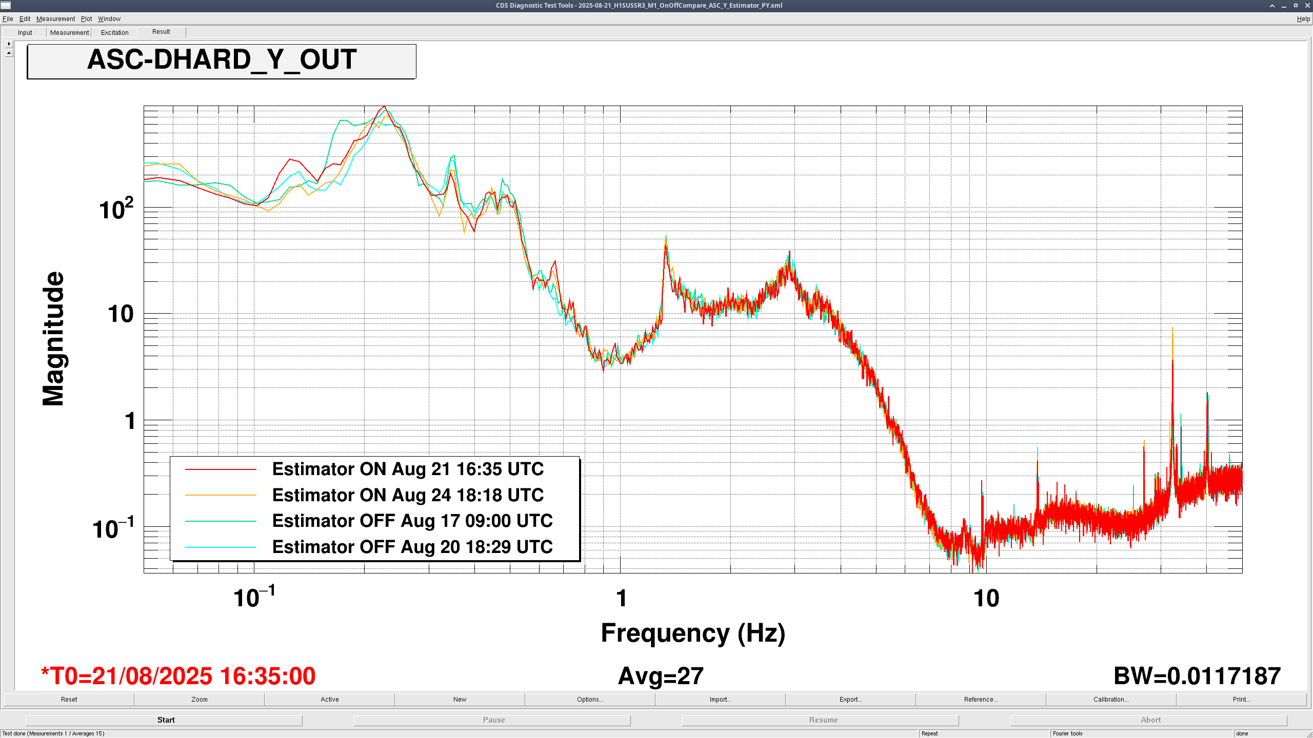
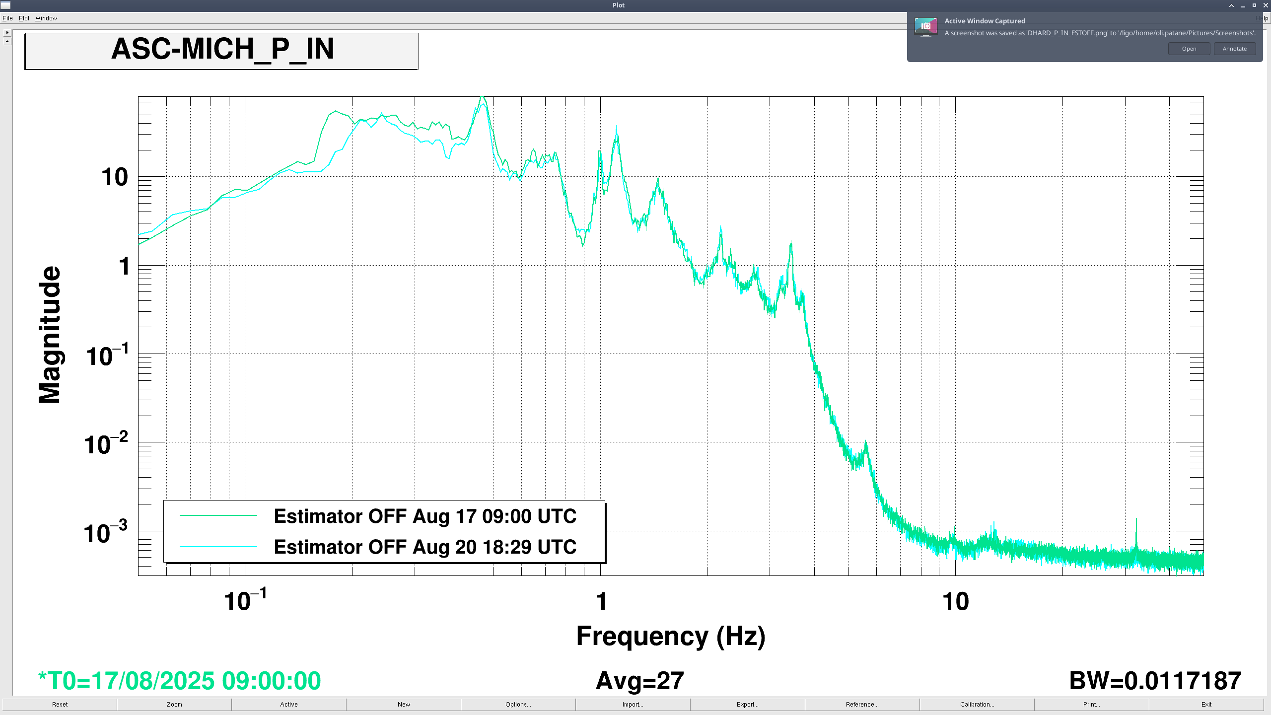
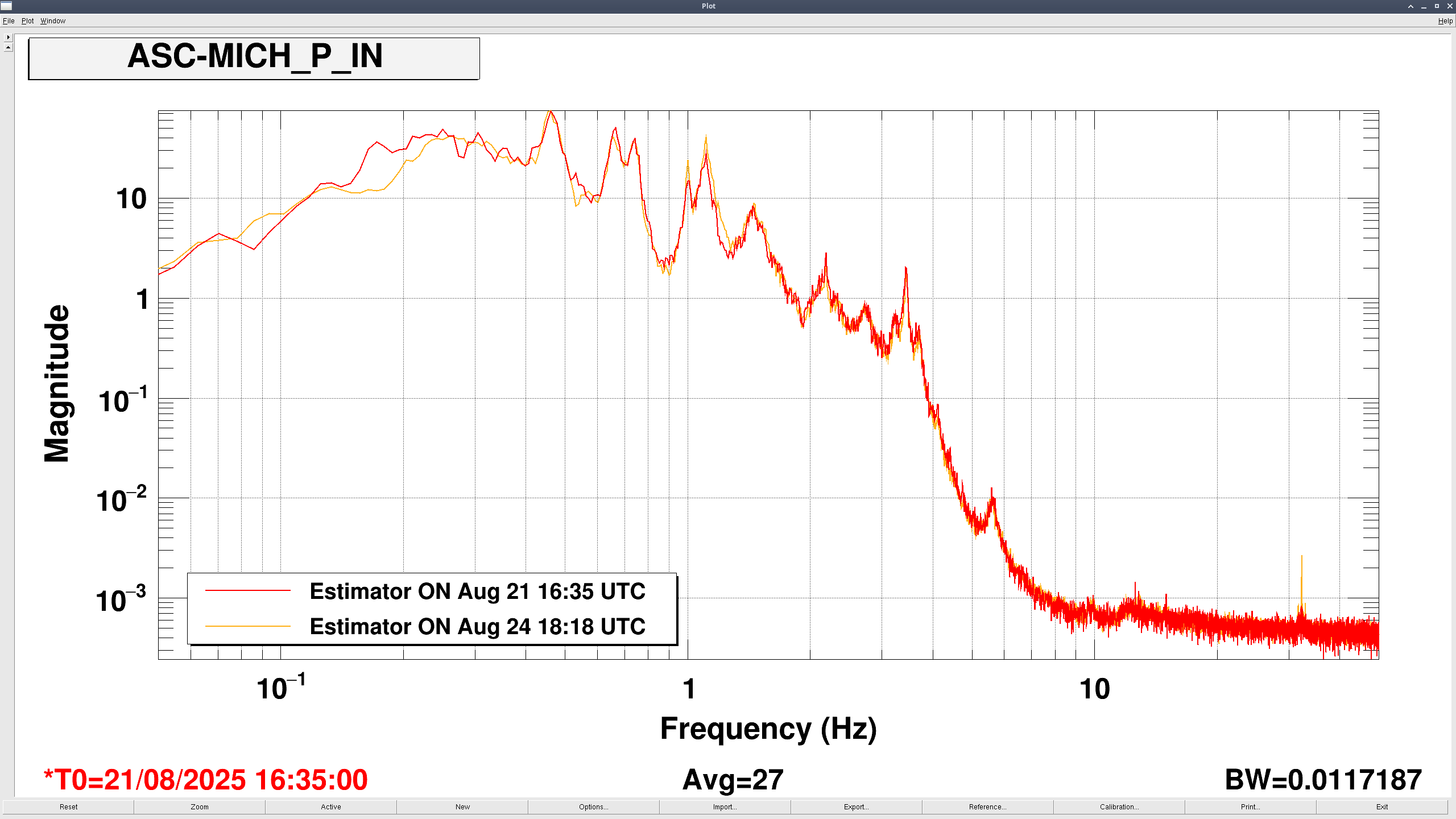
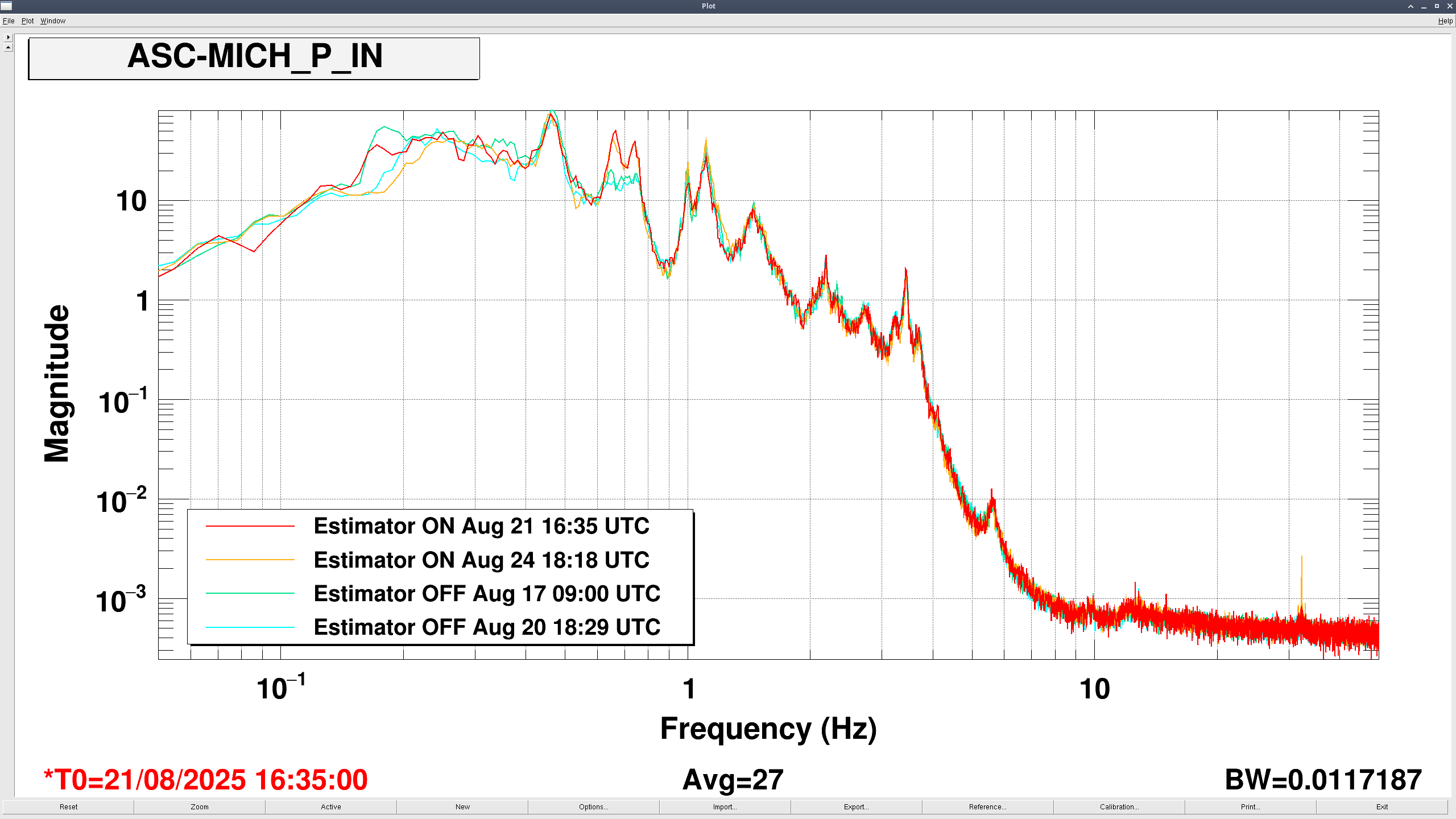
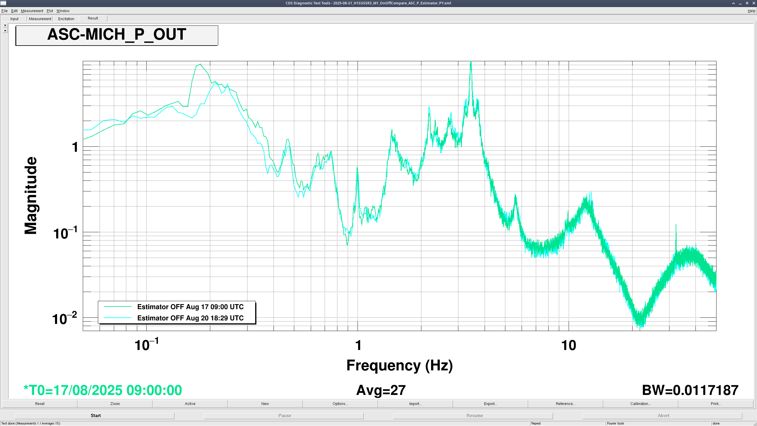
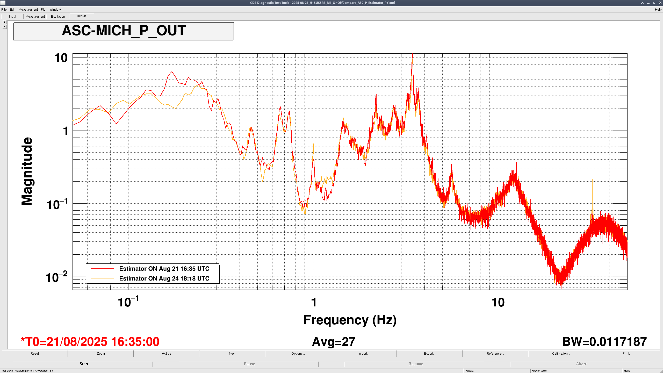
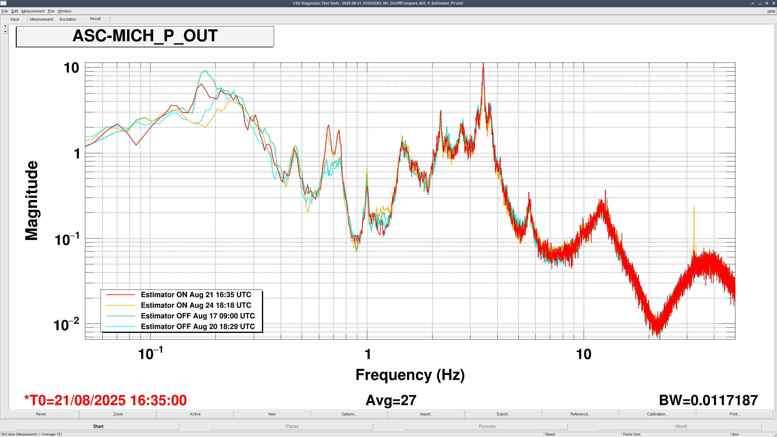
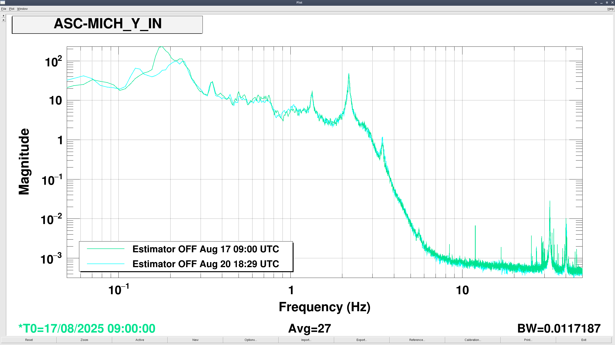
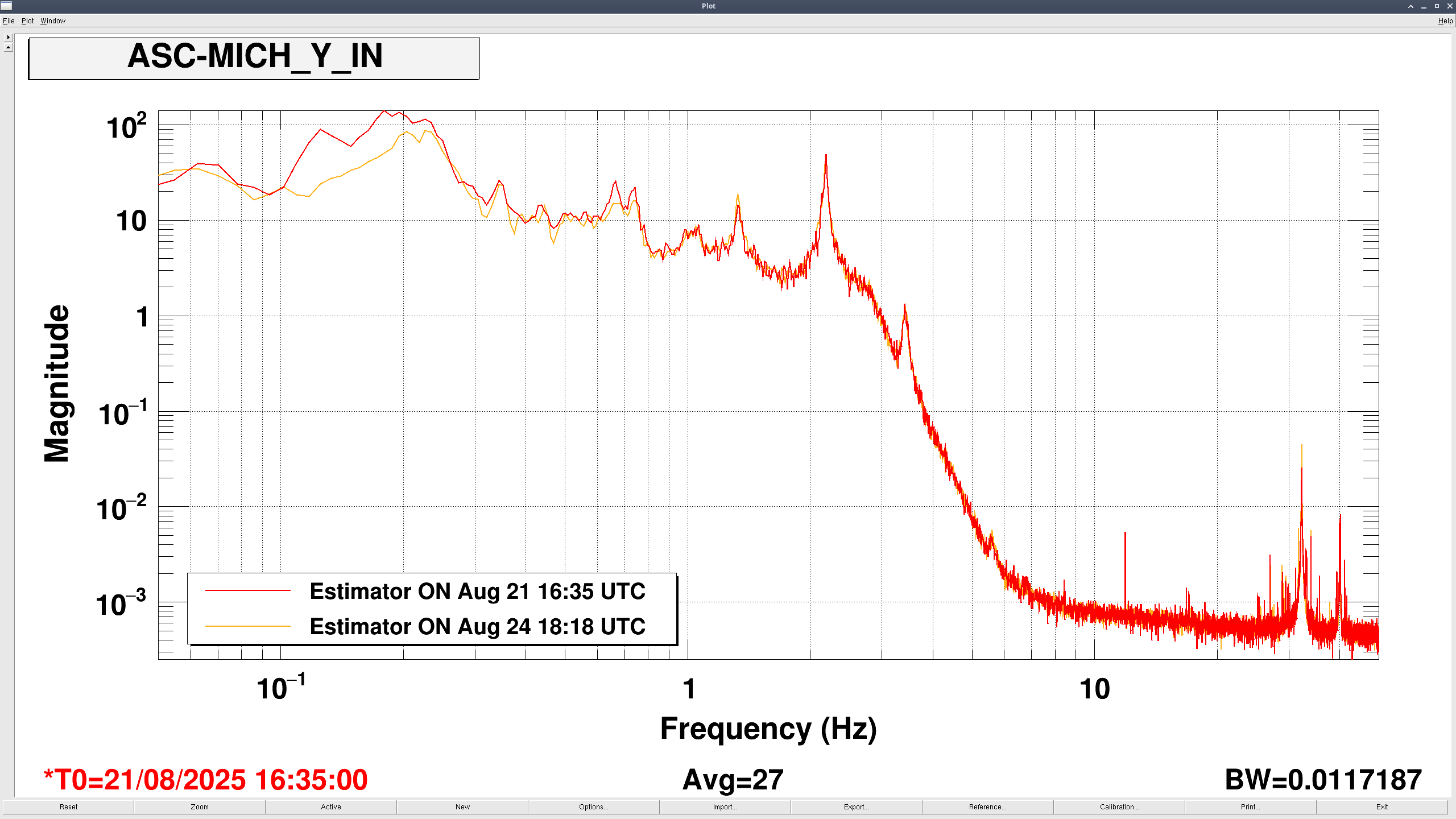
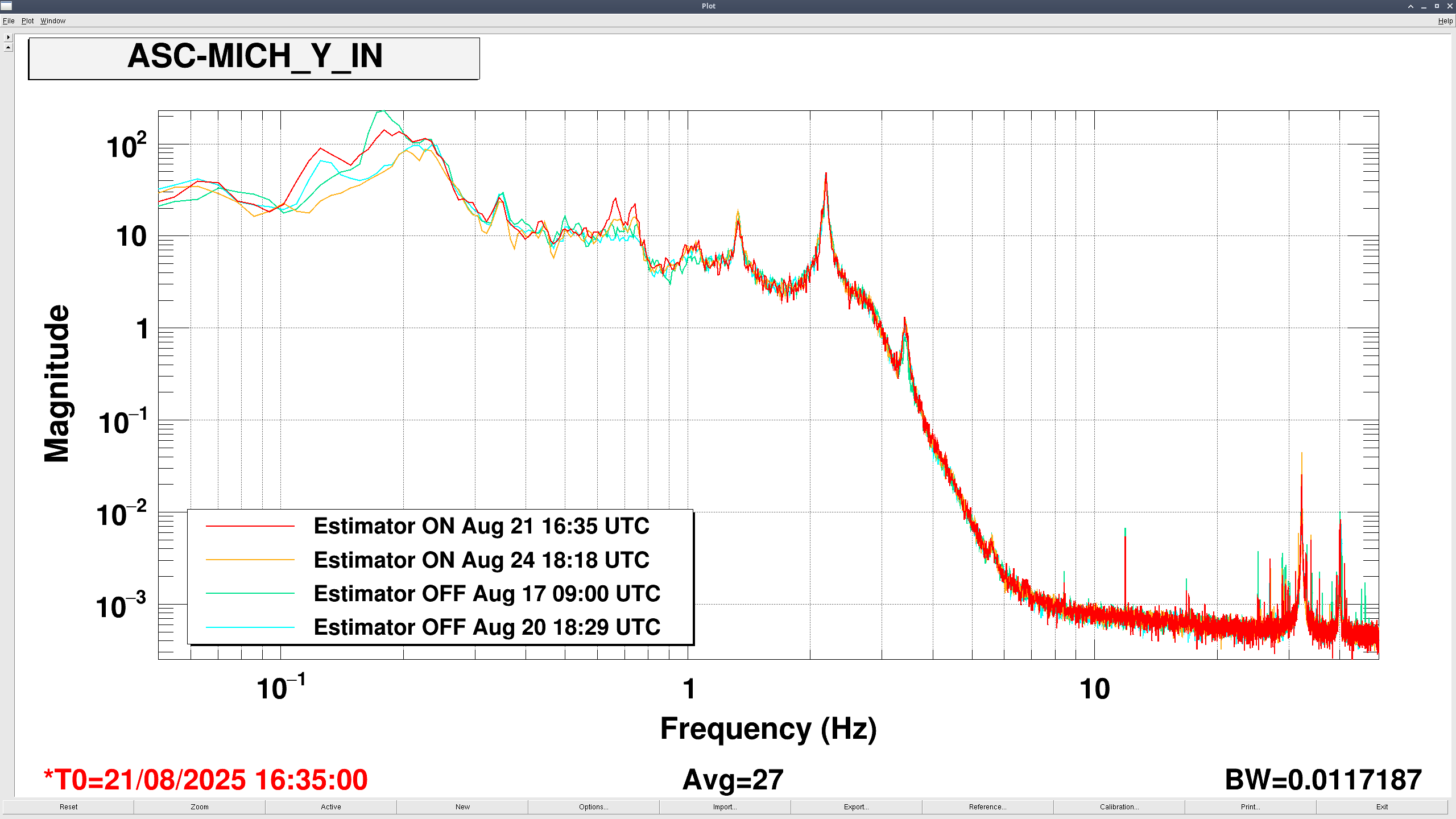
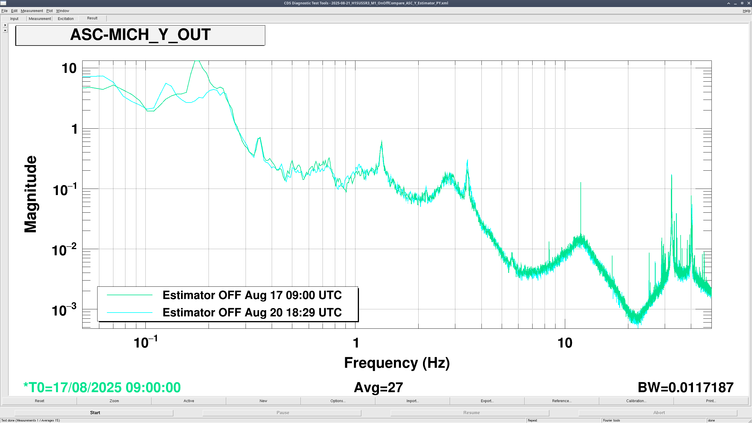
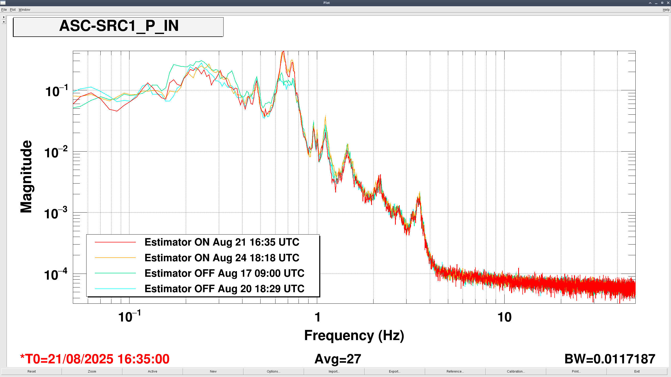
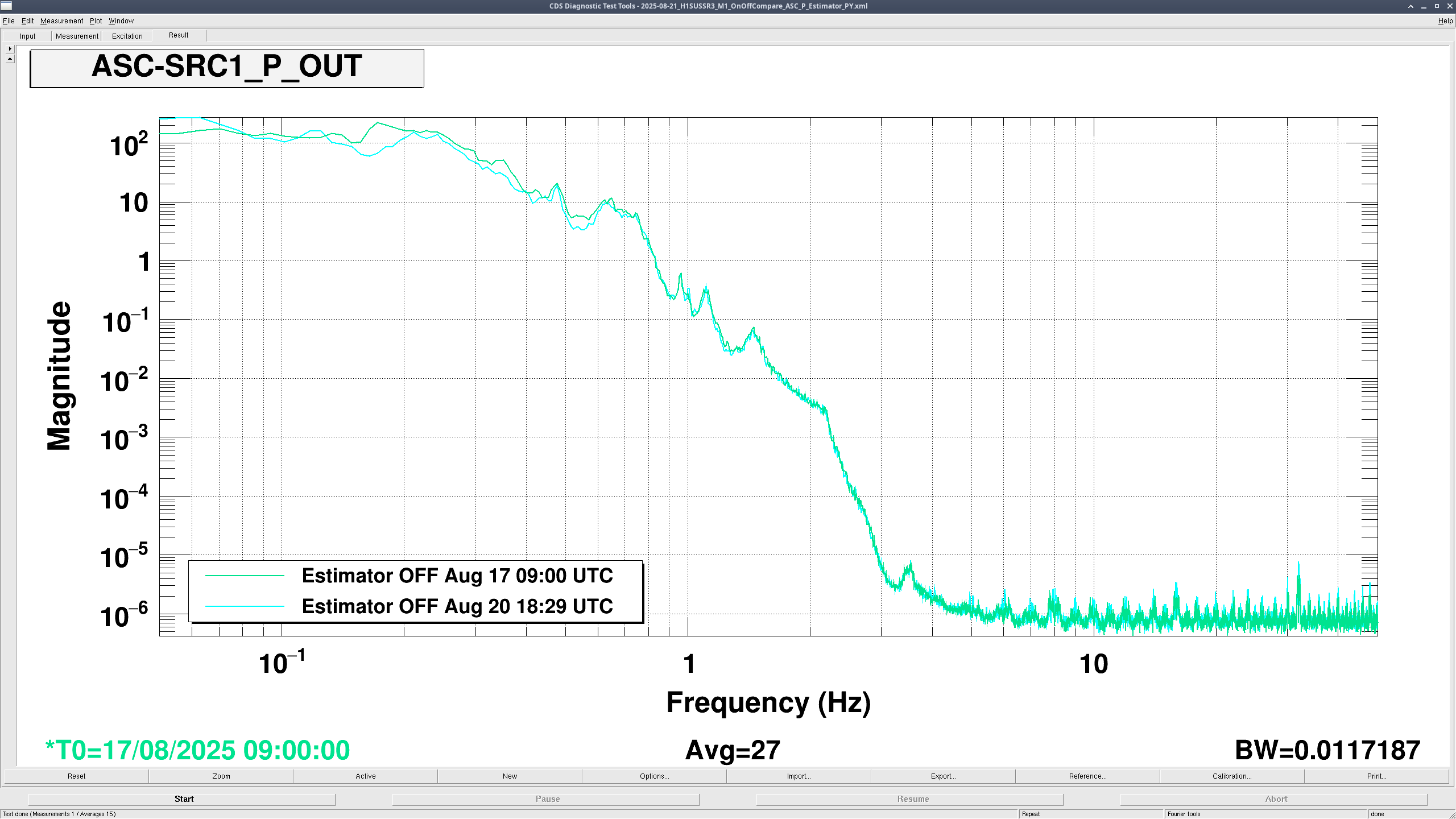
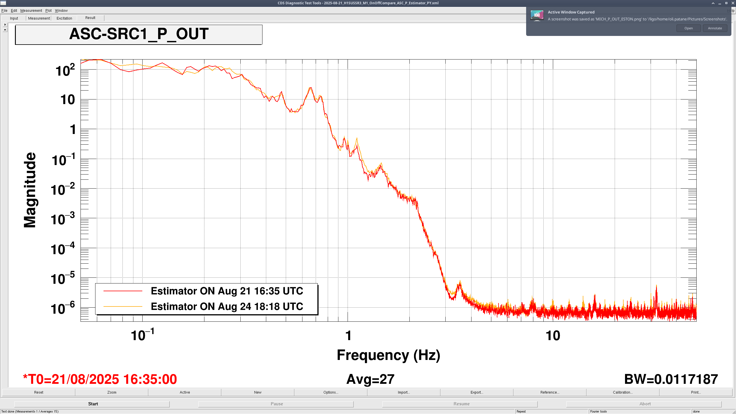
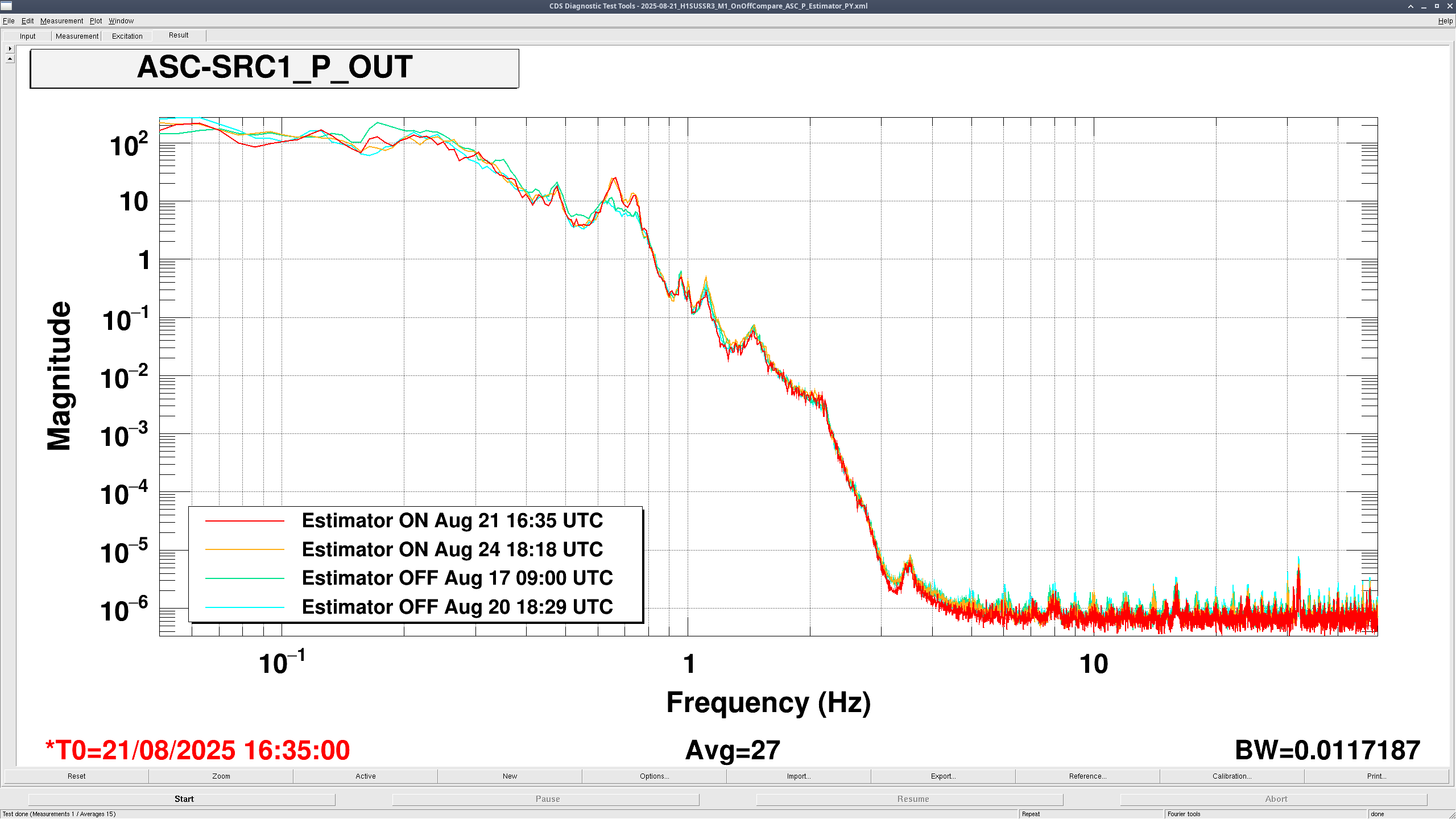
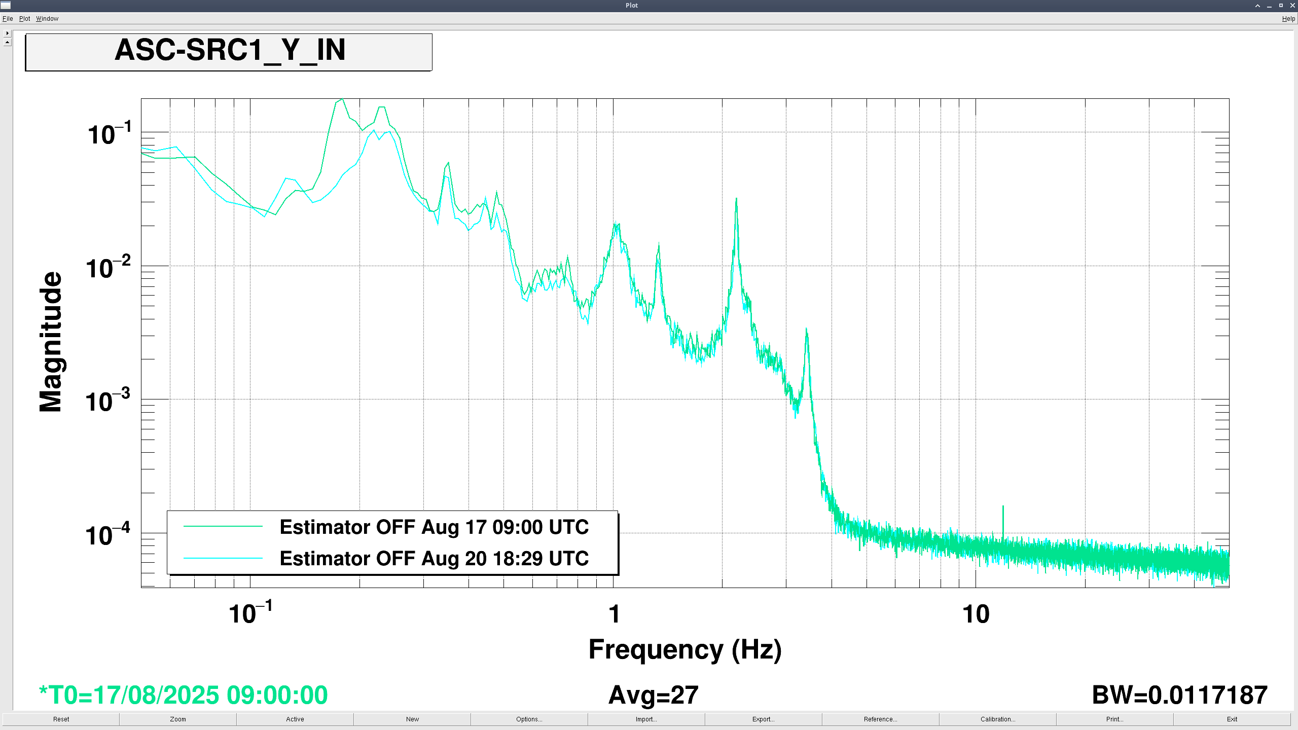
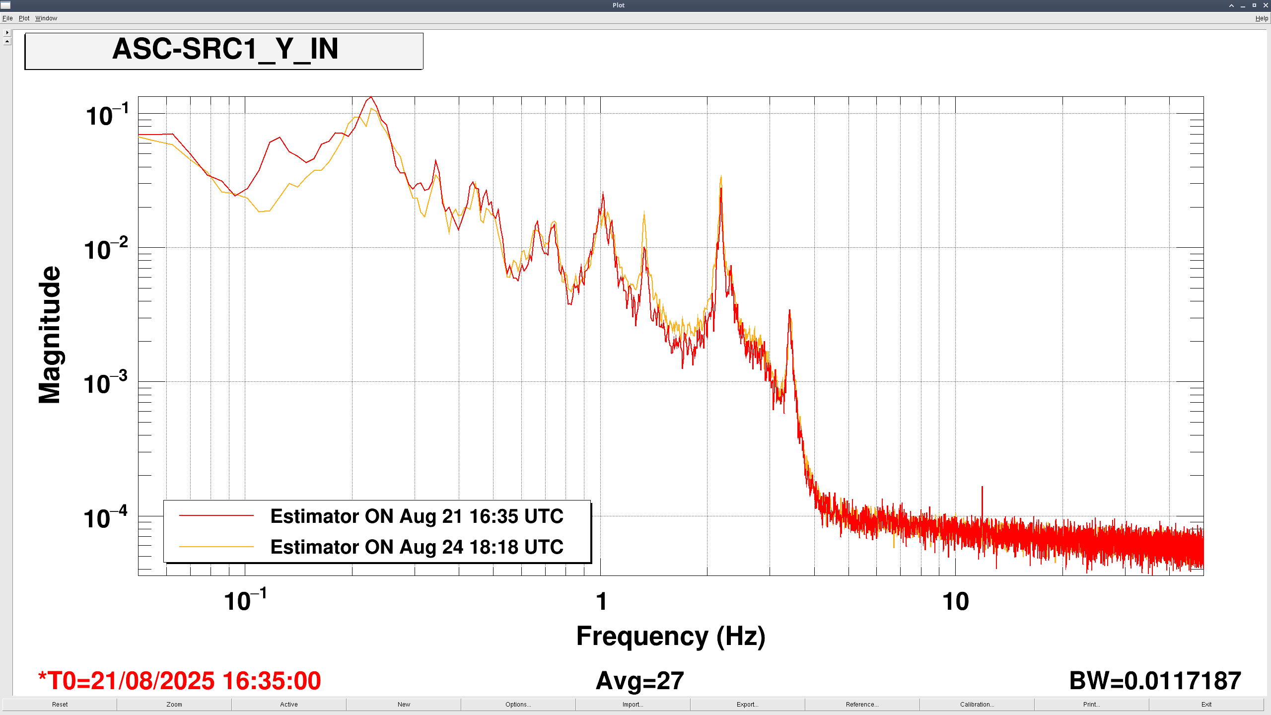
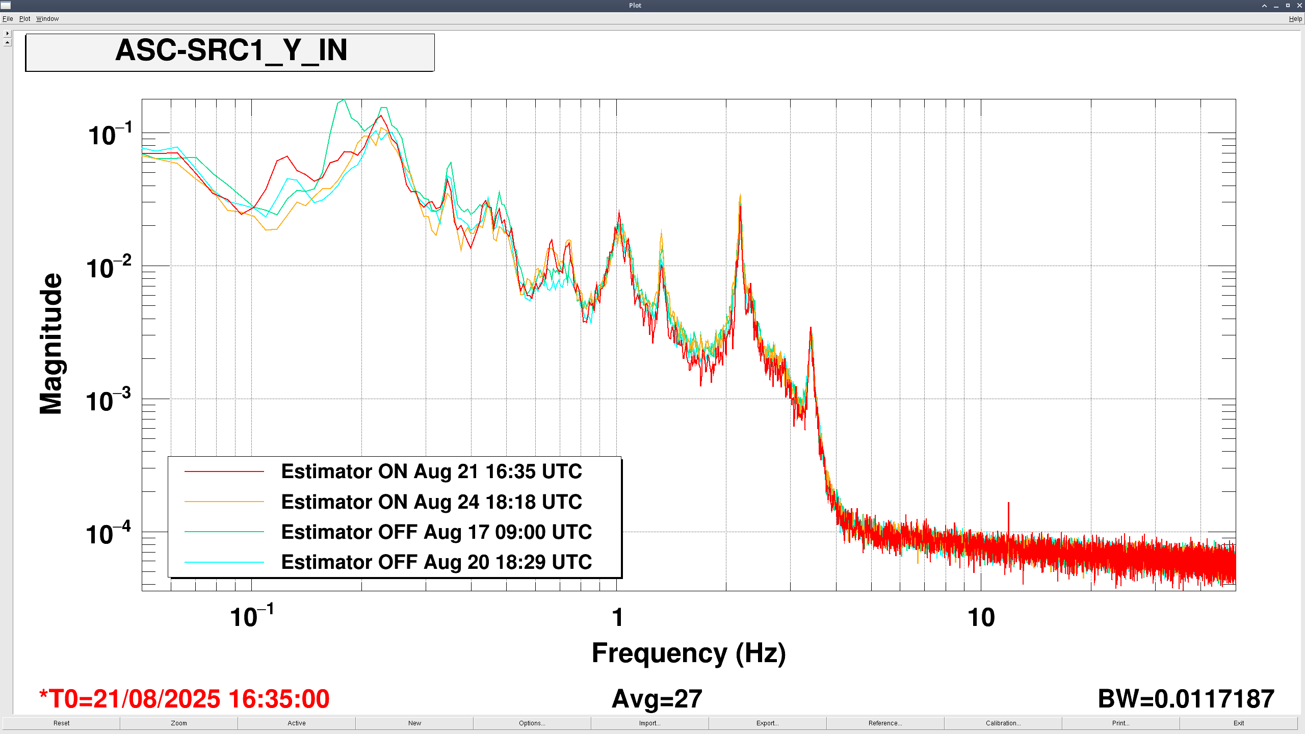
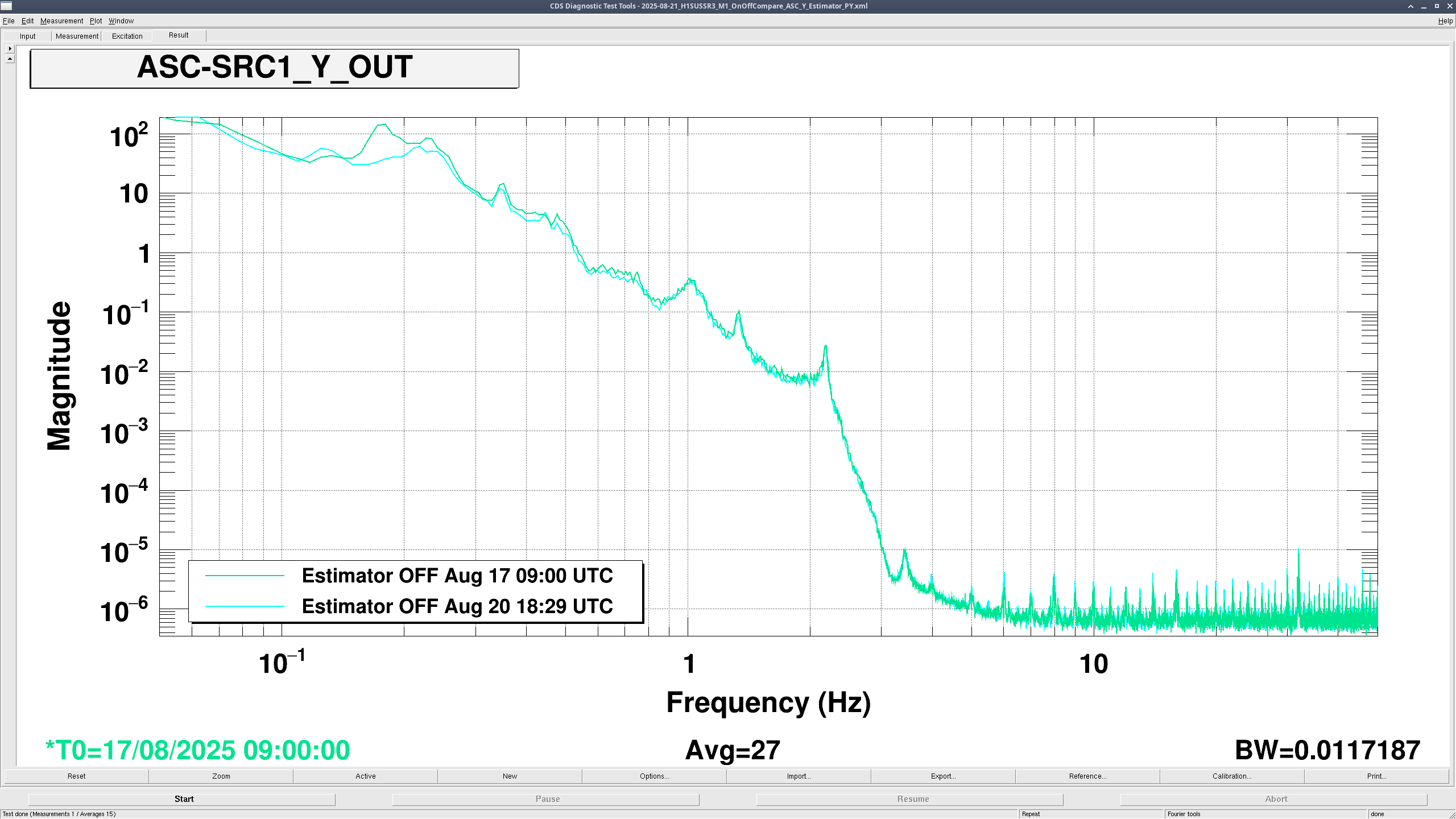
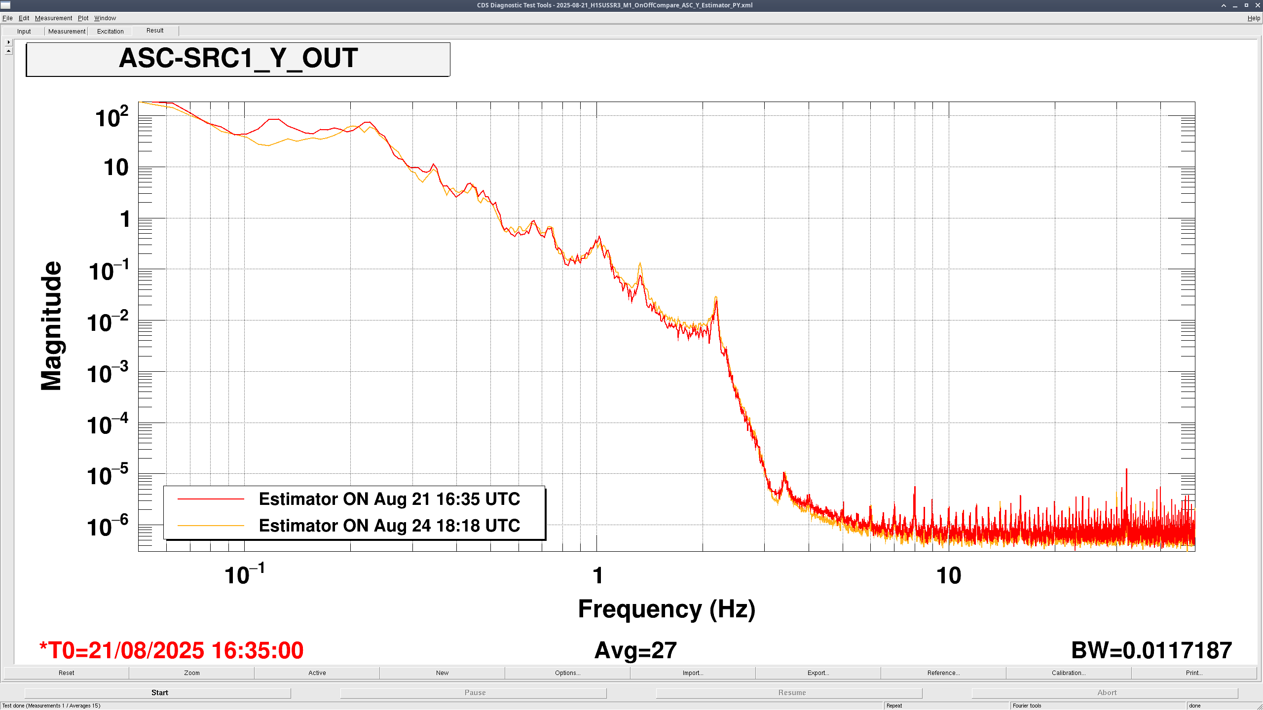
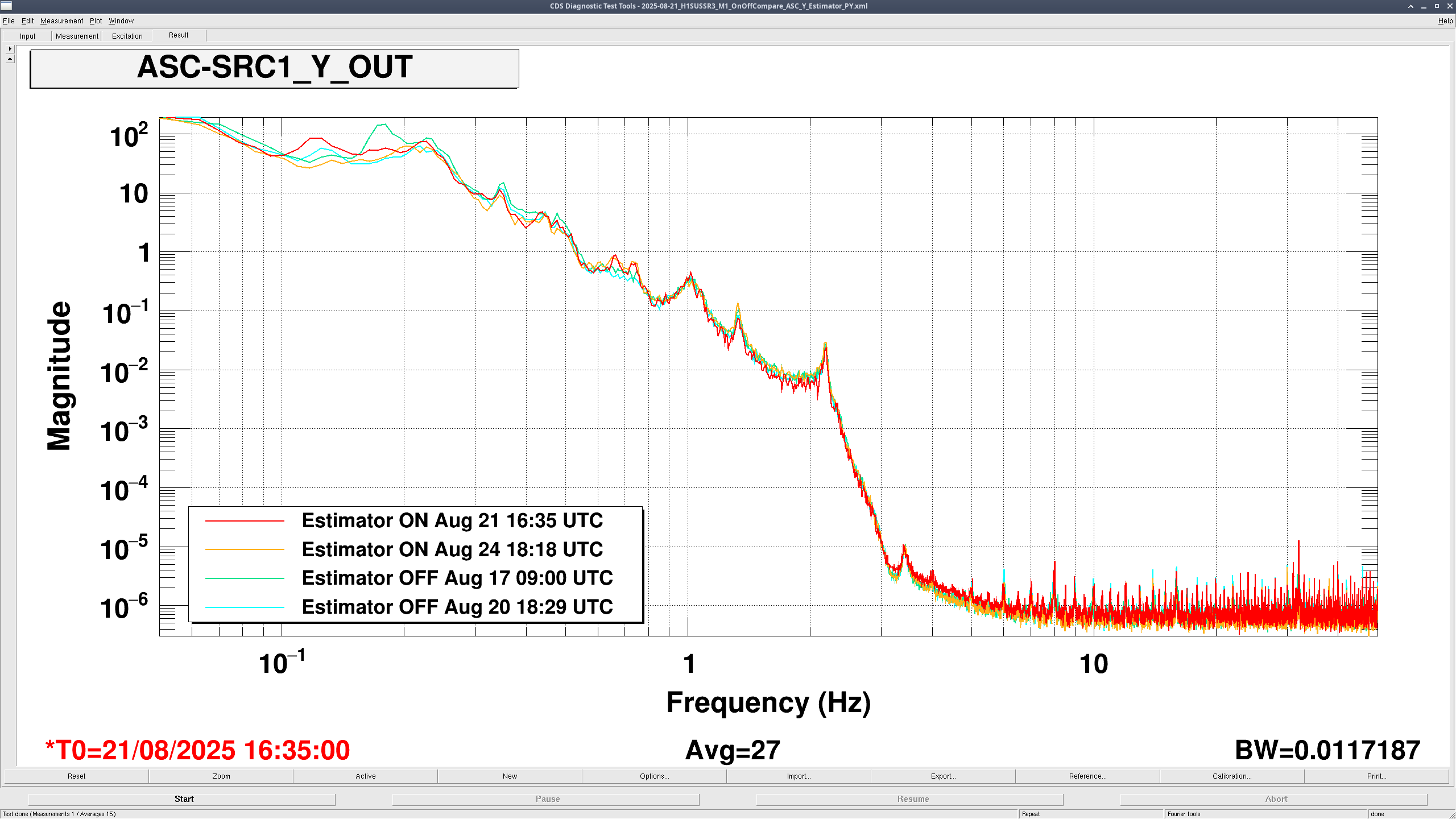
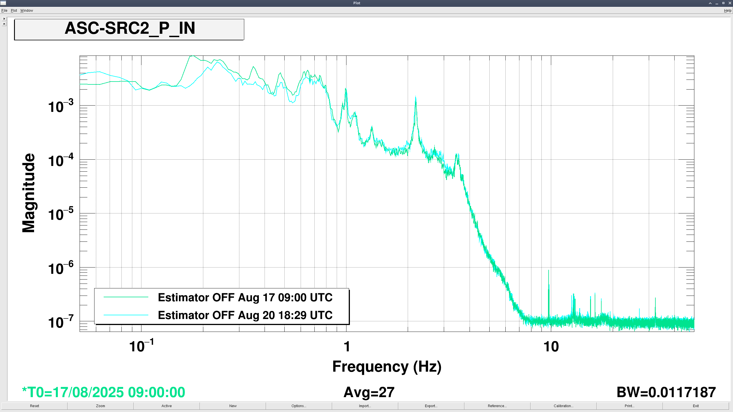
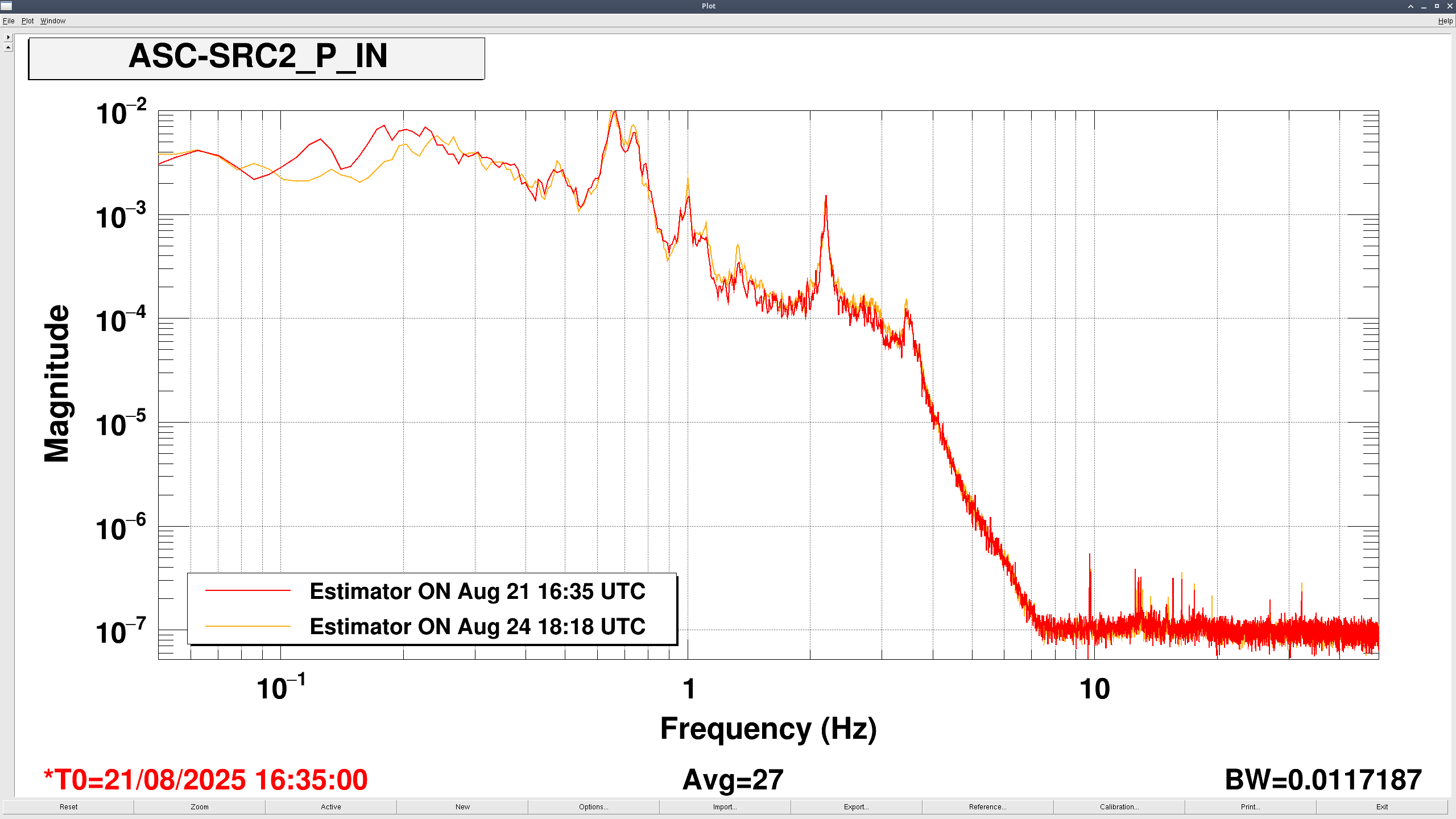
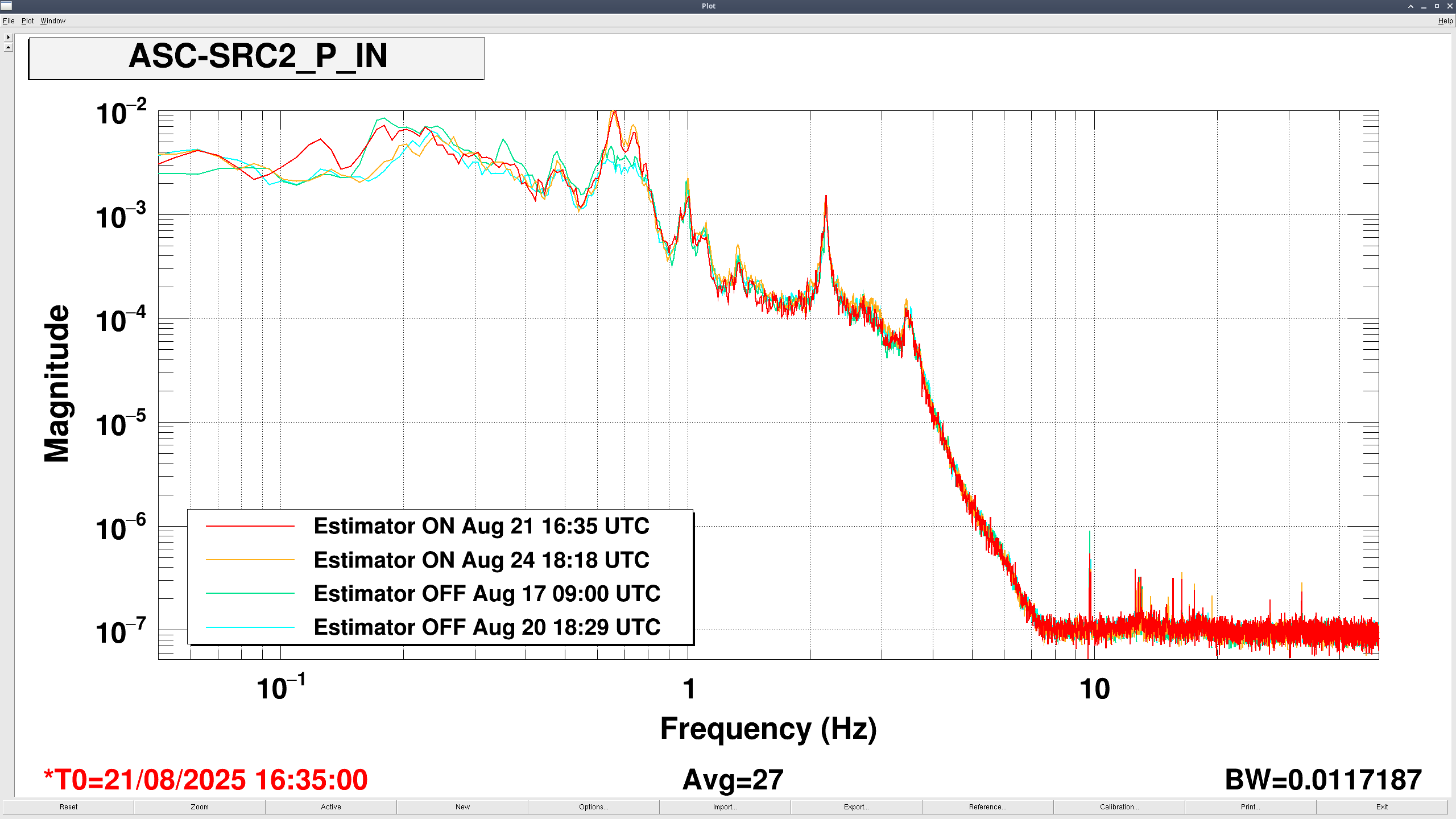
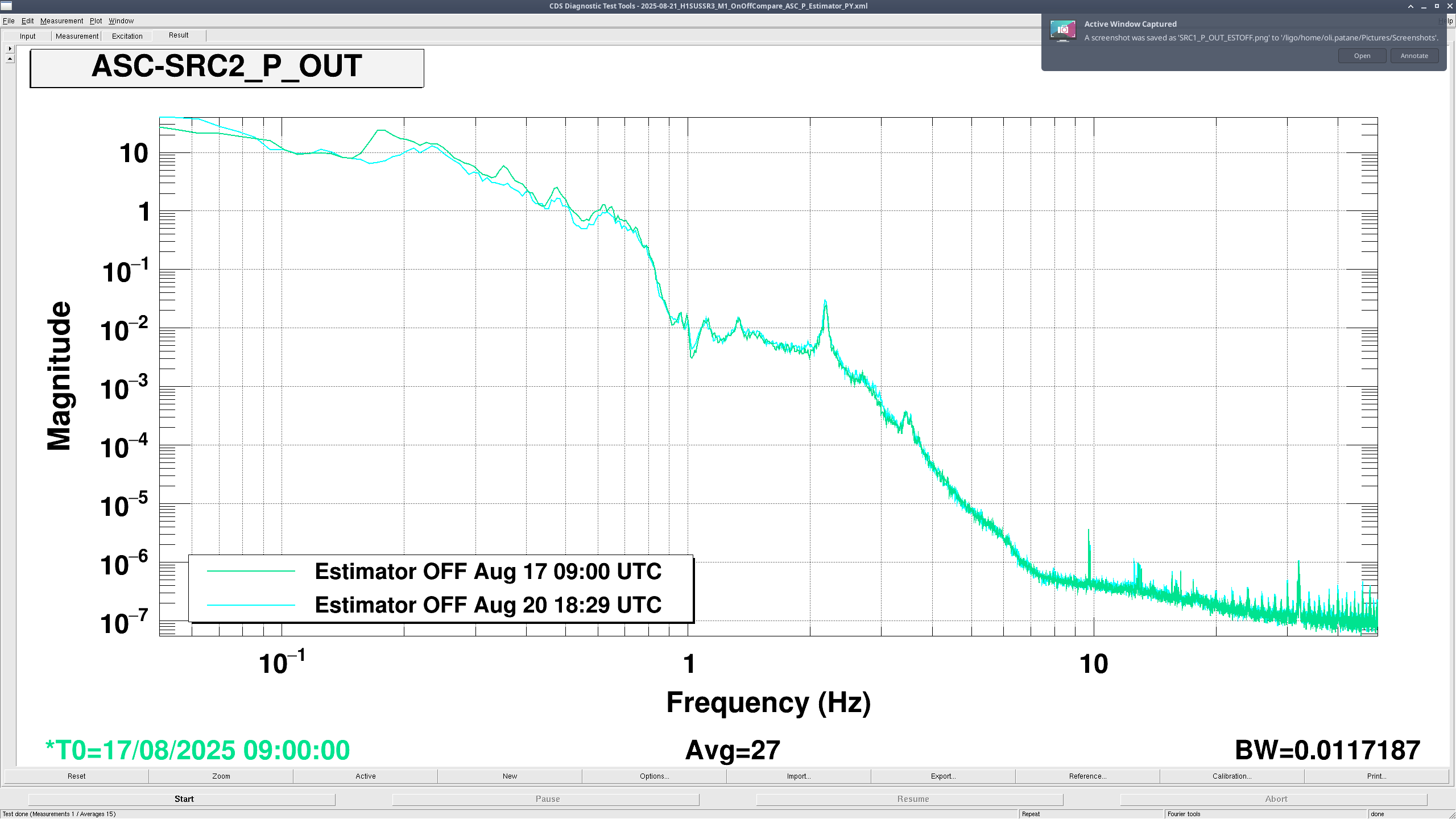
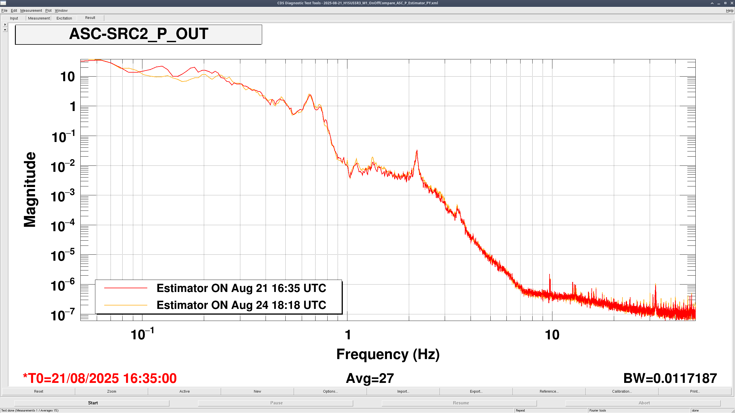
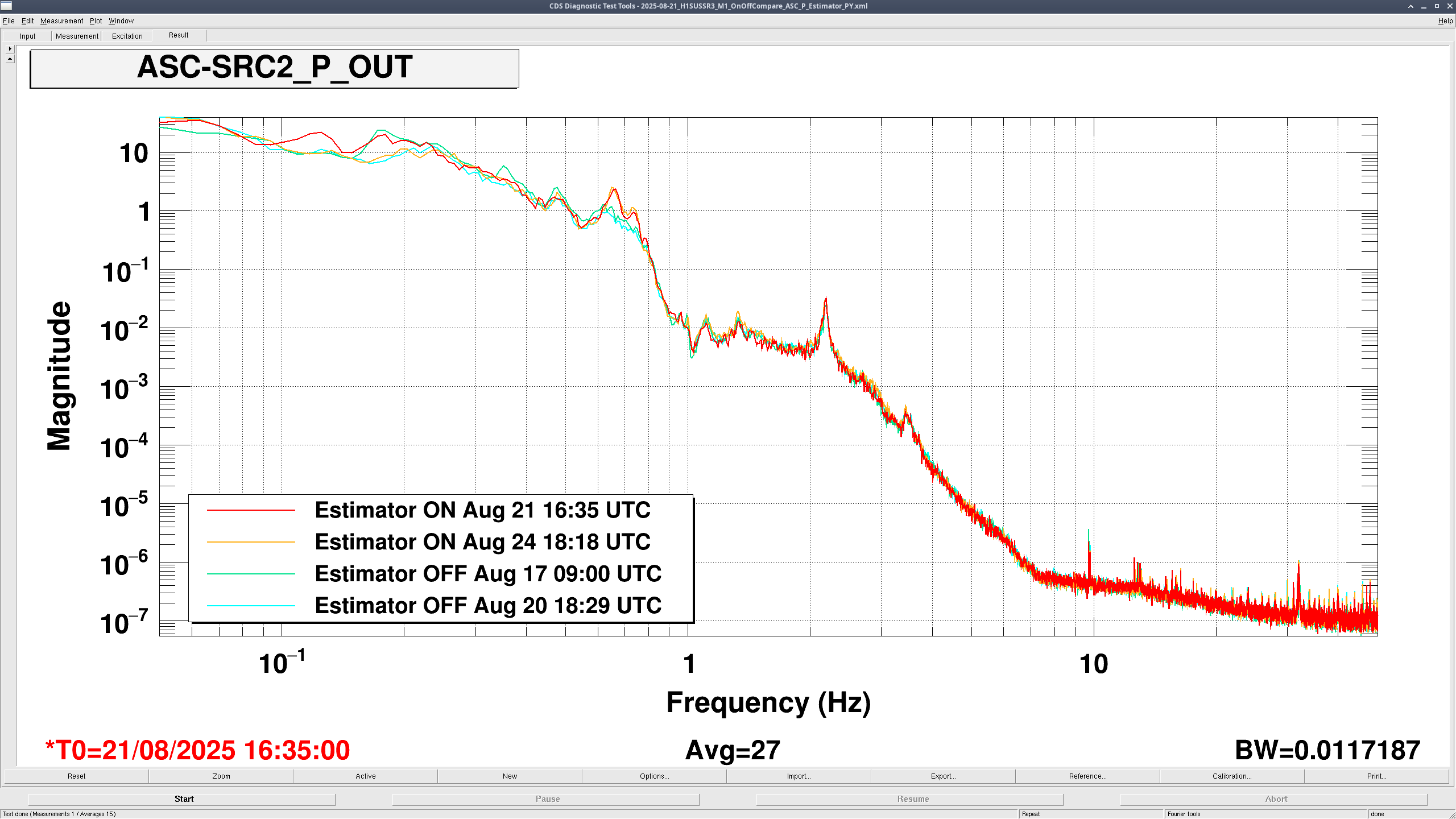
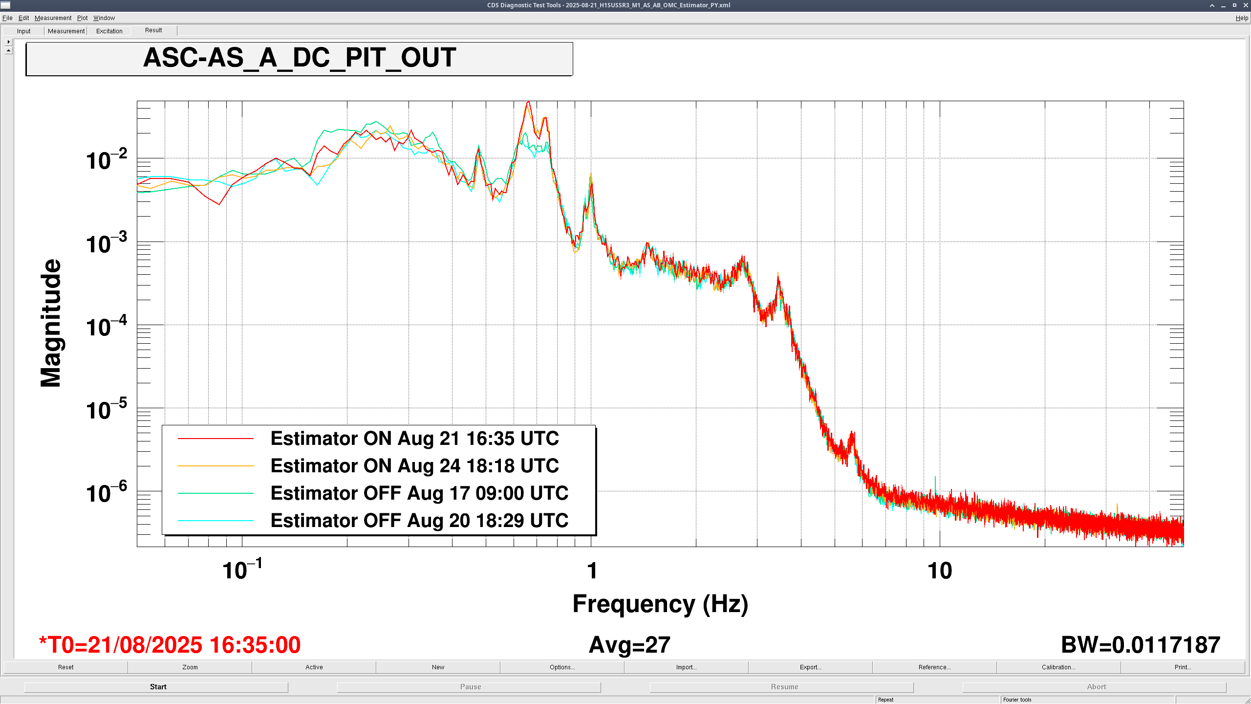
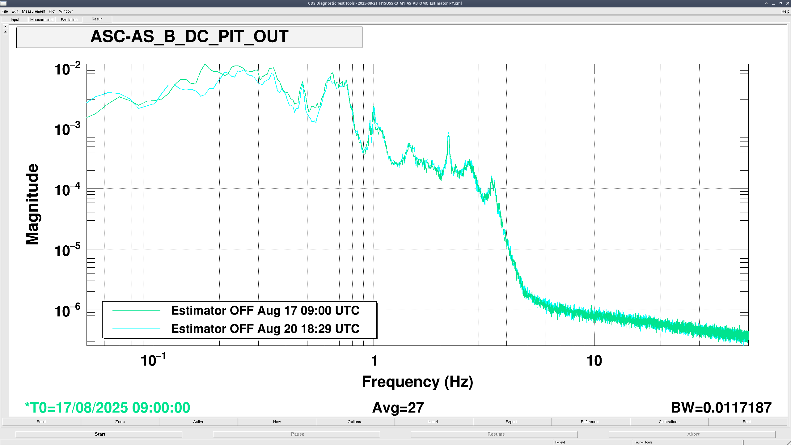
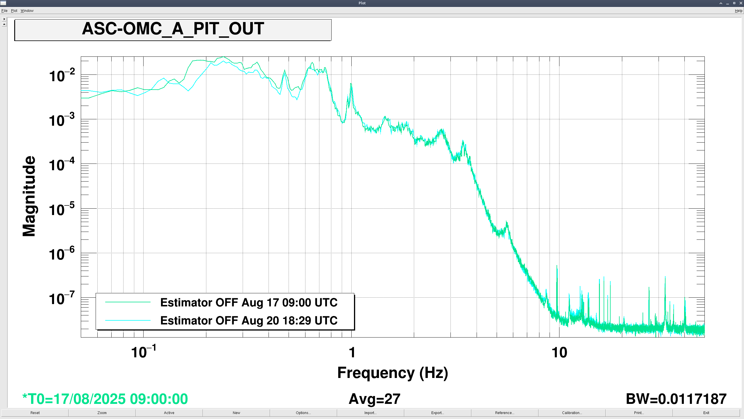
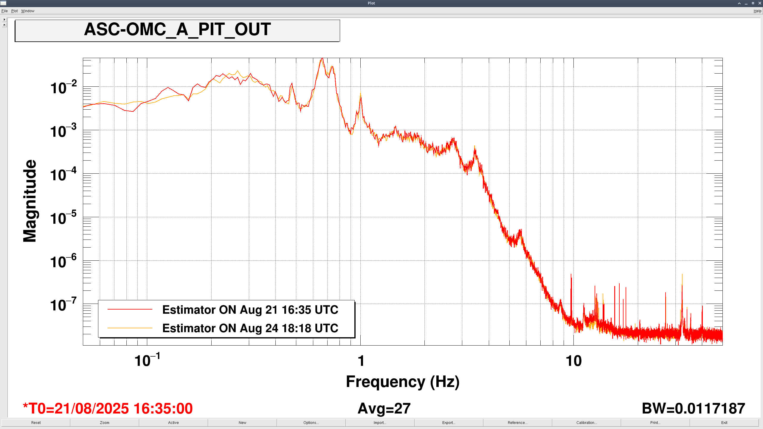
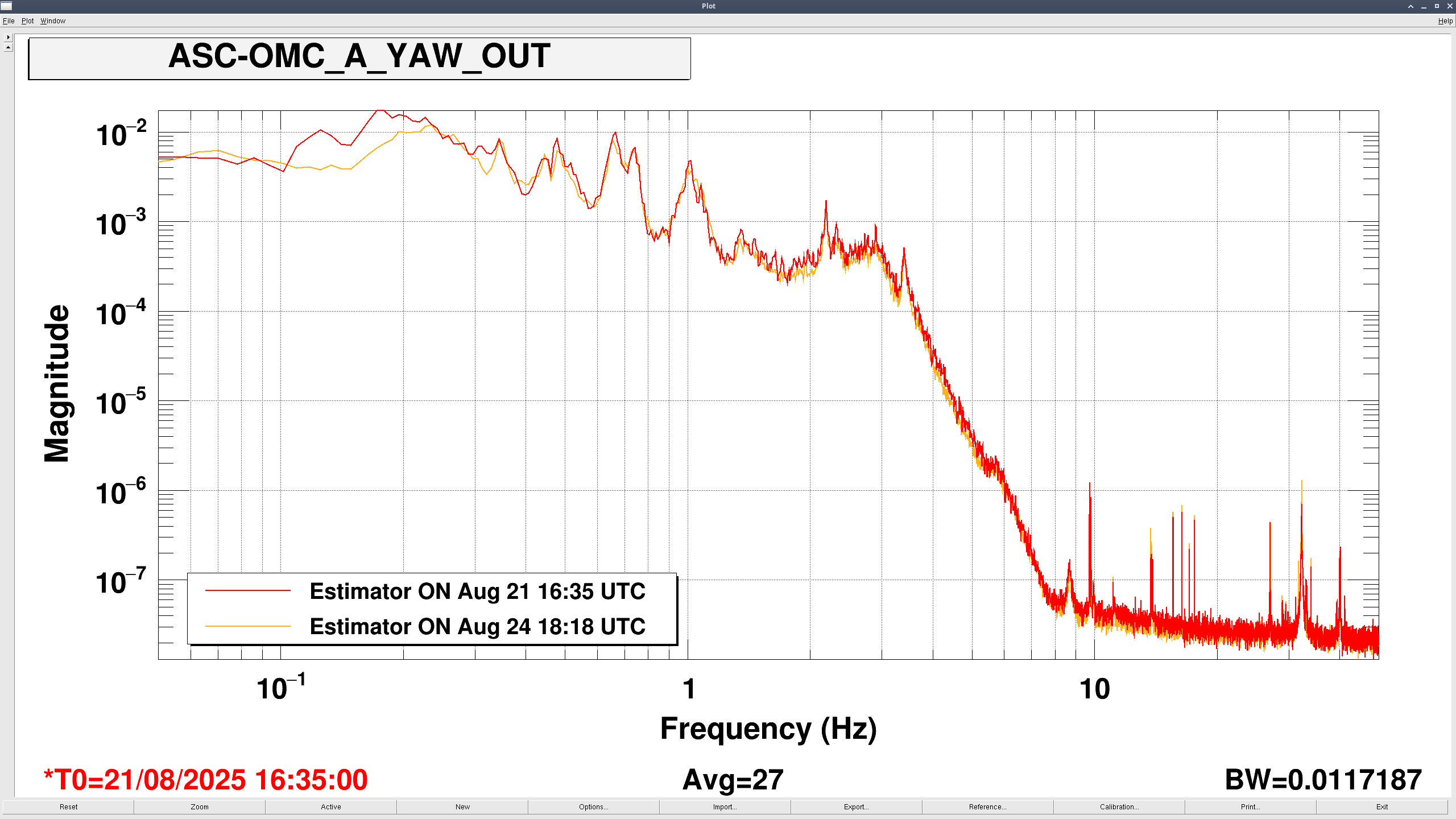
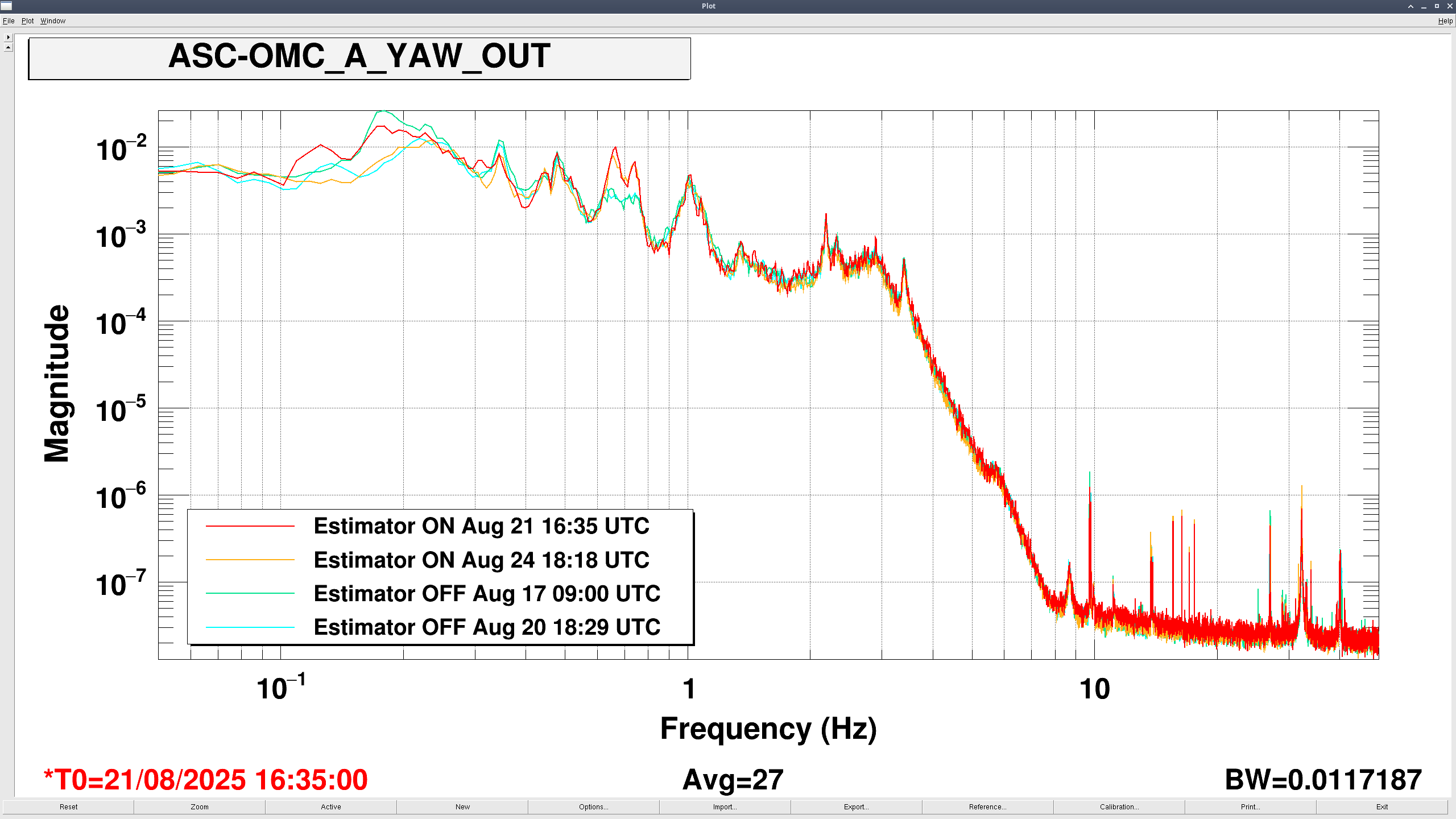
We used Brian's scripts to generate the blends for the PR3 OSEM estimator. We tuned these blends to the specific resonances of PR3 (which we expect to differ from SR3, as explored by Oli in [LHO: 86554]. We emphasized trying to match the bumps in the OSEM filter with the various resonances of the M1 to M1 plant [see in the figures attached].
The scripts used to create the filters, together with a script to load them into foton were updated to the SUS SVN inside 'sus/trunk/HLTS/Common/FilterDesign/Estimator'.
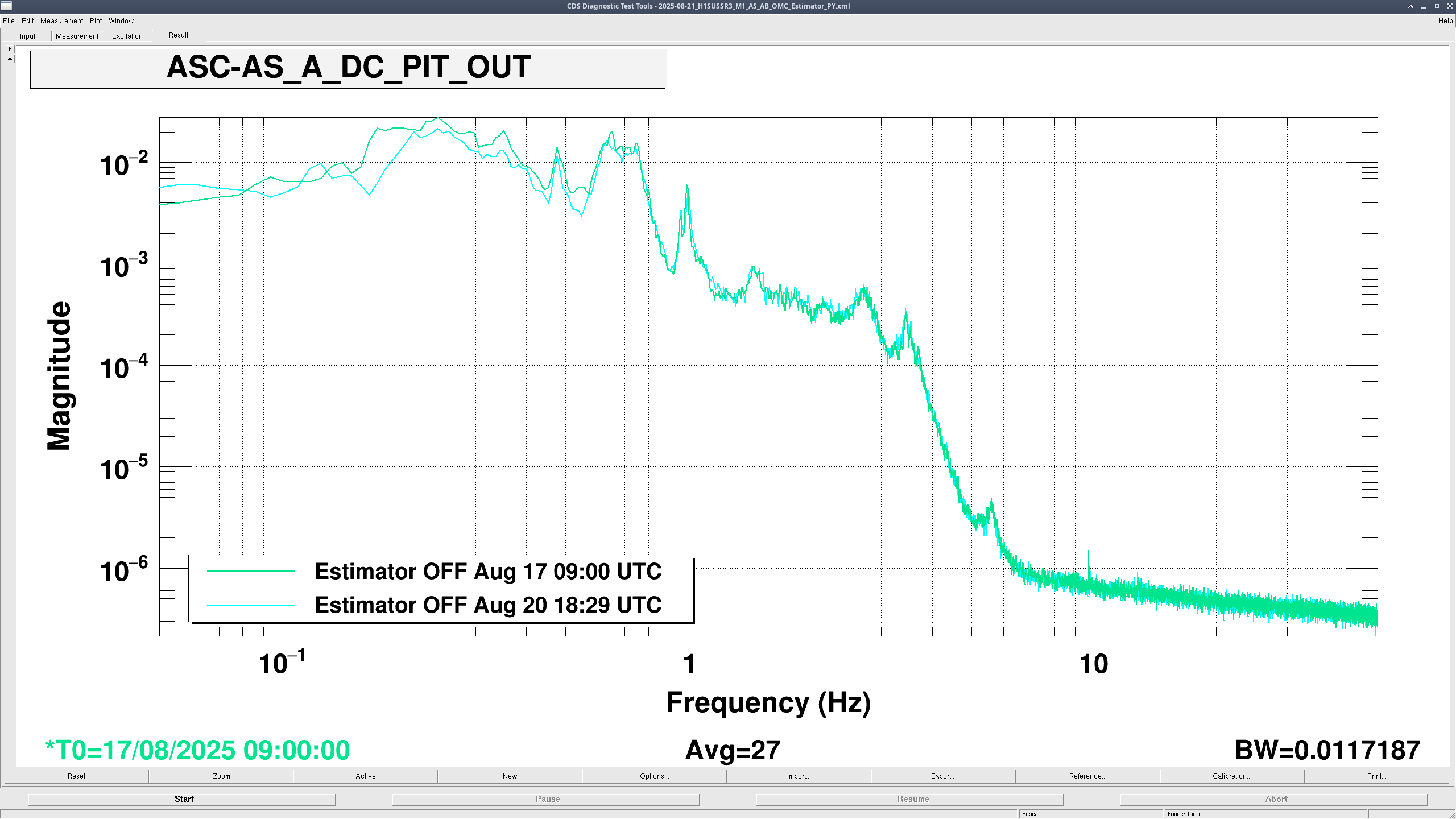
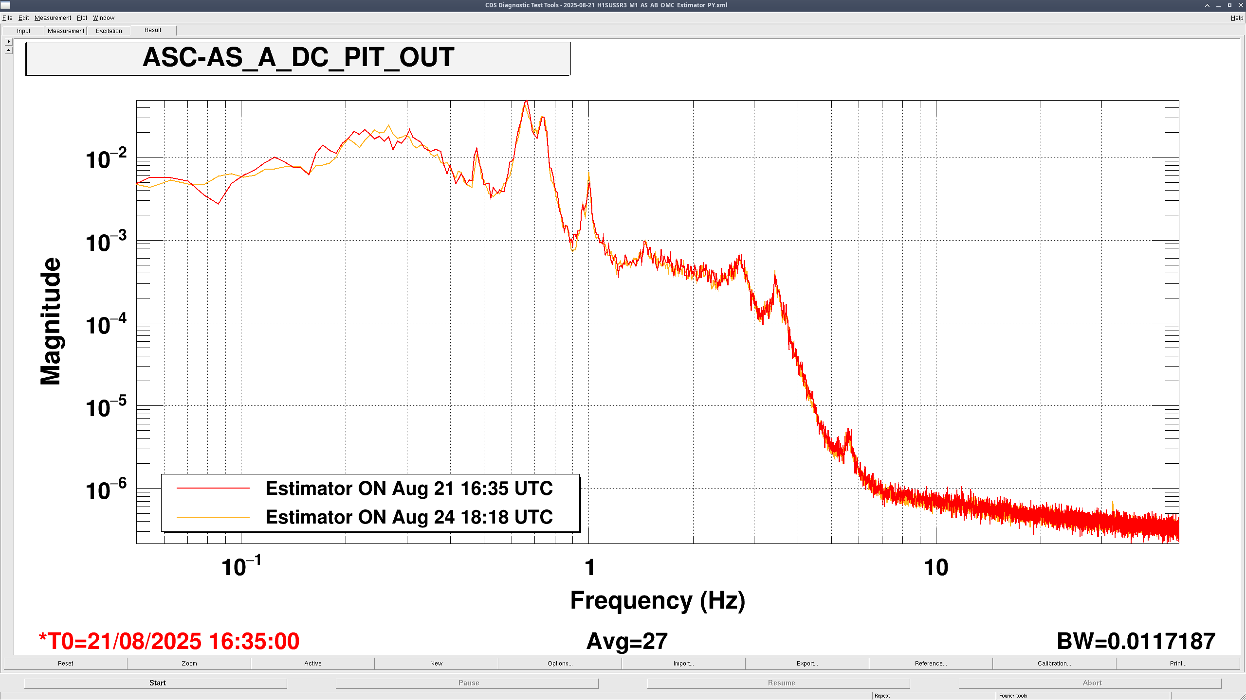
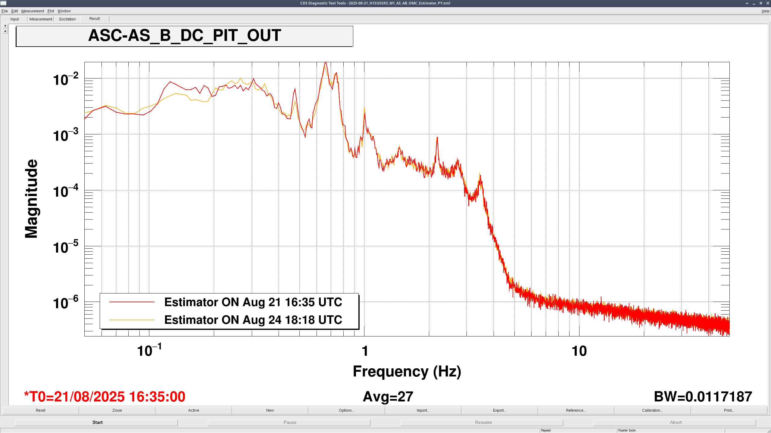
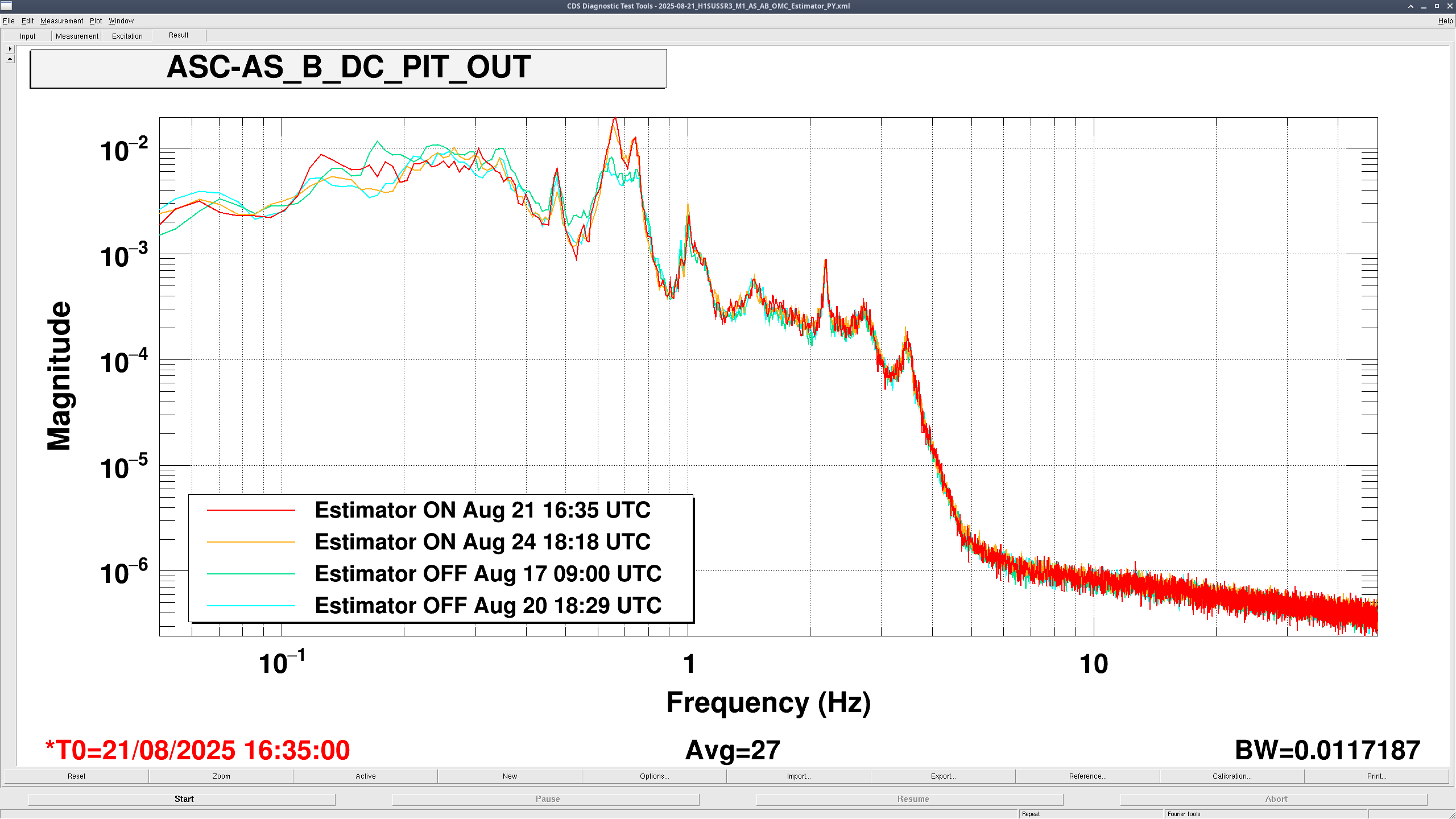
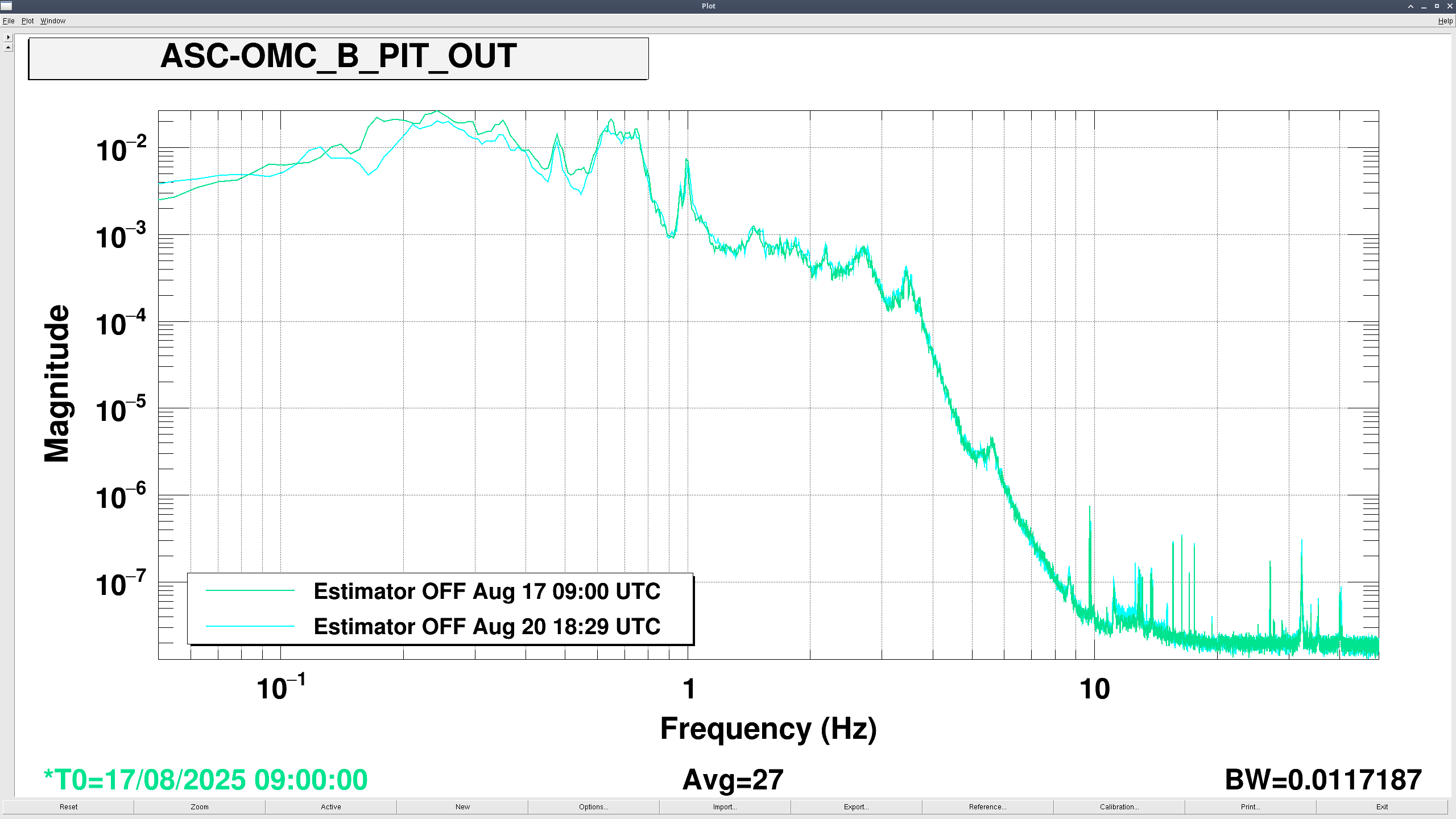
For pitch:
The pitch blends were created using 'blend_PR3_pitchv2.m' (see first pdf attached). The filters follow the same design principle as Brian did in [LHO: 86510] and [LHO:86452]. The blends are created by making the OSEM bandpass by adding an overall low-pass filter with four low-Q bumps that match the observed resonanced of the M1 to M1 plant. The high-frequency gain of this filter does not asymptote to zero to keep the phase of the bumps close to zero at the resonances of the modeled PR3 M1 to M1 plant, while not creating a zero in between bumps.
The zpks are:
model_filter =
'zpk([-0.083+22.156i,-0.083-22.156i,-0.097+13.118i,-0.097-13.118i,0,-0.037+4.136i,-0.037-4.136i,-0.045+4.738i,-0.045-4.738i],[-0.188,-0.171+4.106i,-0.171-4.106i,-0.199+4.771i,-0.199-4.771i,-0.438+13.125i,-0.438-13.125i,-0.37+22.177i,-0.37-22.177i],0.9)'
osem_filter =
'zpk([-1.807+20.726i,-1.807-20.726i,-2.733+10.99i,-2.733-10.99i,-8.429,-0.227+4.431i,-0.227-4.431i,-1.381+2.186i,-1.381-2.186i],[-0.188,-0.171+4.106i,-0.171-4.106i,-0.199+4.771i,-0.199-4.771i,-0.438+13.125i,-0.438-13.125i,-0.37+22.177i,-0.37-22.177i],0.1)'
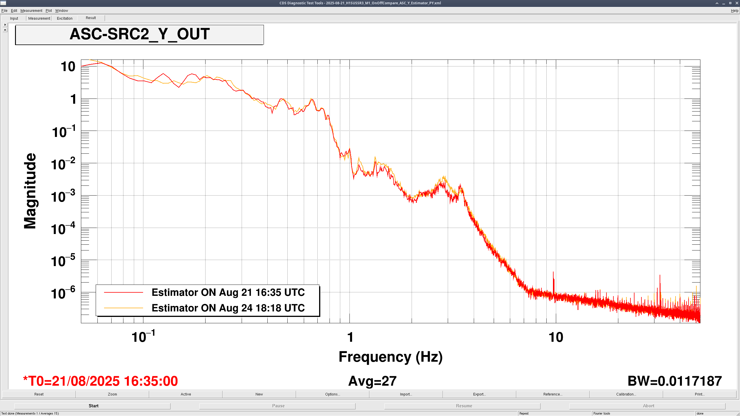
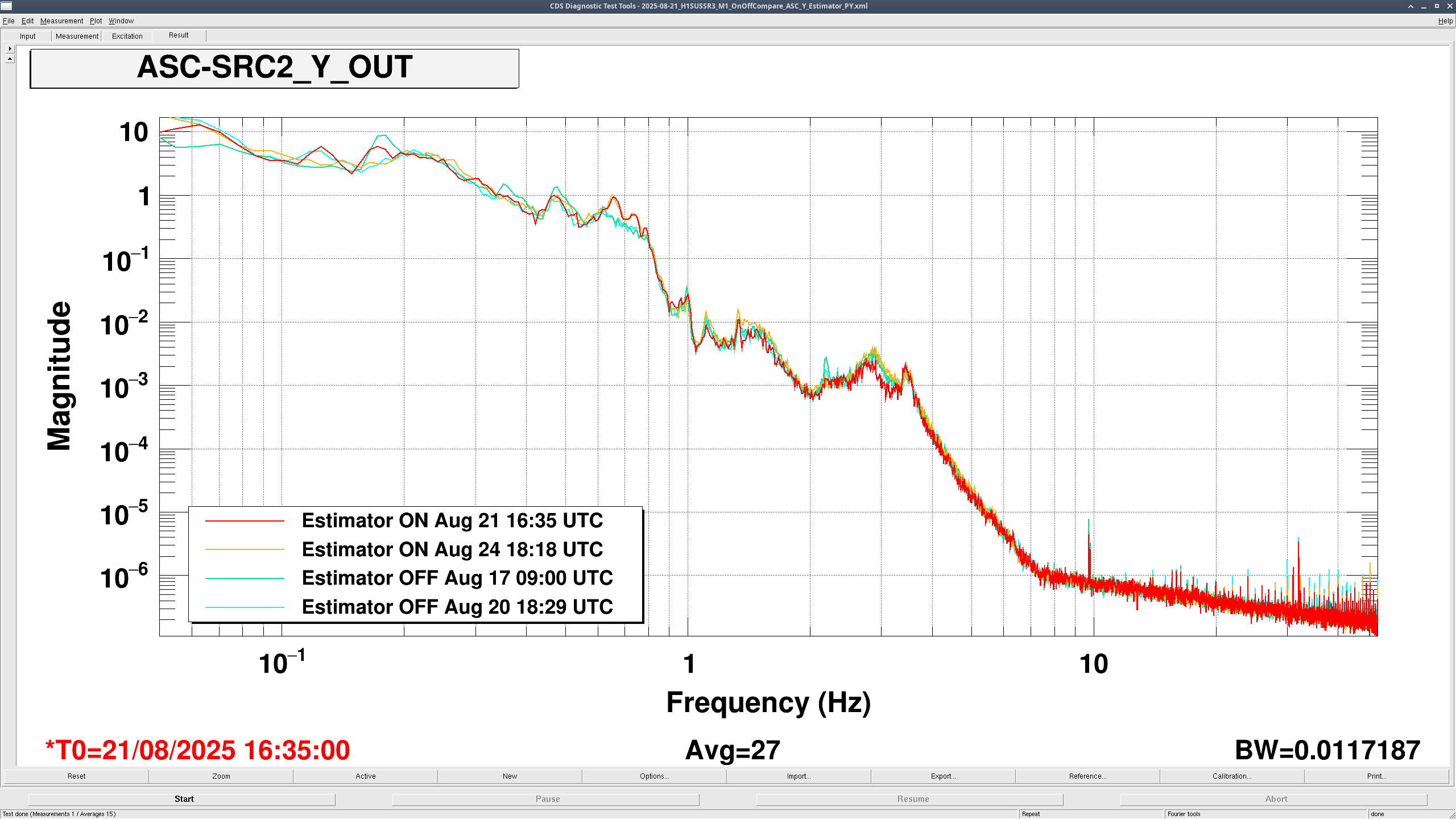
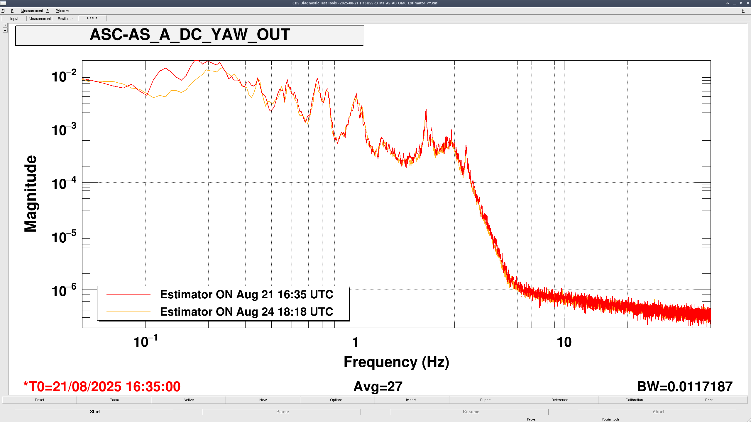
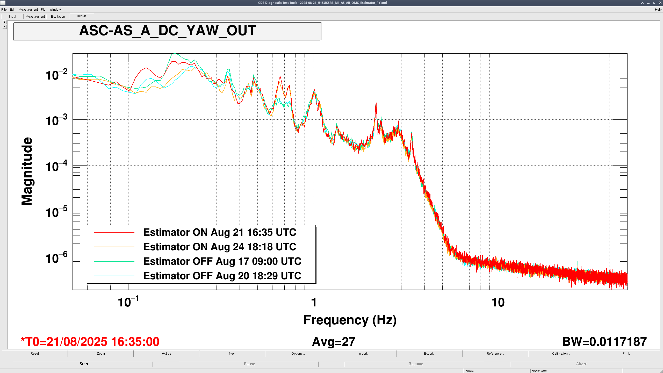
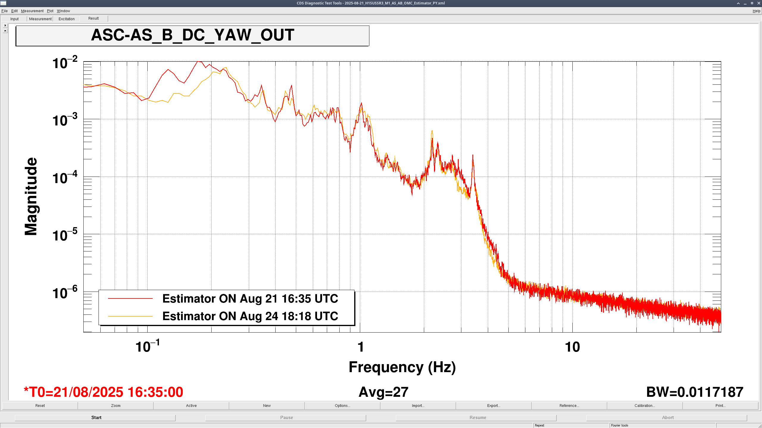
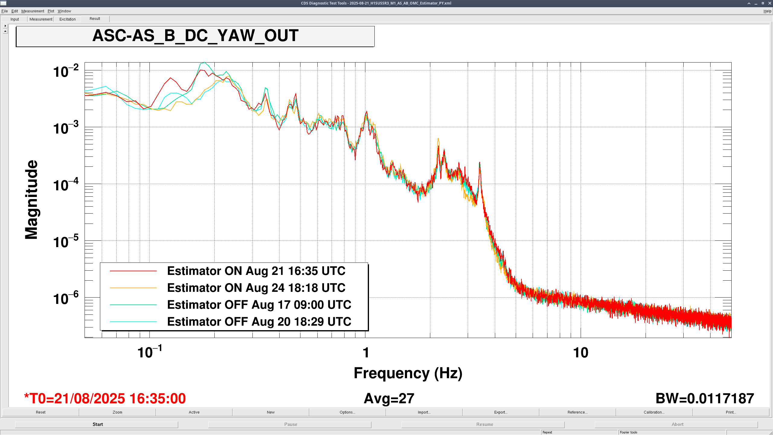
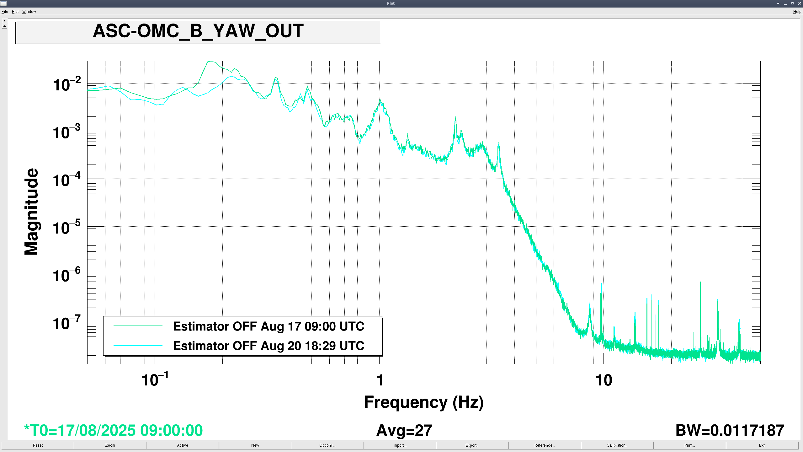
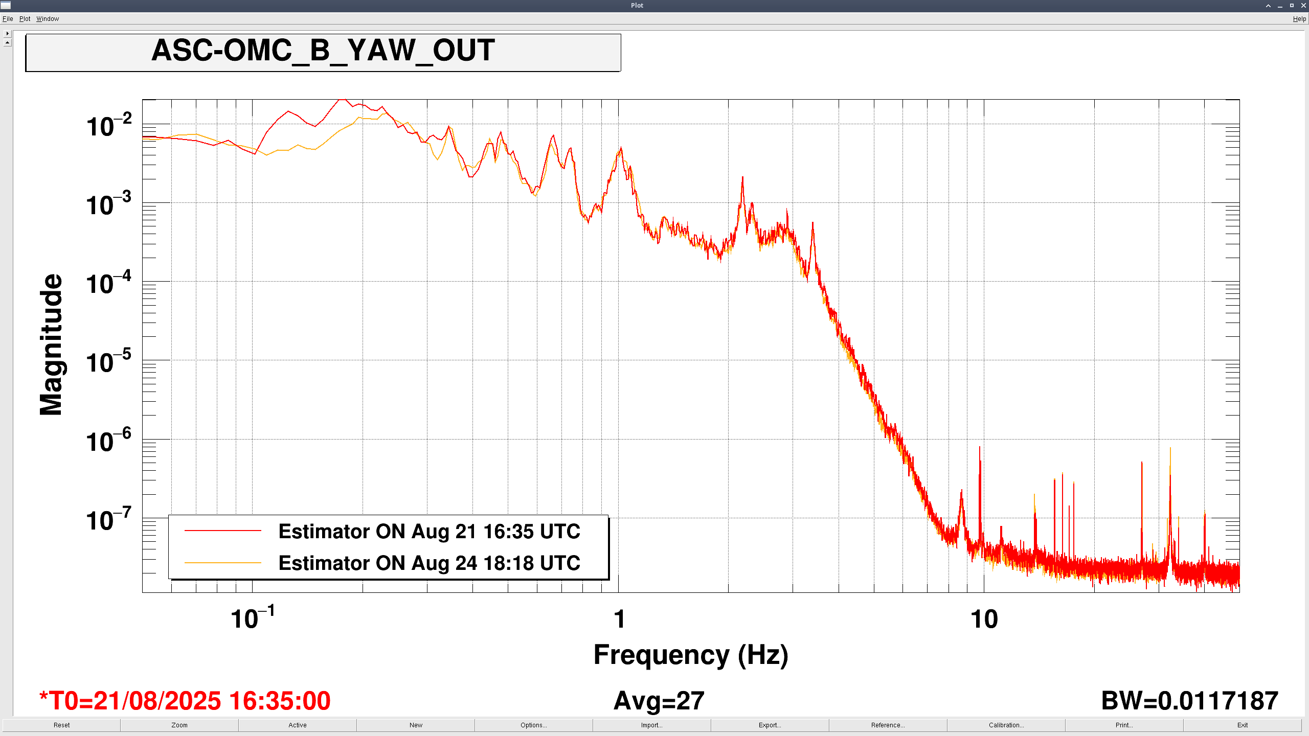
For yaw:
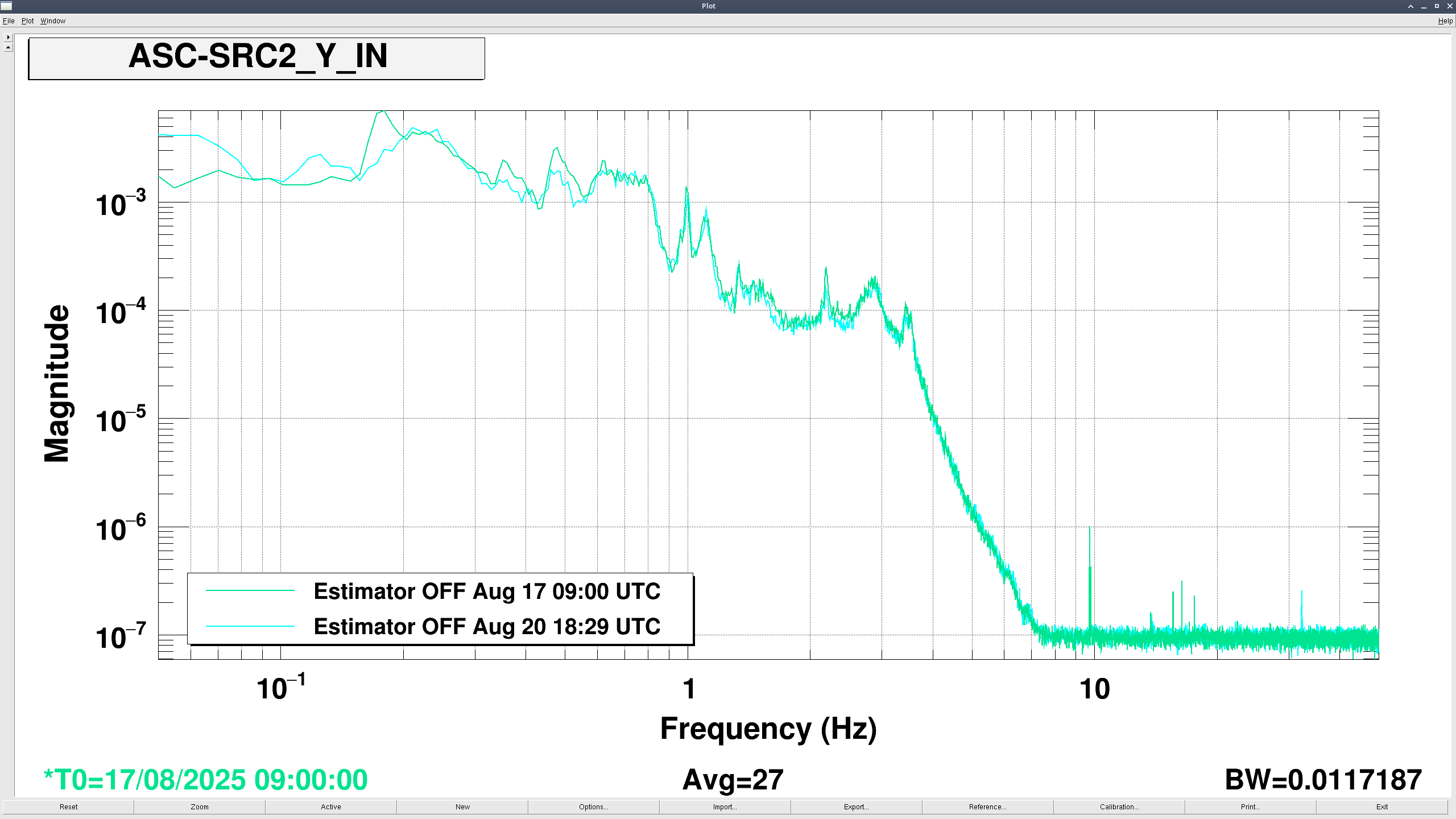
For the yaw estimator, we used 'Estimator_blend_skinnynotch_PR3yaw_20250825.m' which follows the design procedure on [LHO: 86265]. In this case the procedure is more similar to designing blends for the ISI: we pick a rolloff for the Highpass (model filter) and Lowpass (OSEM) filter, but add a few notches onto the model filter. Then by using the SEI SVN function 'maketruecomplements_tol' they are turned into complementary blends. The advantage of this process is that we can ensure the OSEM filter rolls off at high frequencies. One disadvantage is that it is a bit harder to tune the amplitude and phase of the OSEM blend around the suspension resonances.
The zpks are
model_filter =
'zpk([-0.306+21.389i,-0.306-21.389i,-0.242+14.516i,-0.242-14.516i,-0.128+6.404i,-0.128-6.404i,0],[-1.528-21.337i,-1.528+21.337i,-1.21-14.467i,-1.21+14.467i,-0.641-6.374i,-0.641+6.374i,-0.628],1)'
osem_filter =
'zpk([-0.81-18.387i,-0.81+18.387i,-0.473-9.928i,-0.473+9.928i,-0.216-3.503i,-0.216+3.503i],[-1.528-21.337i,-1.528+21.337i,-1.21-14.467i,-1.21+14.467i,-0.641-6.374i,-0.641+6.374i,-0.628],6.034)'


