J. Driggers, J. Kissel, L. Sun
We've made several advances in knowledge with today's collection of bi-weekly sensing function measurements:
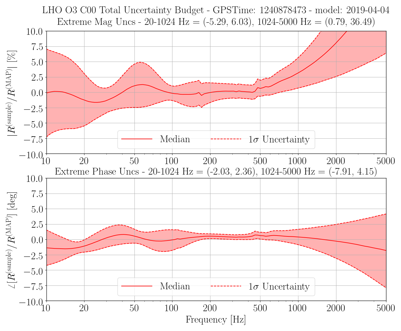
(1) I was able to successfully complete PCAL to DARM IN1 transfer functions out to 5 kHz with and extra template. It takes an extra 20 minutes. This data is still of poor quality, so it doesn't improve the estimate of response function systematic error *much* but it does a little. Pep and I continue to work on analyzing the roaming PCALX calibration line so we have better data quality up there and confirm our supposition that the error / uncertainty is not as large as is falsely reported by the Guassian Process Regression. Lilli will comment more on how much this high frequency data improves the uncertainty (spoiler: it's not much).
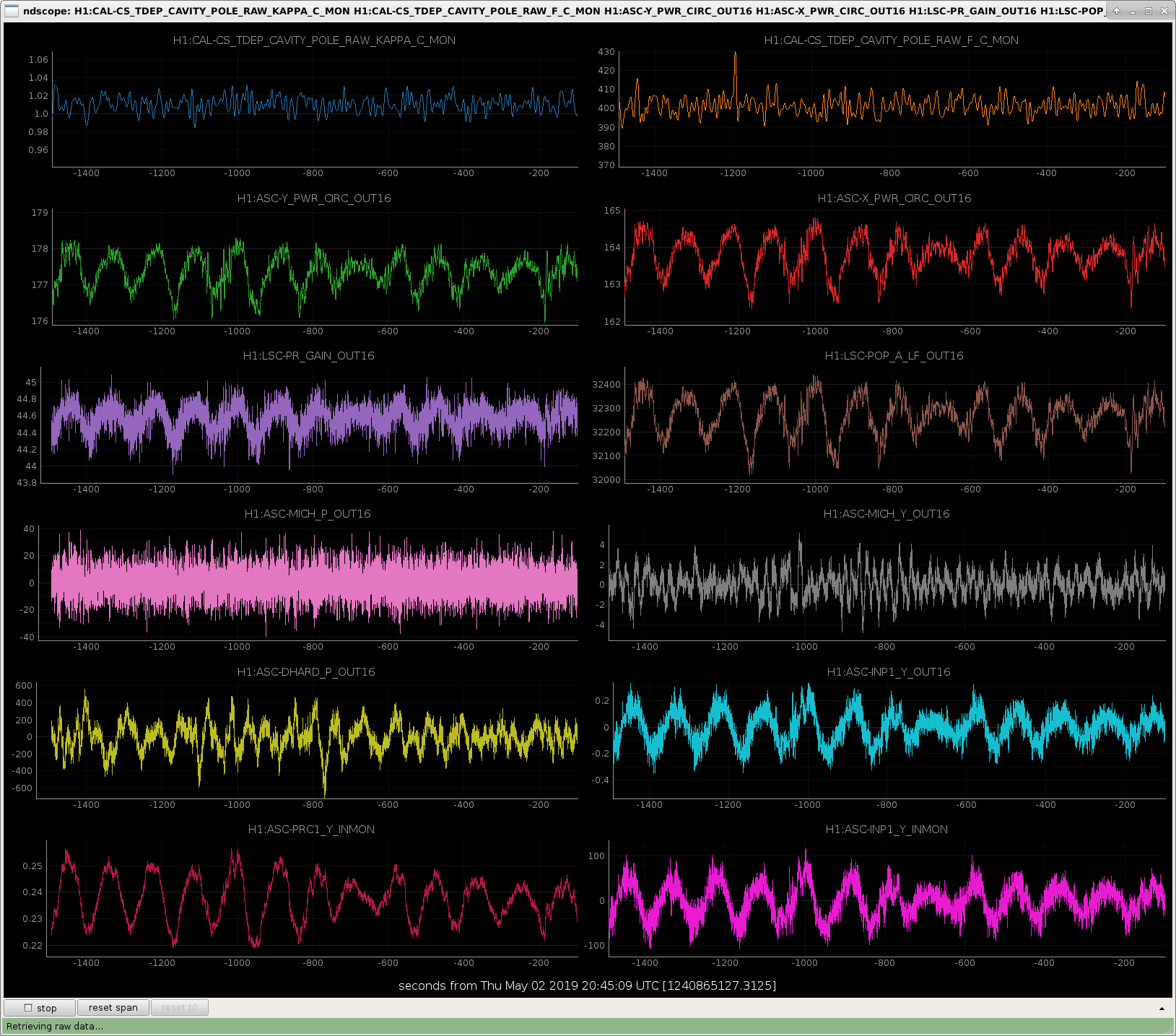
(2) We've been continuing to suffer from ~2 minute period oscillations in ASC that result in reported arm power fluctuations at the peak-to-peak of 2 kW (!!). A first attempt at re-phasing AS 38 (i.e. MICH ASC sensors) "fixed" it on Monday for the overnight long lock stretch (LHO aLOG 48857), but that phase change was reverted after failing at to re-acuire lock after Tuesday maintenance (LHO aLOG 48878). Jenne adjusted the phase just before I began measuring today, but (unknowingly at the time) was using the wrong metric. Thus, these sensing function measurements may be corrupted by the oddball phasing of AS36, because the oscillations would come and go during my sweeps.
Evidence points toward us needing to dynamically change the WFS phase, having one setting for lock-acquisition, and another after the IFO has thermalized. Jenne has written m,ore on this in LHO aLOG 48948.
(3) In that semi-stable, some-times oscillating configuration, with the oddball phasing, apparently, the DARM optical plant changed. The most significant change is that the SRC optical spring frequency changed from the reference 4.5 Hz to a lower 2.3 Hz. The DARM coupled cavity pole reduced from 410 to 405 Hz, and the optical gain increased by 1%. Jenne has re-rephased the AS36 WFS *after* I've taken this data, so I want to re-confirm with more measurements in this new-new AS36 WFS phase configuration before I set off the "we need to change the reference model" alarm bells.
(4) Unfortunately, even though it's dreadfully obvious that an arm power fluctuation at the 2 / 170 = 0.011 = 1% level should be reported in the time-dependent correction factor for the optical gain, kappa_C, we see no such reported fluctuation in these TDCFs. We also see no such fluctuation reported in the DARM coupled cavity pole, f_cc. This is likely because the fluctuation is faster than the integration / average time of the calibration lines (currently 13 averages of 10 sec FFTs, i.e. effectively only giving an update every 2 minutes, and thus this two minute period oscillation is averaged away)
Below are details about the data, and how we've processed it in order to come to these conclusions.
Attached are three plots:
(a) 2019-05-02_H1IFO_OpticalPlant_Fluctuations.png A trend showing the supposed time-dependent correction factors for the optical plant against arm powers and various ASC control / error signals that show the same behavior. (Remember, because the optical spring still has unphysical phase rotation at low frequency, the tracking of the optical spring parameters are bogus, and thus have been turned off in the real time system).
(b) 2019-05-02_H1_sensingFunction_noMCMCTDCFcorr.pdf A collection of plots of the processed sensing function *if the measurement is not corrected for any time dependence* where the time dependence is measured by the ratio of MCMC fit values (i.e. not from estimates of those values from calibration lines).
(c) 2019-05-02_H1_sensingFunction_withMCMCTDCFcorr.pdf The same collection of plots, but now correcting the measurement for the MCMC values from (b), and thus "propagating it back in time" to the reference values.
One can see from (b), and specifically page 5, that today's data set is definitely an outlier -- all other days have not been corrected for anything. Similarly, looking at pages 3 and 4, comparing the reference model against today's measurement leaves a large residual, and "screws up" the Gaussian Process Regression, or rather, the GPR is accurately reporting large systematic error.
Once we correct the measurement for the difference in MCMC parameters, the results in (c) show things clean up better.
Again, we should not create a new model, nor update any of the low-latency data stream yet. We should gather more data, as we continue to settle on a ASC configuration to combat this oscillation issue.
%%%%%%%%%%% Details %%%%%%%%%%%%
2019-04-04 Reference Model Parameters are from LHO aLOG 48378.
The detailed answers from the MCMC fit of the *uncorrected* data are as follows:
2019-04-04 2019-05-02
Reference New Values
Overall gain, H_c (ct/m) | 3.250e+06 3.281e+06 (+1490,-1382) or (+0.0454%,-0.04213%)
Cavity pole, f_cc (Hz) | 410.6 404.3 (+0.4895,-0.5211) or (+0.1211%,-0.1289%)
Detuned SRC spring frequency, f_s (Hz) | 4.468j 2.269 (+0.1046,-0.1181) or (+4.611%,-5.205%)
Detuned SRC spring quality factor, Q_s () | 52.14 94.15 (+902.2,-2156) or (+10.44%,-4.368%)
Residual time delay, tau_c (usec) | 1.0 0.9597 (+0.2495,-0.2655) or (+ 26%,-27.66%)
The resulting TDCFs from the comparing the above new MCMC results against the reference model:
kappa_c = 1.009538 (New Value / Reference Value)
f_cc = 405.1 (New Value)
f_s = 2.292j (New Value, entered as complex)
Q = 94.18 (New Value)
Because we've yet to figure out a good system for correcting sweep measurements for time dependence, these have been added to the list of hard-coded corrections in
^/trunk/Common/pyDARM/src/sensing.py
and we chose to either invoke them, or not invoke them in the following analysis scripts, used to process today's data:
^/trunk/Runs/O3/H1/Scripts/FullIFOSensingTFs/process_sensingmeas_20190502.py
^/trunk/Runs/O3/H1/Scripts/Uncertainty/process_allmeas_writeGPRHDF5_20190502.py
and those scripts have been committed to the repo.
The data from today lives here:
^/trunk/Runs/O3/H1/Measurements/FullIFOSensingTFs/
2019-05-02_H1_DARM_OLGTF_LF_SS_5to1100Hz_15min.xml
2019-05-02_H1_PCAL2DARMTF_BB_aftersweeps.xml
2019-05-02_H1_PCAL2DARMTF_BB.xml
2019-05-02_H1_PCAL2DARMTF_HF_SS_600to5000Hz_15min.xml
2019-05-02_H1_PCAL2DARMTF_LF_SS_5t1100Hz_10min.xml
There are broad band sweeps "in the can" before the measurements started (though after Jenne phased the AS36 WFS), and after the measurements were complete (but before Jenne re-re-phased the WFS with a better metric). They show no evidence time dependence during the measurement, so I've not processed them in any more detail.
You'll note there are LF and HF templates for the PCAL2DARMTF. That data was exported and *by hand* stitched together to create the data shown in the attached plots. Those stitched together .txt files are
^/trunk/Runs/O3/H1/Measurements/FullIFOSensingTFs/
2019-05-02_H1_DARM_OLGTF_Stitch_SS_A_DARMIN2_B_DARMEXC_coh.txt
2019-05-02_H1_DARM_OLGTF_Stitch_SS_A_DARMIN2_B_DARMEXC_tf.txt
2019-05-02_H1_PCAL2DARMTF_Stitch_SS_A_PCALYRX_B_DARMIN1_coh.txt
2019-05-02_H1_PCAL2DARMTF_Stitch_SS_A_PCALYRX_B_DARMIN1_tf.txt
We should figure out a better way to merge this data.
Including the high freq data points can improve the systematic error from 7.5% (second figure) to 5% (first figure) at ~2kHz.
This is obtained by using the multi-measurement GPR including the time dependence corrected 0502 measurement (page 6 in Jeff's 2nd attachment).
The dots on the first plot indicate the corrected sweep measurement taken today. Due to the questionable data quality, we have not included it in the latest uncertainty estimate. This plot here shows the slight improvement at high frequency with only a few poor data points. We expect further improvement when more measurements at high frequencies are available.
About an hour and a half after lock acquisition we were still getting the yaw ASC oscillations. I looked at moving MICH ASC to the AS 72 MHz signals (which are in use for SRC alignment), but there is very little signal there. I did get a single-frequency transfer coefficient by driving BS in pitch quite hard and tried blending the RF72 signal in with the RF36 signal (with the idea of trying to turn off the RF36), but the noise increase in MICH ASC was quite dramatic. I unblended, and left MICH ASC on the nominal AS_A_RF36_Q signals.
I then moved the phase of AS_A_36 and watched the ASC yaw oscillations and circulating power buildups, and ended up with an answer 5 degrees different than Georgia's (alog 48857) when she checked the phase in full lock. This is good, although not so great if we can't reacquire lock with this phasing.
I also tried moving the SRC1 offsets in both pitch and yaw to see if I could further improve any buildups or the cavity pole. In the end, having no offsets seemed to be pretty close to the best I could find.
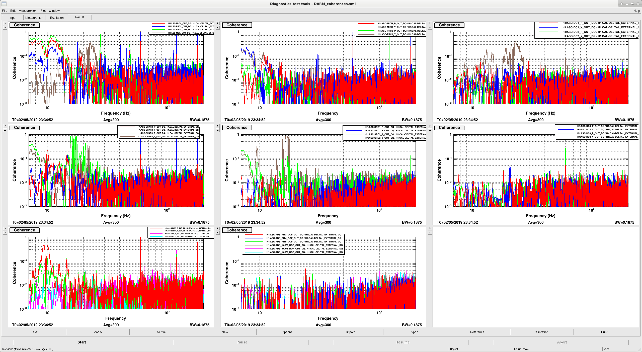
I see that the noise between 20 Hz and 30 Hz is slightly elevated, very similar to what Andy pointed out in alog 48881 after Georgia initially rephased AS 36 on Monday. I ran A2L on ITMX just in case it was some slight change in spot position on that optic, but that didn't improve things. I looked at Andy's bruco, but it shows coherences with REFL WFS signals, which I don't really see right now when I look at a dtt version of coherences (see attached figure). I do see coherence with LSC-MCL, which is a little bit surprising. And, we still have the old friend DC2 Yaw.
z write H1:ASC-AS_A_RF36_SEG1_PHASE_R -175 H1:ASC-AS_A_RF36_SEG2_PHASE_R -190 H1:ASC-AS_A_RF36_SEG3_PHASE_R -170 H1:ASC-AS_A_RF36_SEG4_PHASE_R -175
Once we're locked, after about an hour and a half you'll likely see ASC yaw oscillations (most noticeably in the blue INP1 trace on nuc6). When this happens, copy the following into a terminal:
z step H1:ASC-AS_A_RF36_SEG1_PHASE_R +1,40 H1:ASC-AS_A_RF36_SEG2_PHASE_R +1,40 H1:ASC-AS_A_RF36_SEG3_PHASE_R +1,40 H1:ASC-AS_A_RF36_SEG4_PHASE_R +1,40 -s 1
This should step each segment's phase up by 1 degree, 40 times, with 1 second waits between each step. So, this will require about 1 minute out of observing time, but will help the IFO be more stable.
Can the RF36 phase change be deduced from the SUM channels, ie. atan (Q/I)?
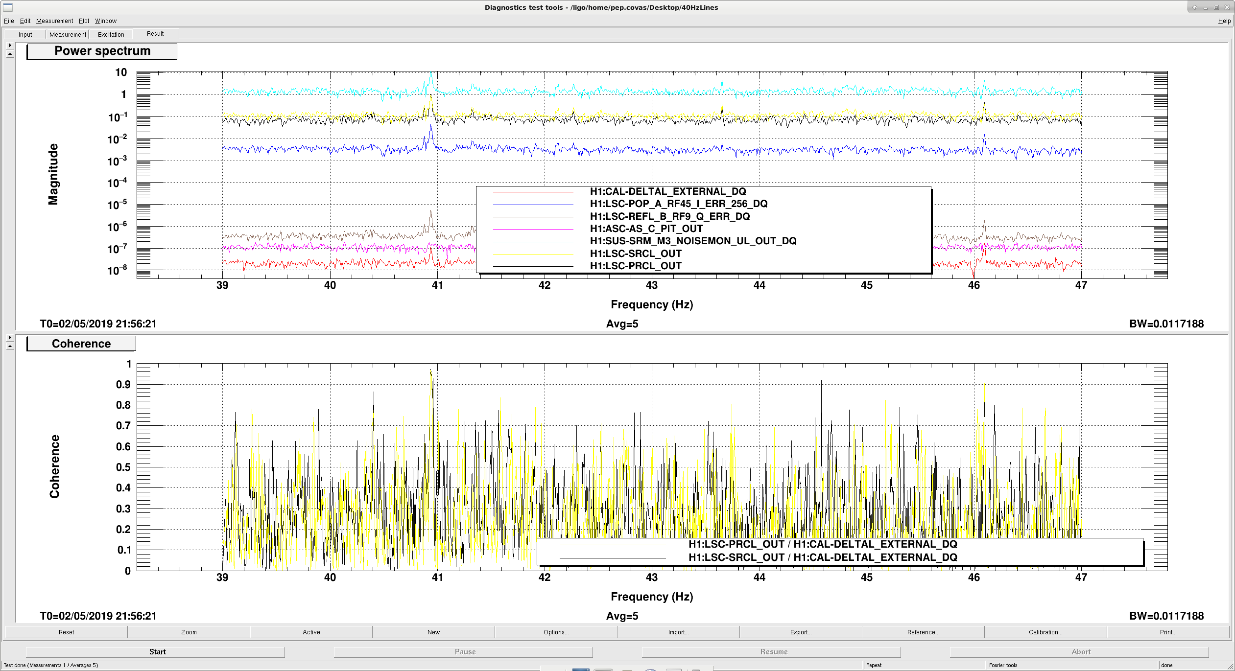
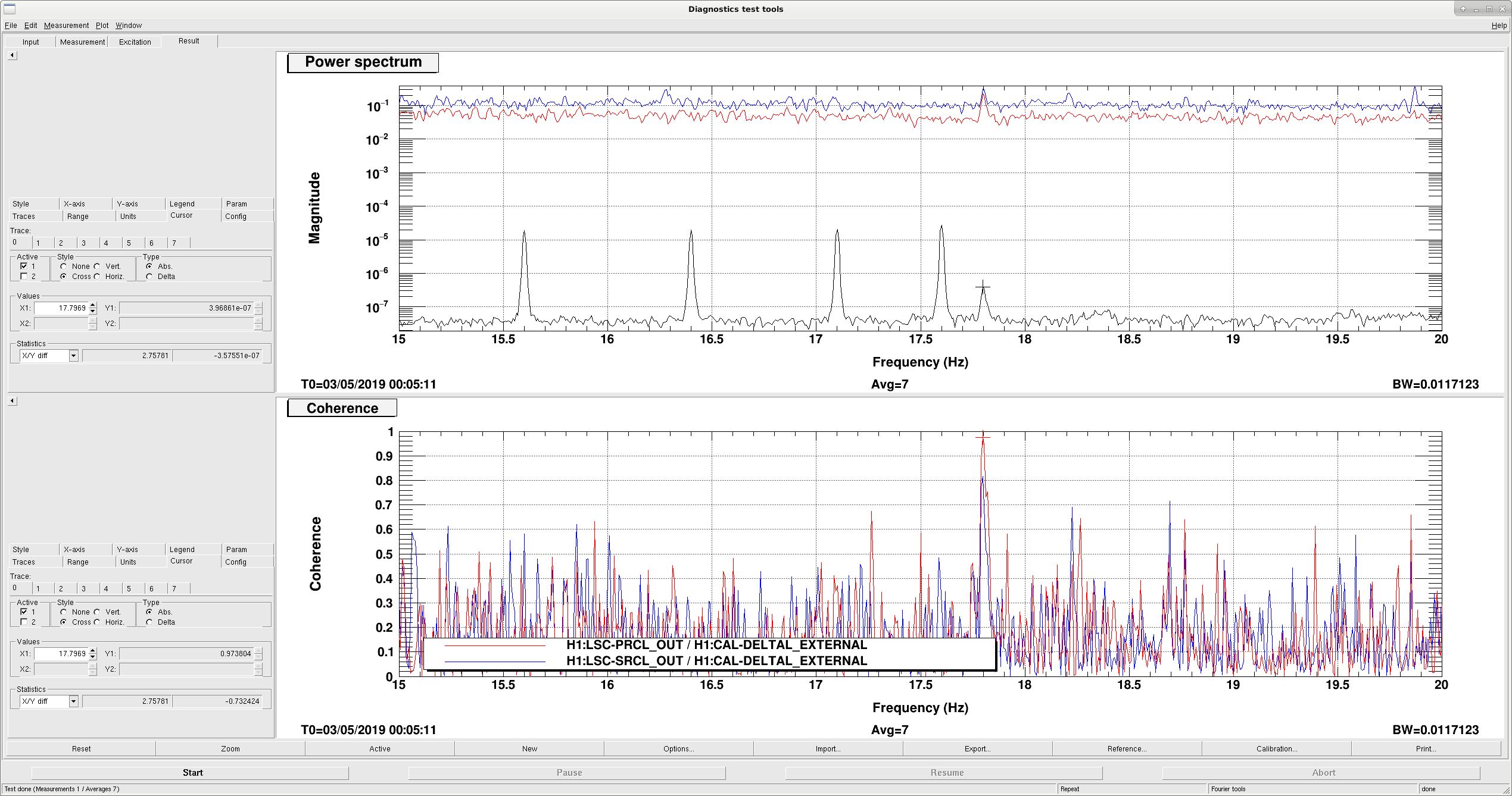
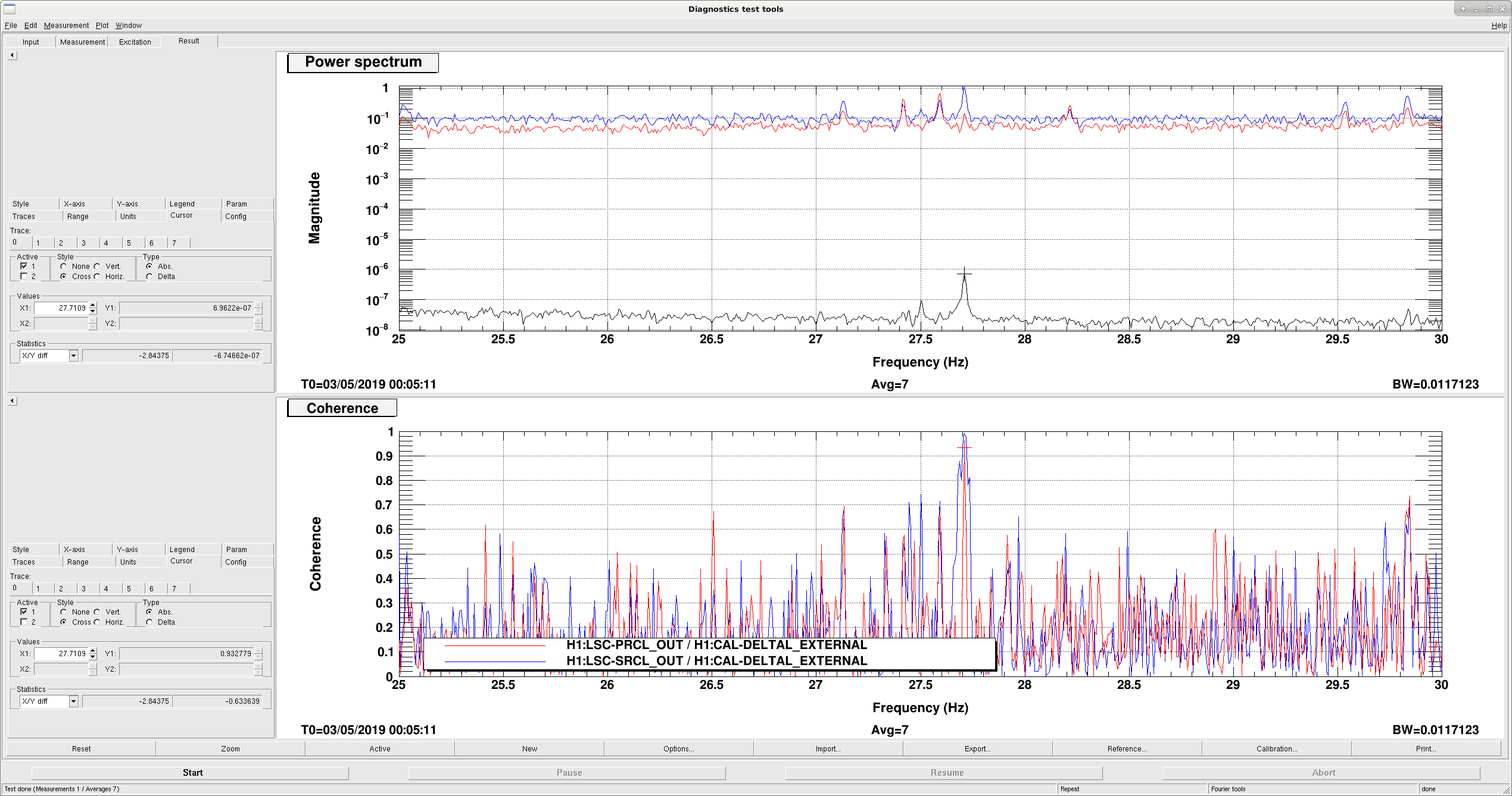
After running another bruco analysis (https://ldas-jobs.ligo-wa.caltech.edu/~pep.covas/bruco/1240824092/) I found coherence around these two lines with several channels related to SRM and PRM.
I found these lines in the coil driver monitors of PRM and SRM, and also in some sensors like LSC-REFL_A_RF45_I_ERR_DQ and LSC-REFL_B_RF9_Q_ERR_DQ. I traced these signals back to the controls signals of the loop LSC-SRCL_OUT and LSC-PRCL_OUT, which also show increased coherence around these frequencies.
I checked more channels with DTT, and apparently these lines are there for LSC signals, but not ASC signals. Jeff has suggested that some notches around these frequencies could be applied to the LSC loops in order to suppress these lines.
TITLE: 05/02 Day Shift: 15:00-23:00 UTC (08:00-16:00 PST), all times posted in UTC
STATE of H1: Observing at 108Mpc
INCOMING OPERATOR: Jim
SHIFT SUMMARY:In and out of observing for calibration measurements and commission to fix the recent ASC Y oscillation.
LOG:
1515 Bubba and Chandra checking inside the beamtube enclosure just before MX
1605 Jenne, Sharan to LVEA to toggle noise eater
1632 Observing
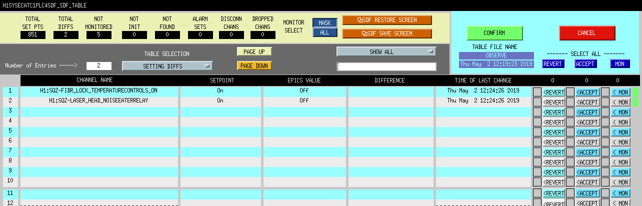
1732 Out of Observing from SDF diff caused by accidental click
1733 Observing
1752 Kyle to MY
1800 Out of Observing for calibration
1804 Kyle back
1814 Bubba, Chris to EY to check on air handlers
1835 Bubba, Chris back
1840 Christina to MY
1925 Observing
2132 Out of Observing to make change for ASC oscillation
2244 Observing
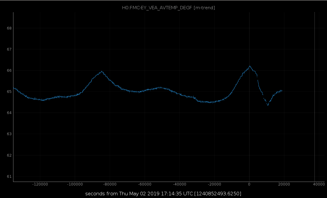
At ~ 1015 hrs local time, I got an alarm that the temperature at E Y was ~ 1 degree F. above set point. I started to investigate and things were just not looking correct on my FMCS screen. I confirmed with the control room operator that I was able to go to the end station and upon entering the building, I immediately noticed the sound was not what it normally is. I looked in the air handler room and the F/B damper was completely closed. I looked at the linkage which was in an obvious bind so I forced the damper open and the temperature immediately started to stabilize. I will continue to closely monitor the temps and hope to re-adjust the linkage on Tuesday morning unless it is needed sooner.
Back to Observing 1925 UTC.
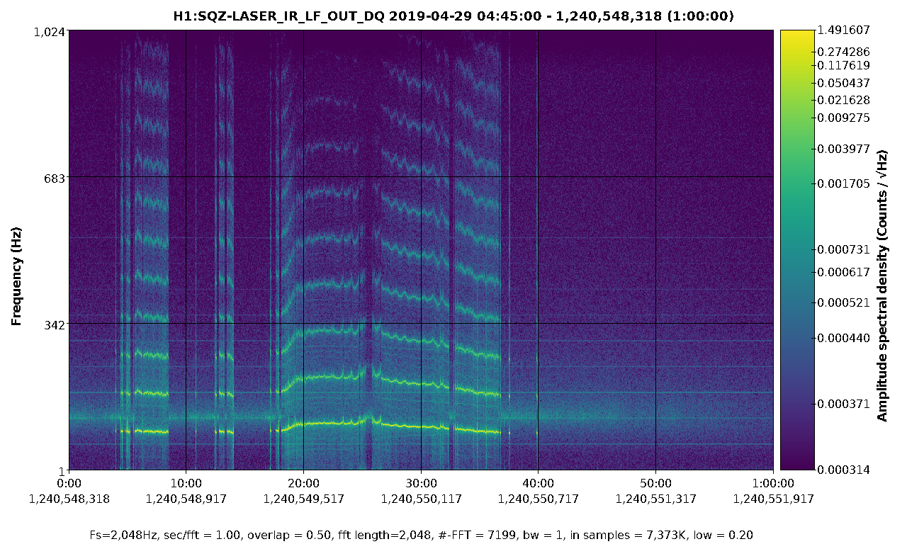
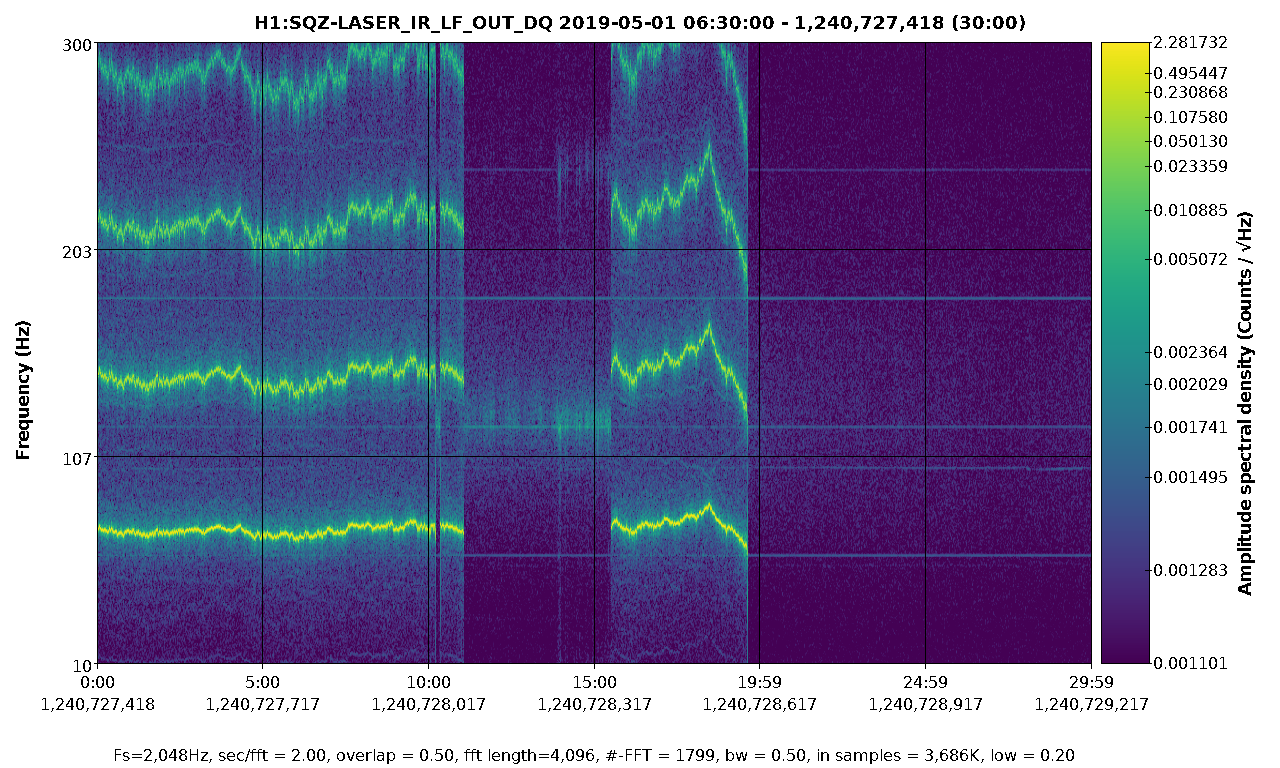
While we were out we tested turning on and off the SQZ noise eater. It clearly made the ~103Hz line come up and disappeared. So, we left it off and the associated SDF is attached.
TJ, Andy, Josh
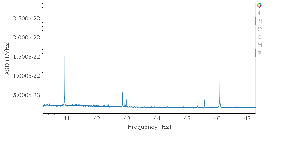
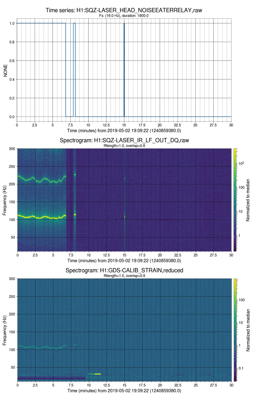
For visualization purposes, we lined up the noise eater toggle with a spectrogram of the SQZ laser and h(t). The state switches line up perfectly and the wandering line in h(t) disappears when the noise eater is switched off.
See attached time series and spectrograms.
[Bubba, Chandra]
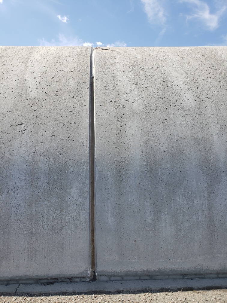
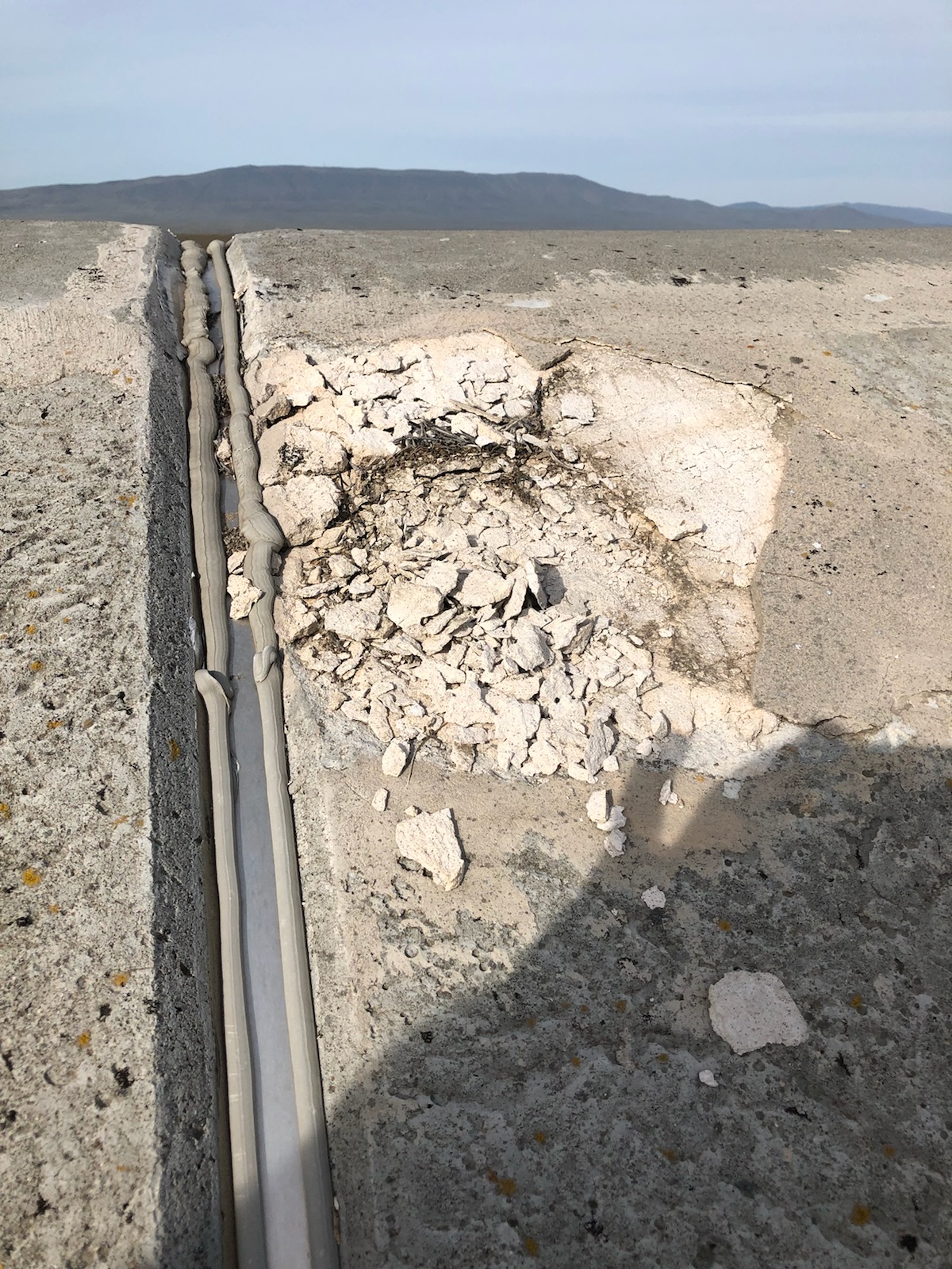
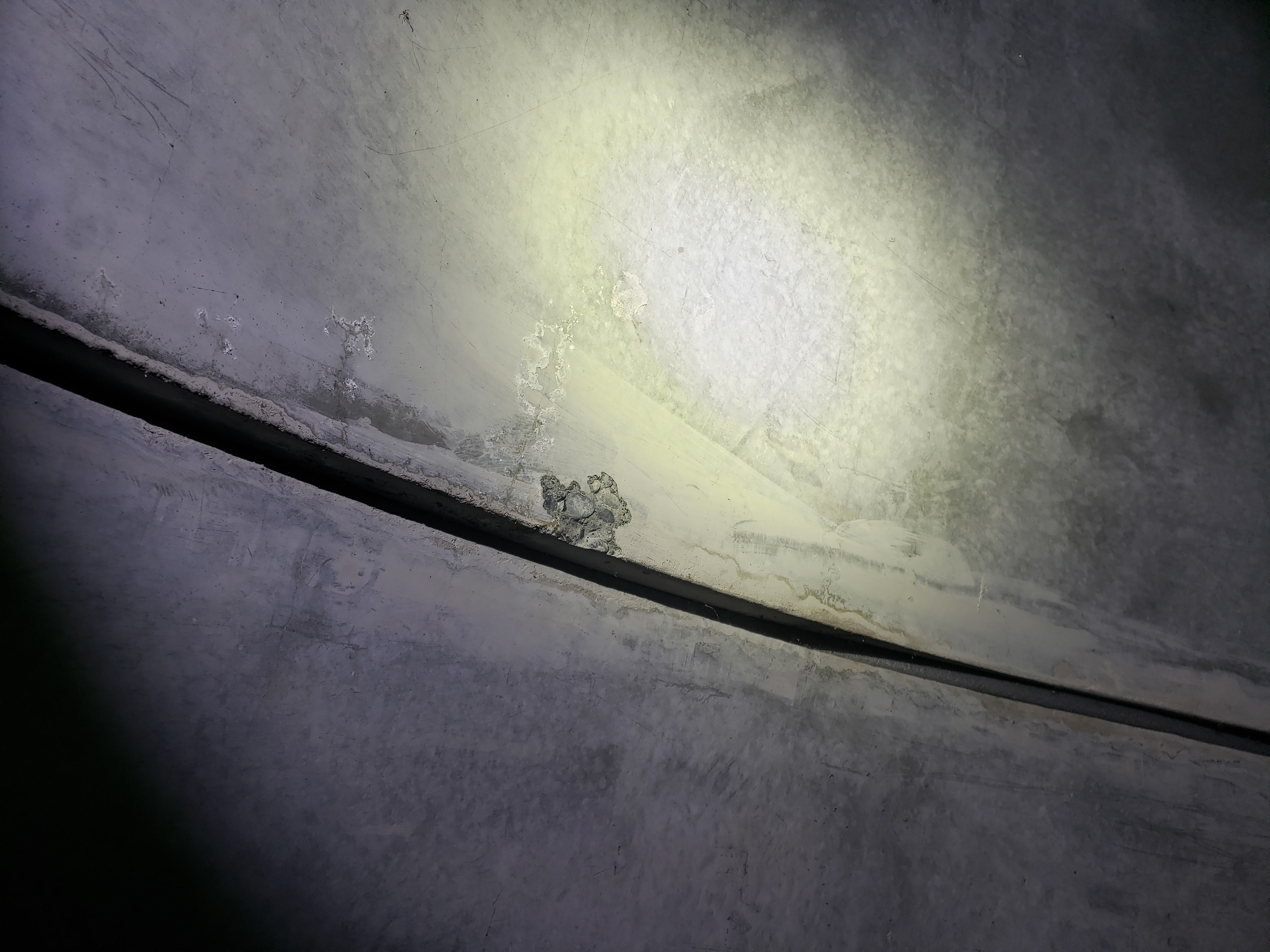
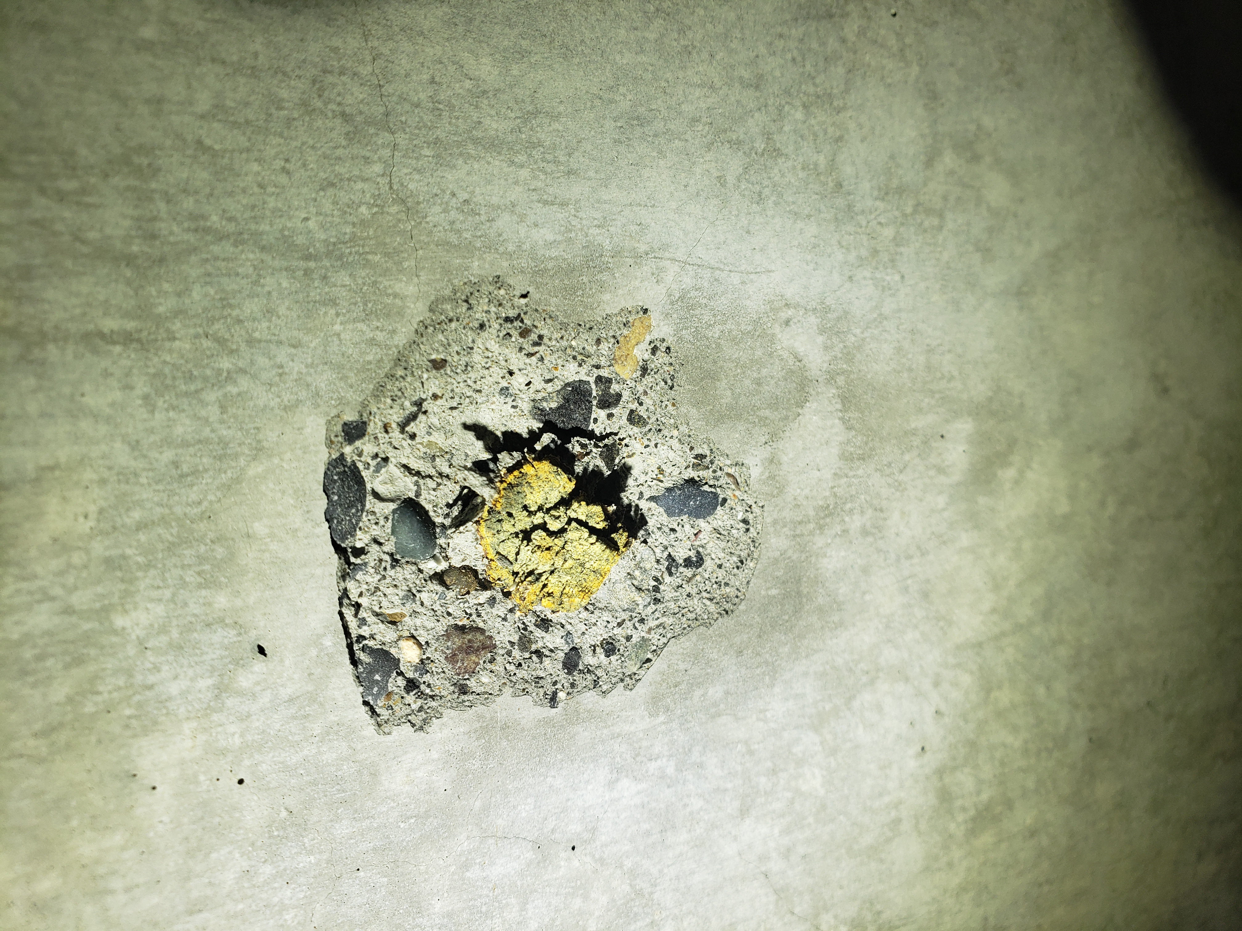
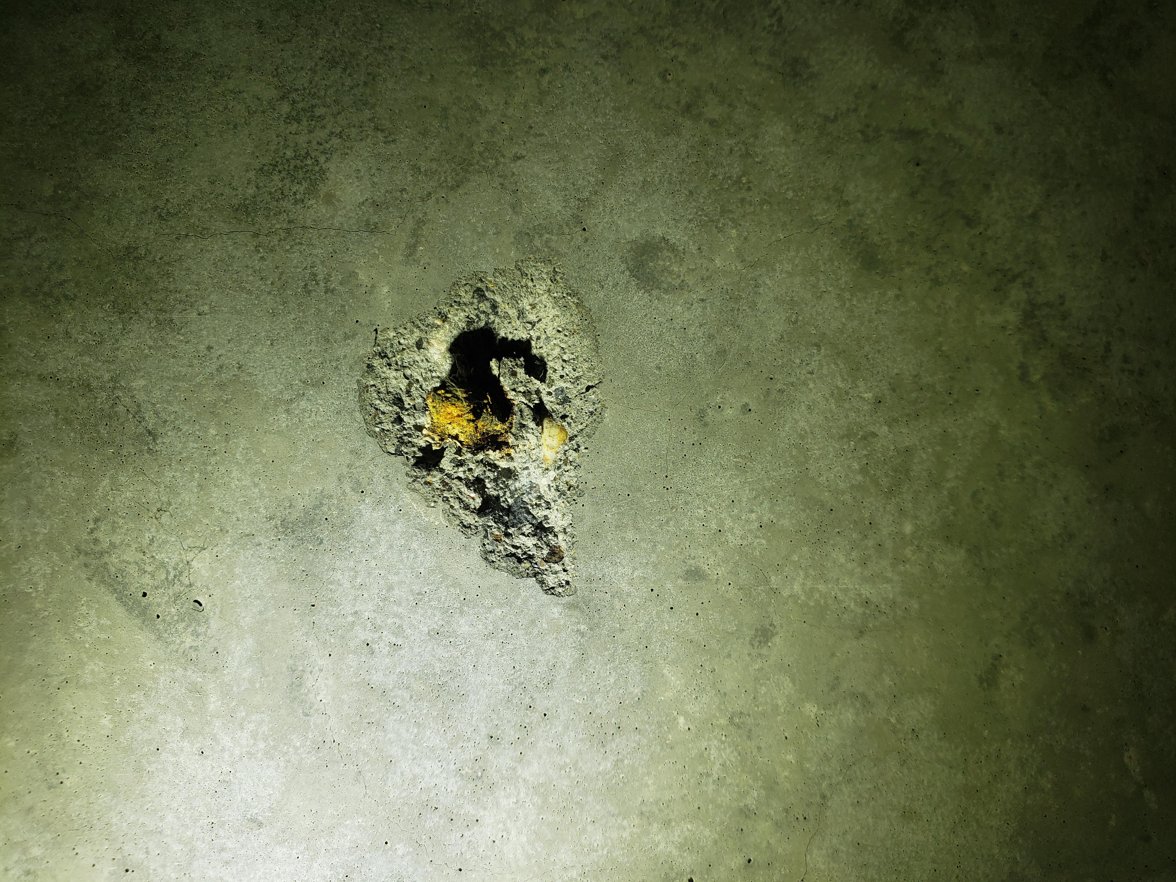
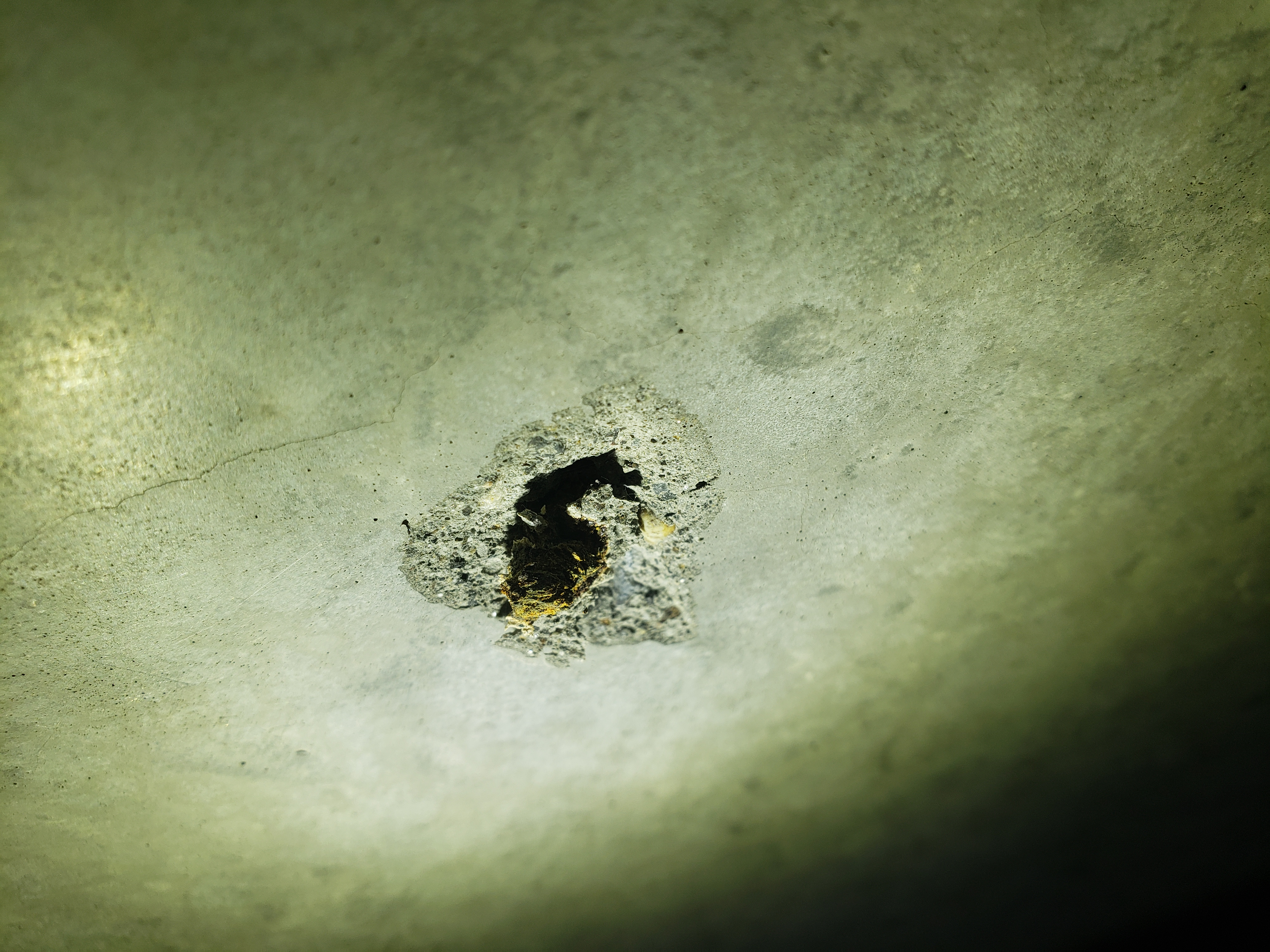
Bubba and I inspected some recently observed damage to the concrete beam tube enclosure near mid-X along X1 (not sure how long it has been there). A ~12x12" section of concrete shows signs of damage near top of enclosure. There are no burn marks to indicate a lighting strike. We inspected from inside and found some damage at same location from inside. No noticeable damage or debris on vacuum beamtube. Because this spot is almost exactly in between access doors, we took the opportunity to inspect ~ 250 ft worth of enclosure and tube while inside and found many sites with discolored growths which could be spalling. Pictures attached.
The section damaged is #25 from MX, or about 250 ft from MX along X1.
Note that LHO incurred significant snow fall this past winter.
LLO lighting strike notes: https://alog.ligo-la.caltech.edu/aLOG/index.php?callRep=33771
Thanks to TJ we figured out that the violin mode MEDM screen for ITMY (Bank2) was actually showing the colour bars for Bank 1 (although the monitor window on the right was showing the right numbers). I have fixed this issue and now the colour bars for ITMY Bank 2 is showing the correct values.
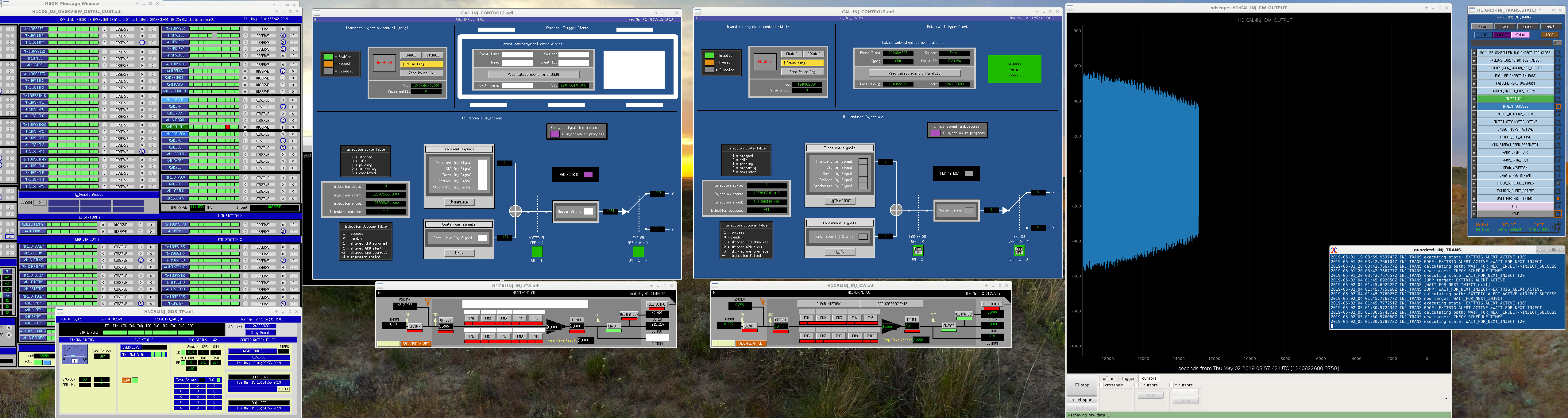
Wanted to post some info on the Injection situation.
5:23utc: Verbal Alarm says, "CW injections have stopped"
This put a red Excitation light on H1CALINJ on the CDS Overview. (Nothing is red on H1CALINJ when you look at its medm window.)
On the CAL_INJ_CONTROL2.adl medm (via sitemap/CAL/HWINJ CTRL), there's nothing RED or alarming for CW. When opening the CW button you get its filter bank, and on this only the OUTPUT is ON and all three OUTPUT channels are zero. A Time Machine of this CW filter bank from 24hrs ago shows same state for OUTPUT only being on, but you can see that the OUTMON does have a signal....this signal (and also the Calibration Injection Master Output signal) also go to zero at 5:23utc. Since there is nothing obvious I can do via the filter bank, I'm assuming this is an issue off-site and so I will leave this for others to address.
Attached is a screenshot of relevant screens to this:
A check at LLO shows CW injections still going on (attached). Unlike the Burst/CBC injections the CW injection use local resources. Now perhaps they have run out of pre-generated data. Yes we need to update our screen to use FEC 42 instead of FEC 117 for injection monitoring.
I restarted psinject (CW) at May 02 2019 15:01:58 UTC. H1 was out-of-lock at the time.
To clarify, CW injections are computed on the fly, in 20-second buffers. There are no off-site file transfers or long-term storage of strain data involved. I believe Dave will be implementing an automatic restart of crashed injections, as exists at LLO.
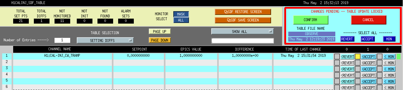
Dave and I changed ours to CAL INJ TRAMP to 1sec.
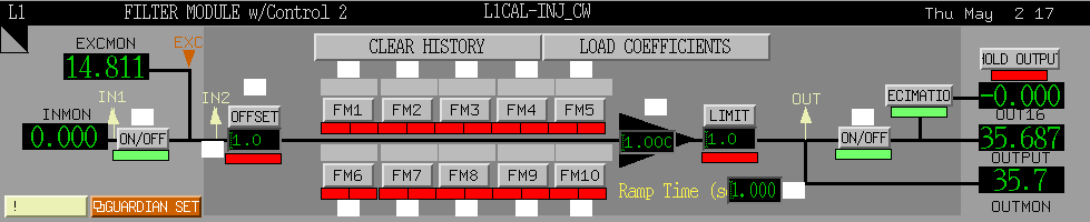
LHO should add ramping to the CW excitation. At LLO, we are using 1 second Ramp Time for L1CAL-INJ_CW (first attachment). However LHO, has a 0-second Ramp Time for H1CAL-INJ_CW (second attachment). This is why the CW injection cut off so abruptly. Both sites have a 2-second Ramp Time on the TRANSIENT. This likely got missed in the upgrade to dedicated CALINJ model.
LLO informed us that they would be out of observing for ~20 min while they damped violin modes. Virgo was also down, so we got the okay to make a small change.
1639 Out of Observing
1645 Observing
I took this opportunity to change the MICH and SRCL feedforward, with some new fits to the data I took on Friday after we'd thermalized with the SR3 heater at 4W (alog 48792).
Unfortunately, I don't think it's actually better. In the attached figure, blue is a reference from earlier in this lock, and red is after I'd switched both MICH and SRCL feedforward filters to the new fits. The MICH coherence went down, but that could be just because the SRCL made things a bit worse? We lost about 3 Mpc with the new feedforward.
This afternoon, while working on some ASC things, I reverted the SRCL FF to the old nominal Feb28 filter. I don't see a change in the DARM spectrum, but the coherence between DARM and SRCL has decreased. MICH is still using the new fits.
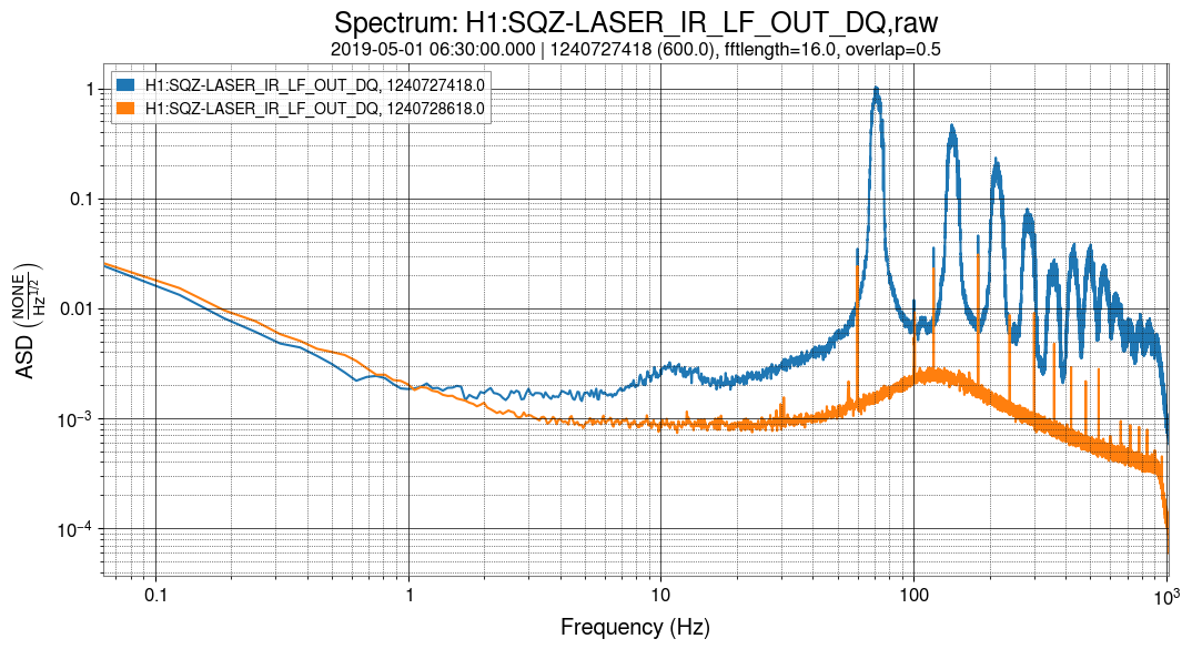
Andy, with input from Beverly, Laura, and Josh The strong wandering lines in h(t) caused by the squeezer are becoming more frequent and more severe. This seems like it could be quite a problem for the searches, so I'm putting some information here to hopefully push this to be diagnosed and resolved. The wandering line was noticed a week ago (alog 48772). It comes and goes, both in h(t) and in the squeezer channels. In the squeezer, it's an equally spaced comb of lines, with the first wandering from about 80 to 140 Hz. The line comes and goes quite suddenly. The first attachment shows what it looks like in one of the squeezer channels. This seems similar to the 200 Hz wandering line from the LLO squeezer. The solution (LLO alog 43837 was a highpass before the TTFSS. The attached PDF has spectra of several channels during the noise compared to a reference time. Nothing is visible on the fiber transmitted PD, but it is on the fiber PD, the IR laser LF, and a bunch of mixer channels. Also of note is that the CLF RF6 and REFL RF80 RFMONs both get much noisier when the lines appear. There's a very small bit of extra noise also seen on FIBR_SERVO_DEMOD_RFMON. I would speculate that this looks like a loop that's not quite stable, but everything is so coupled it's hard to tell where. Is it possible that the harmonics are generated by the noisy line going through the SHG and getting mixed with itself repeatedly?
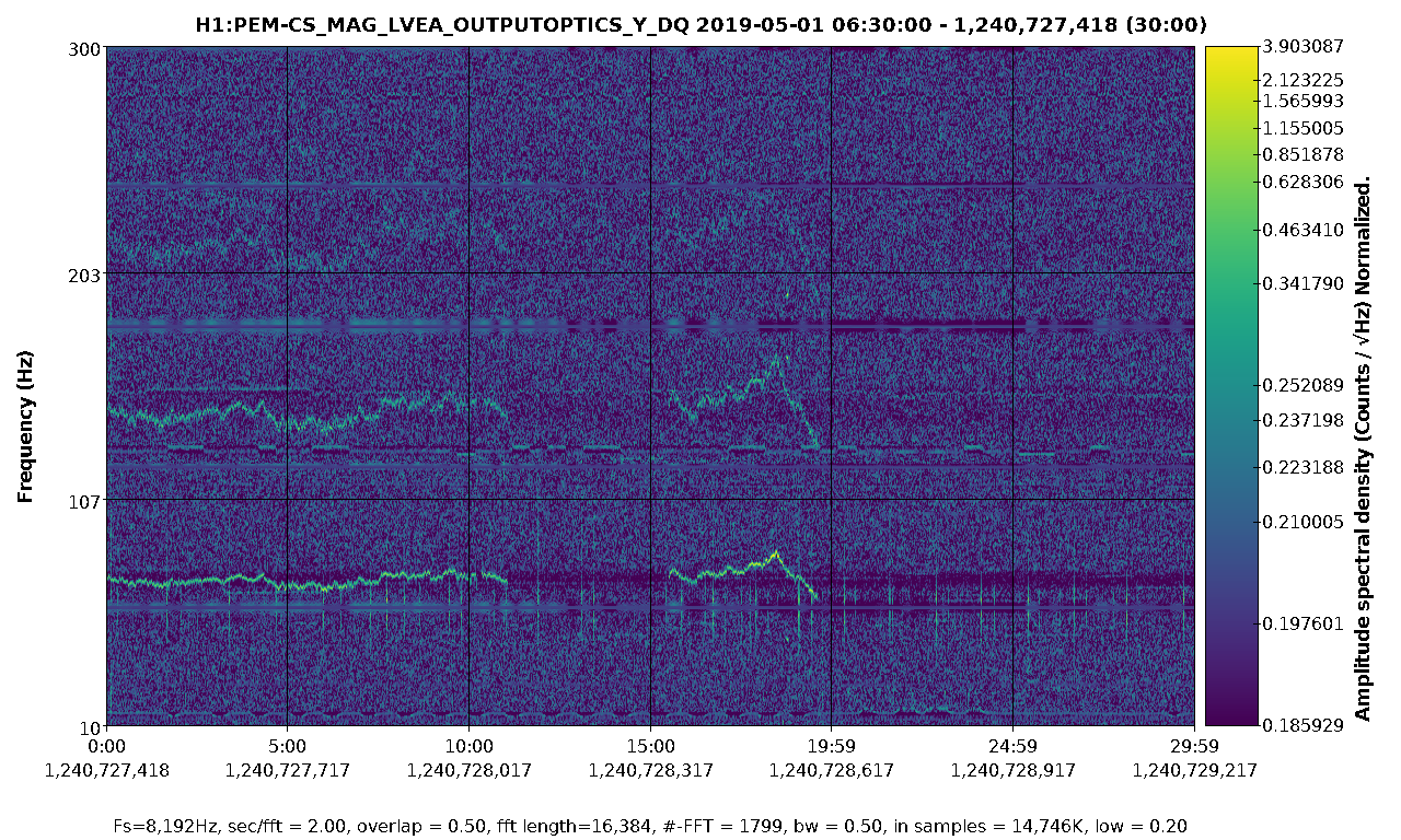
A couple of other things about this line. 1) When the line acts up, It is clearly visible in the OUTPUTOPTICS magnetometer channel which is the closest to ISCT6 2) Yesterday, the line came back as soon as got to NLN after maintenance. With Jenne's help, we closed the SQZ beam diverter - to use it as an opportunity to confirm that the squeezer was causing it. Closing it causes the line to go away in DARM, although the line is still visible in the magnetometer channel and some of the squeezer channels. The line came back when we turned it back on a minute later. Relevant spectrograms in slides 10 - 13 of the attached pdf
The high pass filter in TTFSS was added at LHO, alog 47296.
The real solution at LLO was to disable the laser noise eater on the SQZ laser. The high-pass allowed us to make that switch without other consequences.
The lines aren't the only excess noise. LASER_IR_LF has a jump in the broadband noise floor when the lines appear. I've attached a spectrogram and a spectrum. The magnetometer sees the main line and its first two harmonics. They disappear instantly whenever the lines in the squeezer do - see third attachment. It seems like this is more likely to be pickup from a problem in the squeezer, because having all of the line harmonics be EM noise seems unlikely, and there would also likely need to be broadband noise. Was there any change to the outputoptics magnetometer during maintenance yesterday? The coupling of the squeezer lines into the magnetometer is much stronger starting from the first lock after maintenance.
No, I don't think there was any change either with the squeezer or the magnetometer.
The noise eater could be toggled off and on again, using the switch on the controller mounted on top of ISCT6. It looks just like the noise eater switches on the PSL and ALS laser controllers. (Toggling it might not fix the problem, it might need to be off but it’s probably worth trying to toggle it first.)
Jenne and I went in to the LVEA and discovered the noise eater control on ISCT6 was hooked up to a remote system. Jenne toggled it off from the control room, and turned it back on ~ 30 seconds later at 16:14:55 UTC. Lets see if it works!
The noise came back, and doing an on/off test a few times indicated clearly that turning the SQZ laser noise eater off made these lines go away, so the noise eater is now off.
Whistle glitches are being seen with an increasing frequency of occurrence starting from April 22.
The stretches of time when they were seen over the last week are as follows:
* April 22 (Monday): between 09:00-11:00 UTC; this coincided with an Earthquake.
* April 24 (Wednesday): between 01:45-02:30 UTC
* April 26 (Friday): between 13:00-16:30 UTC; this coincided with a period of high winds.
Today (April 30), they can be seen throughout the stretch of Lock between 02:00-15:00 UTC.
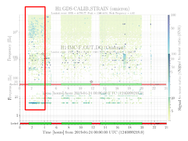
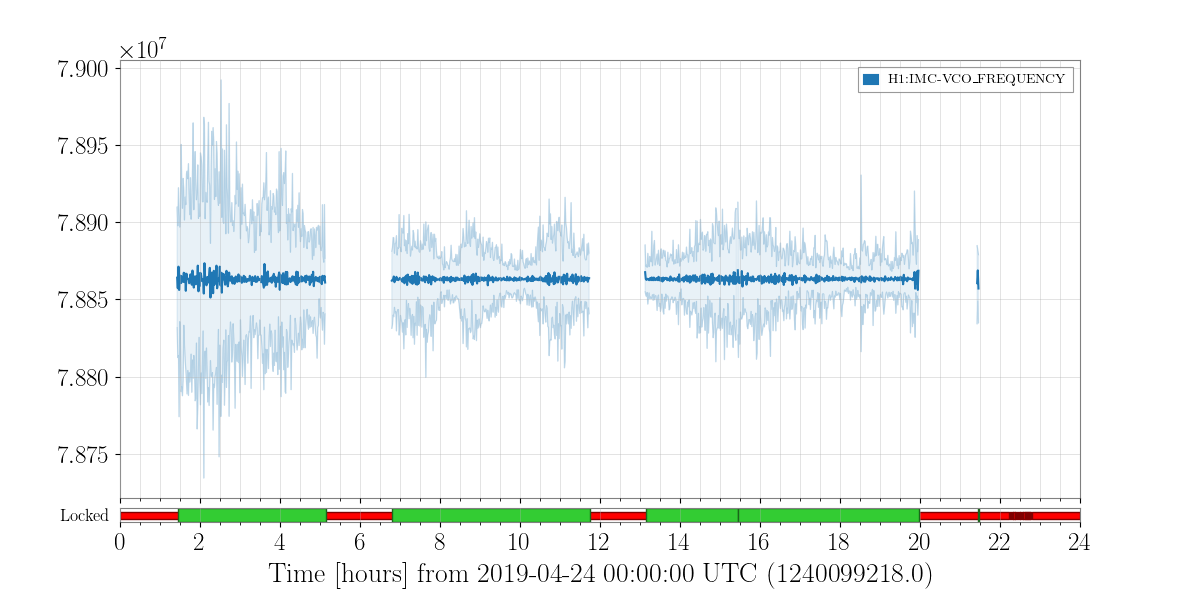
The whistles are accompanied by an increase in variance of the VCO frequency and a corresponding low-frequency (4-5 Hz.) glitching in the IMC-F motion. (plots attached from Wed. April 24).
While high winds and an Earthquake might have been the cause on a couple of instances listed above, whistles have also been seen when the wind and ground motion has not been high. It is not known what causes the increased VCO motion at other times.
I have noticed that the variance between ASC DHARD increases when that of VCO frequency increases, for example, on the following days,
* April 22 (Monday)
* April 24 (Wednesday)
* April 26 (Friday)
* April 29 (Monday).
Please let me know if someone has known this correlation.