TITLE: 04/10 Day Shift: 15:00-23:00 UTC (08:00-16:00 PST), all times posted in UTC
STATE of H1: Corrective Maintenance
OUTGOING OPERATOR: Jim
CURRENT ENVIRONMENT:
Wind: 19mph Gusts, 16mph 5min avg
Primary useism: 0.07 μm/s
Secondary useism: 0.22 μm/s
QUICK SUMMARY: H1 lost lock at 15:01 UTC, possibly related to Safety System issues that Richard is currently working on.
TITLE: 04/10 Owl Shift: 07:00-15:00 UTC (00:00-08:00 PST), all times posted in UTC
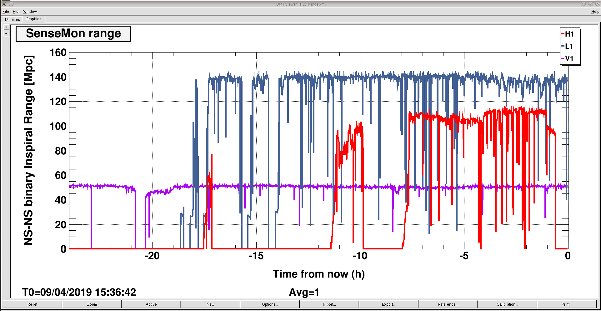
STATE of H1: Observing at 93Mpc
INCOMING OPERATOR: Travis
SHIFT SUMMARY:
LOG:
11:20 Starting suite of cal measurements
13:30 Cal measurements done, back to observing
14:30 Safety system has some sort of failure, killing all of the lasers except for the PSL, Richard is on the floor trying to fix it
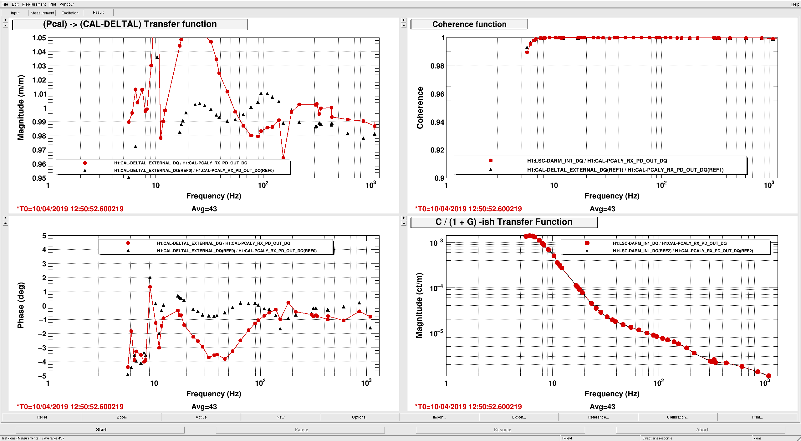
I was left with a small novel describing some calibration measurements that needed to be run. I tried to follow Jeff's instructions, but I don't think everything ran as it was intended. Two measurements described as "Sensor measurements", one doesn't look like the reference and the other doesn't look like it actually ran the excitation properly.
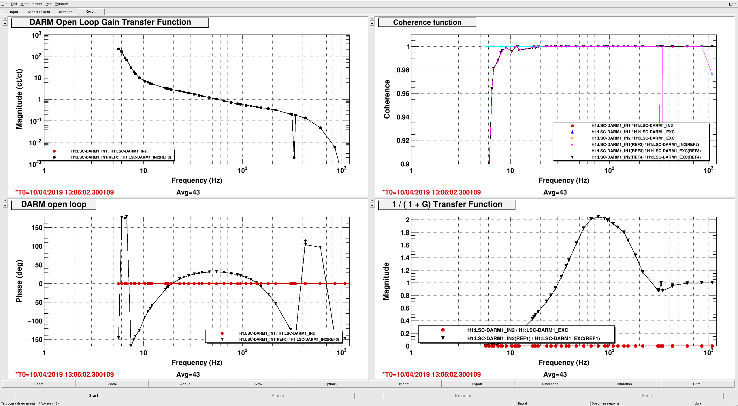
2019-04-10_H1DARM_OLGTF_5to1100Hz_30min.xml <-- this TF is just flat and doesn't look like it actually went.
2019-04-10_H1_PCAL2DARM_TF_5t1100Hz_15min.xml <-- this looked like it ran, but the measurement doesn't look like the reference.
Everything else seemed to go okay, other than the implied times in the file names didn't seem to actually reflect how long the measurements would take. Often a "25min" measurement was more like 10 minutes. I've saved all the new data as requested and left all the measurements up on the workstation that was set up for the measurements.
Thanks Jim and TJ! I'm super happy that y'all got as much as you did -- especially given last night's 50 mph winds from Winter Storm Wesley!
The actuator measurements that were successful:
/ligo/svncommon/CalSVN/aligocalibration/trunk/Runs/O3/H1/Measurements/FullIFOSensingTFs
2019-04-10_H1SUSETMX_L1_iEXC2DARM_25min.xml
2019-04-10_H1SUSETMX_L1_PCAL2DARM_8min.xml
2019-04-10_H1SUSETMX_L2_iEXC2DARM_17min.xml
2019-04-10_H1SUSETMX_L2_PCAL2DARM_8min.xml
2019-04-10_H1SUSETMX_L3_iEXC2DARM_8min.xml
2019-04-10_H1SUSETMX_L3_PCAL2DARM_8min.xml
I agree with Jim's assessment of the times on the file names, we've been messing around with the excitation amplitudes and frequency vectors and haven't updated the file names.
The sensing measurements which were only 1/2 successful:
/ligo/svncommon/CalSVN/aligocalibration/trunk/Runs/O3/H1/Measurements/FullIFOSensingTFs
2019-04-10_UTC_H1DARM_OLGTF_5to1100Hz_30min.xml <-- DTT disease -- failed to gather data because template is corrupted, shows a transfer function with magnitude and phase of identically 0.0, with 0.0 coherence. Usually just an "abort" and (re)"start" (after seeing a few data points of zero) will work.
2019-04-10_UTC_H1_PCAL2DARM_TF_5t1100Hz_15min.xml <-- This was successful, and although Jim said this "doesn't look like the reference" that's OK. We know this template's calibration is incorrect, but just haven't had time to fix it.
Model parameter set installed in to CAL-CS during these measurements:
/ligo/svncommon/CalSVN/aligocalibration/trunk/Runs/O3/H1/params
modelparams_H1_20190404.py
based on measurements from 2019-04-03 (from LHO aLOG 48220).
Changes to CAL-CS calibration:
- Change the model actuator gains from 0.95 to 1.
caput H1:CAL-CS_DARM_ANALOG_ETMX_L3_GAIN 1.0 (was 0.95)
caput H1:CAL-CS_DARM_ANALOG_ETMX_L2_GAIN 1.0 (was 0.95)
caput H1:CAL-CS_DARM_ANALOG_ETMX_L1_GAIN 1.0 (was 0.95)
- Flip the actuation strength filters "Npct" from ER14 to O3
in the same banks as above, switch from FM9 to FM4 (updates we *very* small, changes at the less-than-0.5% level, but installed just to be consistent with MCMC fits of measurements)
- Change the sensing function filters "Gain" and "D2N" from ER14 to O3
In H1:CAL-CS_DARM_ERR bank, switch FMs 9 and 10 to FMs 7 and 8 (updates were mostly to spring frequency and Q, and small, 1% level nudges to the optical gain and cavity pole frequency.)
- Change delay between actuator and sensing paths from 7 to 9
caput H1:CAL-CS_DARM_CTRL_DELAY_CYCLES 9.0 (was 7.0)
- write new reference model parameters at calibration line frequencies
cd /ligo/svncommon/CalSVN/aligocalibration/trunk/Runs/O3/H1/Scripts/CALCS_FE/
python3.5 createEPICS_for_20190404.py -w
EPICs Records installed during these measurements:
/ligo/svncommon/CalSVN/aligocalibration/trunk/Runs/O3/H1/Results/CALCS_FE
epicsrecords_model-H1_20190404_created-20190410.txt
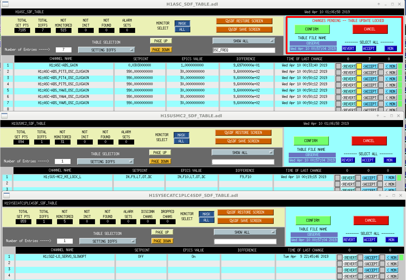
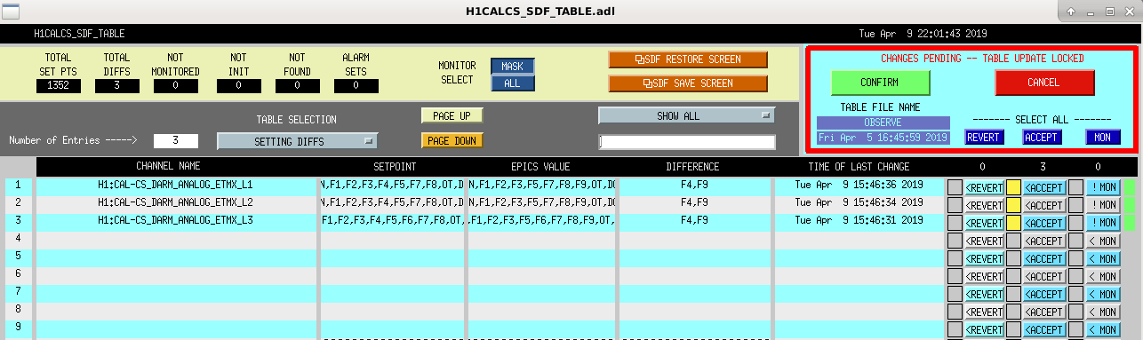
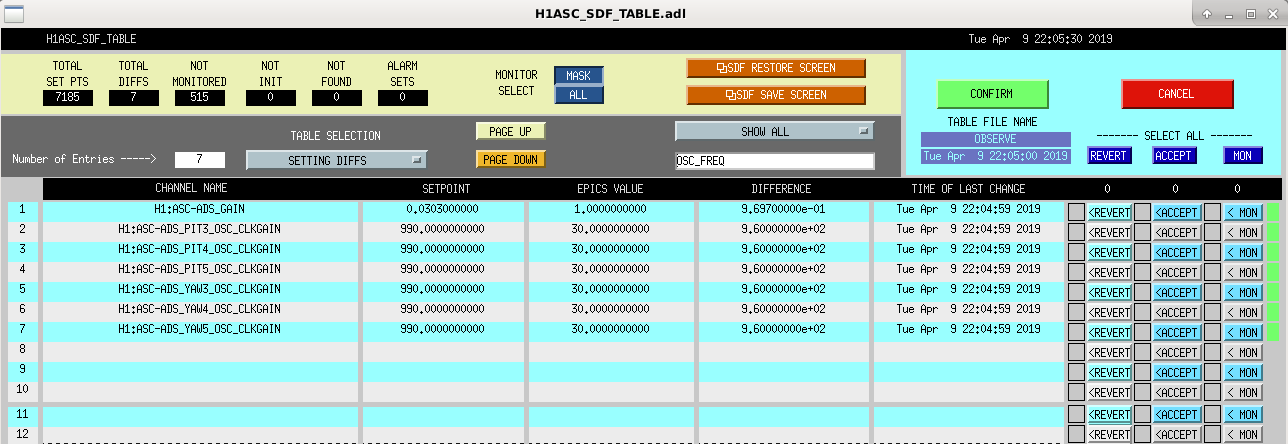
IFO just relocked, there are some SDF difffs, that I'm not sure the origin of. The ADS diffs I know come from TJ struggling with wind induced scattering, but there is an MC2 M3 LOCK L filter changer and a SQZ LO SERVO SLOWOPT. Near as I can tell, things are otherwise fine, so accepting to go to observe.
TITLE: 04/10 Eve Shift: 23:00-07:00 UTC (16:00-00:00 PST), all times posted in UTC
STATE of H1: Aligning
INCOMING OPERATOR: Jim
SHIFT SUMMARY: Winds were a problem the entire shift, but might be at a managable level now. I just finished an initial alignment and will hand off to Jim.
LOG:
The wind is causing a scatter shelf larger than the ADS lines much of the time, so it was suggested that I turn up the ADS lines. I accepted the larger lines in SDF so we could go to observing for a bit.
Other things I had to accept in SDF:
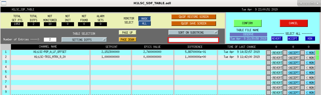
LSC - Not sure about these, didn't see anything in a alog about it.
CALCS - For the measurements that I will be taking after we thermalize, I was instructed to change these, but it seems that they were already accepted as changed at some other time. Accepted in this configuration for now.
ASC - The larger ADS lines
Lock loss 0545UTC
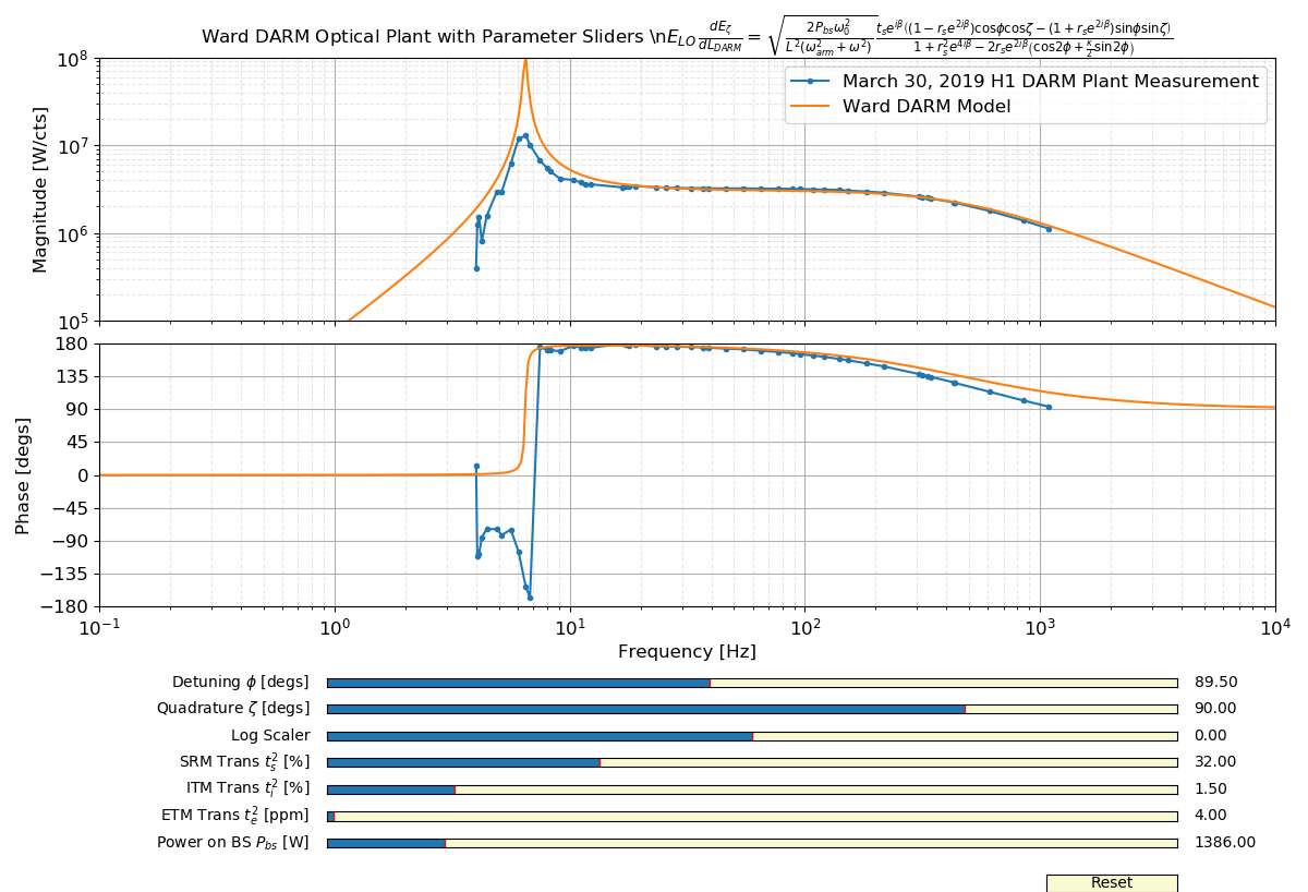
We've measured the DARM plant to have a prospring at 6 Hz and a Q of about 4. About the spring frequency, the phase goes through around -90 degrees, and not the expected +180 degrees alog 48083 This +180 degrees is not typical for causal control systems, but it is expected from SR IFOs as discussed in Section II B from BnC. Using the Ward DARM model (Eq 3.83) I was unable to achieve a satisfactory fit of the H1 DARM plant at low frequencies, so I made some sliders to see if I could get a heuristic match. I was not able to for reasonable IFO parameters. I discovered that our Q is far too low given our optic transmissions. One can lower the Q of the optical spring by increasing the SRM transmission or reducing the ITM transmission. However, changes to these parameters also change the frequency of the optical spring and the DARM pole. The pictured plot shows the best Ward model I was able to come up with to explain the current plant, featuring detuning of -0.5 degrees. DARM Plant Measurement I began questioning the measurement itself, but the procedure is pretty simple. A PCAL to DARM measurement gives C/(1 - G), where C is the DARM plant, and G is the DARM OLG. Then a DARM OLG is taken to get 1/(1 - G), and these two measurements are divided to give the DARM plant C. The PCAL calibration into meters is just two real poles at 1 Hz. This has phase of -160 degrees at 6 Hz, i.e. there is some dynamic phase rotation happening at LF due to the calibration which may not be real.
Does it change with arm power? dc offset power? Does AS45 see the same feature?
March 13 antispring DARM plant at 30 W Input Power and 0 W on SR3 heater: 47493 March 18 antispring to prospring at 30 W Input Power with 0 W to 5 W on the SR3 heater: 47604 March 20 prospring at 35 W Input Power with 5 W on SR3 heater: 47728 April 12 prospring at 35 W with 5 W to 3.5 W on SR3 heater: 48453 There have not been tests for the following: - Spot positions (for L2A2L effects) - SRCL offset - DARM offset Based on the above results, I think that higher arm power and higher SR3 heater power both push the DARM optical prospring to higher frequency. Danny Vander-Hyde tells me that the SRC gouy phase goes like around ~1 degree/watt of SR3 disk heater power, so we probably change the SRC gouy phase by ~5 degrees on March 18.
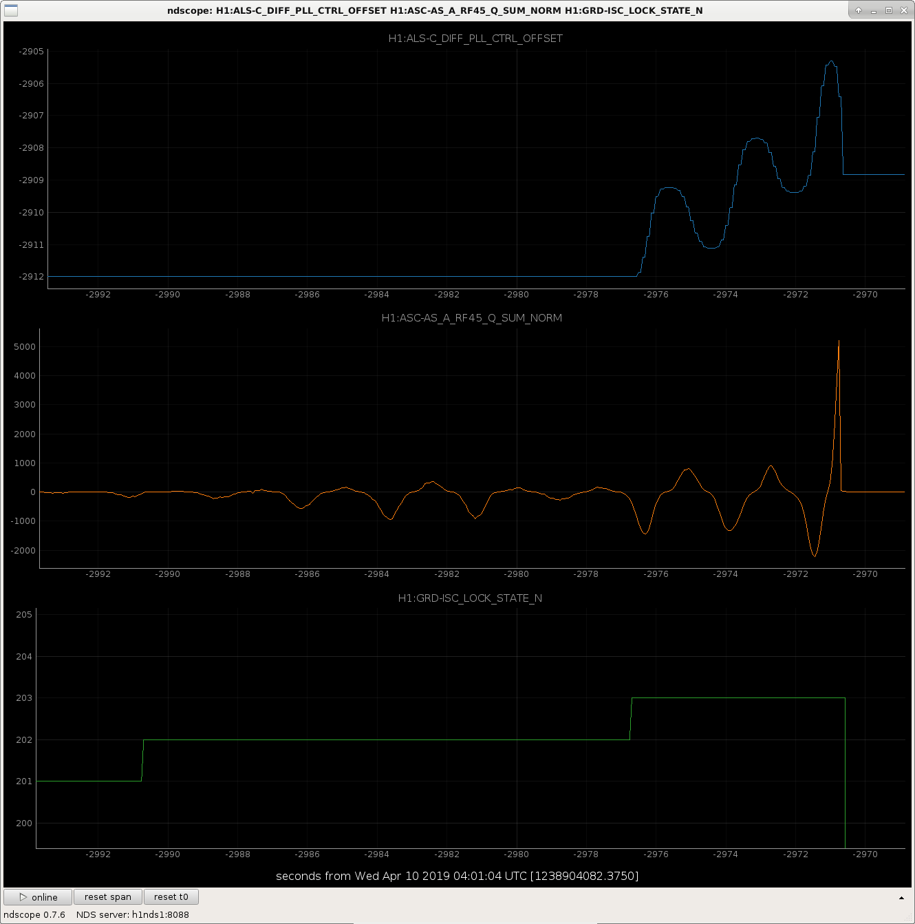
We had several locklosses early in the CARM offset reduction sequence tonight. In the CARM_150_PM state we servo the ASC_AS_A_RF45_Q_SUM_NORM to zero using the DIFF_PLL_OFFSET. In the past Sheila and I have lowered the gain on that servo (set in guardian) as it seemed to be injecting noise and causing locklosses.
I had a look at these channels and it seems like turning the servo on is not helping to stabile AS_A_RF45. Something in this process needs retuning for these windy conditions (see attached screenshot).
The gain is nominally 0.004 (ISC_LOCK guardian line 1587), I tried decreasing it, and while we did survive a little longer we still lost lock shortly afterwards. I tried increasing it, and we did make it through the state, so I am leaving it at 0.01.
Do we actually need this servo? If this state continues to cause locking issues perhaps future operators could just comment out line 1598 of ISC_LOCK and see if just not turning it on helps.
Georgia, Danny
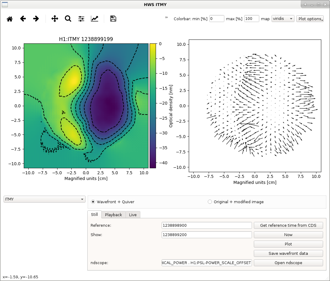
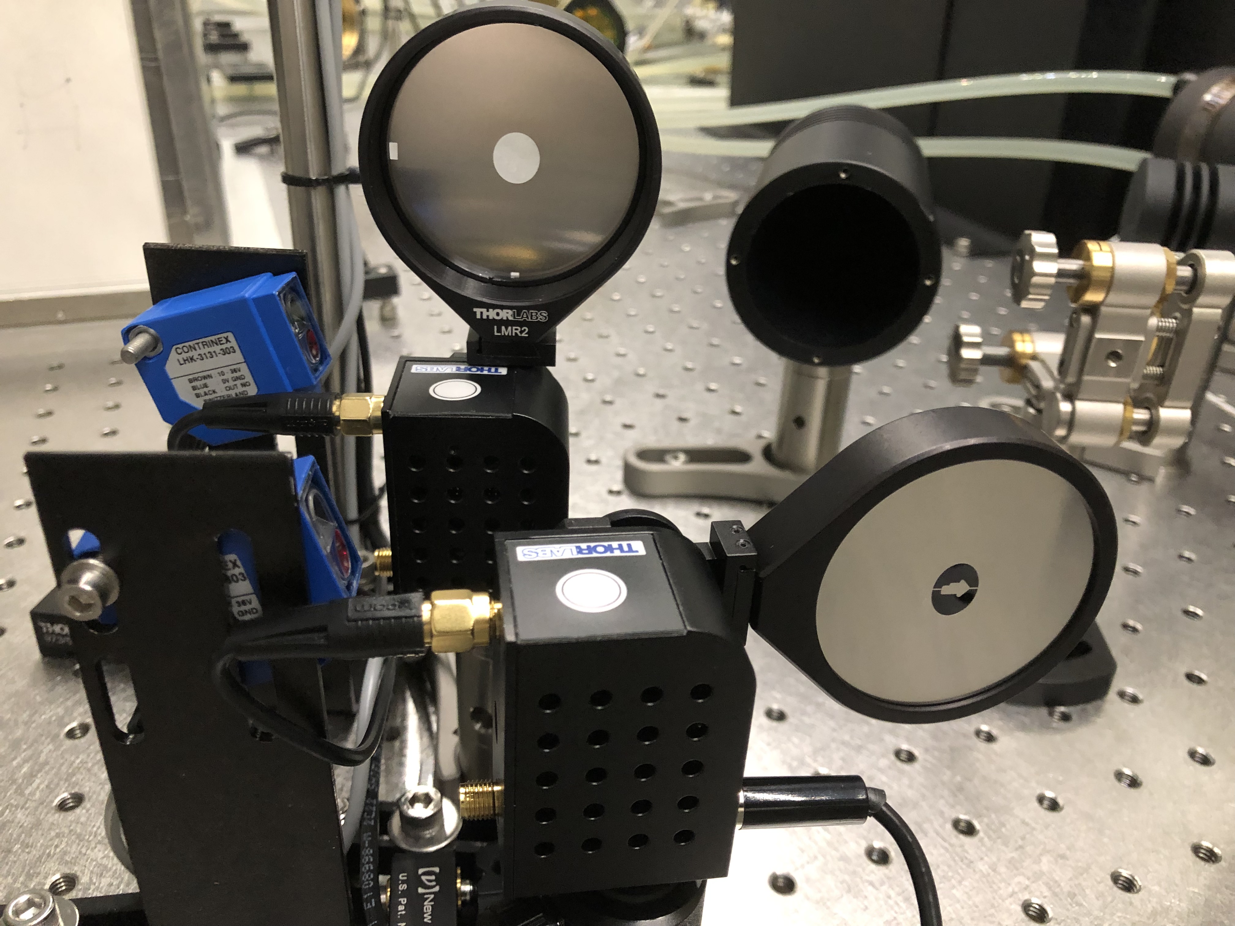
With different ITM spot positions we have changed how the point absorbers contribute to the overall optical path distortion. This makes the first CO2Y mask design (Mask 1) less helpful, Aidan designed a second iteration of the CO2Y mask (Mask 2) in order to better accommodate for the new optical path distortion. We installed this new mask today into the annular mask beam flipper.
We believe the mask should be installed in the flipper as indicated in the first figure.
Some notes on the installation of Mask 2:
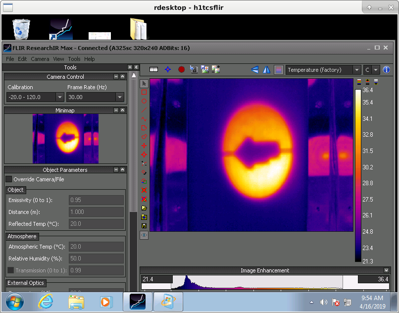
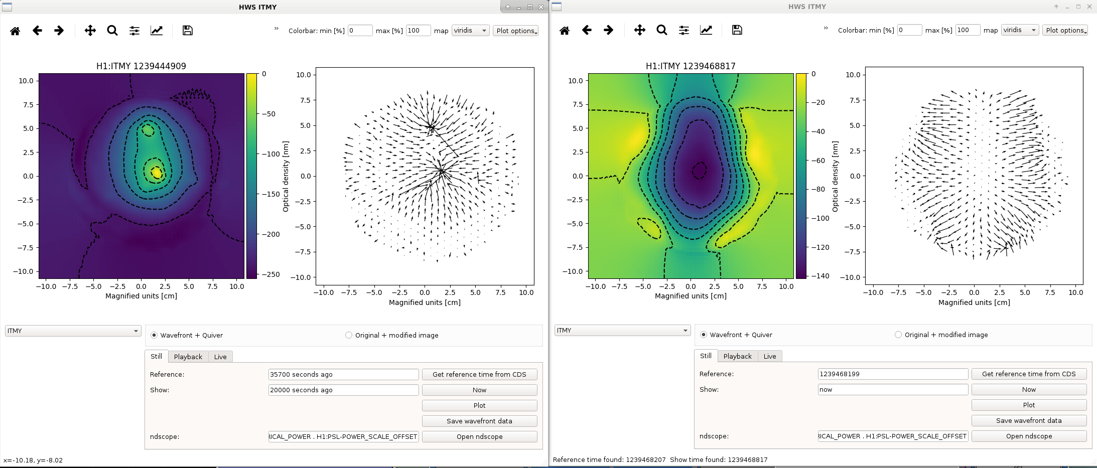
Made some fine adjustments to the installed mask (Mask 2). A FLIR image is attached. Also attached are Hartmann images comparing the centering of the optical path distortion from the point absorbers (left) and the optical path distortion of CO2Y with the mask in its current alignment. It is important to note that the optical path distortion shown in the HWS image to the right is caused by a short duration 2.4W CO2 step up and not fully representative of the distortion you expect to see at thermal equilibrium.
Jenne, Craig We are wondering why our range did not go up when we increased the power from 30 to 35 watts. Assuming responsivity = e λ / (h c) = 0.858 A/W, I used the 330 Hz PCALY line to find the optical gain today (April 9, 2019) and before the 30 to 35 W power input increase (which happened March 18, 2019):35 W DARM Optical Gain = 3.87 mW/pm 30 W DARM Optical Gain = 3.71 mW/pm Optical Gain Increase = 4.3 %I checked the actual input power measured according to IM4 as well:35 W Input Power = 30.8 W incident on PRM 30 W Input Power = 26.5 W incident on PRM Power Input Increase = 16.0 %We servo the DARM offset to always keep 20 mA on our OMC DCPDs. DARM offset decreases like the sqrt(Antisymmetric Power) increases: Pas ~ DARM offset2:35 W DARM offset = 10.1 pm 30 W DARM offset = 11.0 pm DARM offset Decrease = 8.1 %Checked the power recycling gain:35 W PRG = 45.0 30 W PRG = 46.3 PRG Decrease = 2.8 %According to Kiwamu Eq 11, DARM optical gain goes likedPas/dLDARM = 8 * k2 * Input Power * DARM offset * PRG * Signal Recycling Gain * Arm Reflectivity Derivativewherek is the wave number 2π/λ PRG = (tPRM/(1 - rARM * rPRM))2 SRG = (tSRM/(1 + rARM * rSRM))2 Arm Reflectivity Derivative = drArm/dφ = ( tITM2 rETM / (1 - rITM rETM)2 )2DARM Optical Gain goes linearly with PRG, DARM offset, and Input Power. From the changes above, we find our DARM optical gain should have increased by around 4 %. This is pretty much what we see. So why didn't the range increase? My guess is, it did, but on the night of the power increase we didn't see any immediate improvements due to bad spot positions and TCS for higher power. Later with the calibration changes and other commissioning tasks happening at the same time we got confused about what our range really was. In any case, we did win with the power increase (after ~month of ASC/TCS commissioning), and we have no reason to believe that going up further would not help us.
Craig and I have also been looking at what we expect our optical gain to be given what we know about our interferometer.
One thing to recall (thank you Sheila for finding this factor of 2!) is that we usually call DARM (Lx-Ly), but Kiwamu's equations are based on a DARM definition of (Lx-Ly)/2. In our usual notation, our DARM offset is roughly 10pm, but in the Kiwamu notation it is 5pm. This factor divides out when looking at an optical gain ratio as Craig does, but is important for trying to calculate the expected optical gain.
In the 'more typical' DARM notation that we use, Kiwamu's derived equation becomes:
dPas/dLDARM = 8/4 * k2 * Input Power * DARM offset * PRG * Signal Recycling Gain * Arm Reflectivity Derivative^2 * J0(Gamma1)^2 * J0(Gamma2)^2
Also of note is that this equation doesn't include any output losses, such as transmission through the OFI, mode matching to the OMC, and perhaps unknown others, which I will include to give a more realistic estimate of our expected optical gain.
If we say that the power circulating in the arm cavities is given by P_arm = P_in/2 * J0(Gamma1)^2 * J0(Gamma2)^2 * PRG * arm reflectivity derivative, we can solve for the arm reflectivity derivative (difficult to directly measure) in terms of measured power circulating in the arm (easier to directly measure). This lets us compare our expected optical gain and that measured in Craig's alog.
Rewrite: dP_as / dL_DARM = 2 * k^2 * P_in * DarmOffset * PRG * SRG * J0(Gamma1)^2 * J0(Gamma2)^2 * OutputLosses * (2 * P_arm / P_in * 1/PRG * 1/J0(Gamma1)^2 * 1/J0(Gamma2)^2 )^2
k = 2*pi/1064e-9 1/m
P_in = 31.3 W (injected to PRM measured by IM4 trans, when 35W injected to vacuum)
P_arm = 184 kW (average of our 2 arms, alog 47722)
DarmOffset = 10.1 pm
Gamma1 = 0.160 (alog 47113 for 9 MHz)
Gamma2 = 0.182 (alog 47113 for 45 MHz)
T_etm = 3.85 ppm (power transmission, average of 2 ETMs from as-built page)
T_itm = 1.46 % (power transmission, average of 2 ITMs from as-built page)
T_prm = 3 % (from as-built page)
T_srm = 32.34% (from as-built page)
Loss_arms = 75 ppm (we don't have a good measurement of this, so using a value that gives a PRG of 44.5)
Calculated PRG = 44.5
Calculated SRG = 0.09 (Assumes R = 1-T, L_SRC = 0)
Power reflectivities of the arms are R = 1 - T - Loss/2, so that I am splitting the total loss in the arm between the ITMs and ETMs. Somewhat arbitrary, doesn't really change things if I put all the loss on the ETMs.
The OutputLosses is somewhat hard to say what they should be. If I say that the SRG is only 70% of the ideal, and we have an additional 20% in losses from the SRM to the OMC and in OMC mode matching, then I get an optical gain value of 3.88 mW / pm, which is very close to Craig's measurement of 3.87 mW/pm. But, that seems like a lot of losses at our output. If instead I say that our losses are perhaps more realistic, with SRG 80% of ideal, and 10% extra losses from SRM to OMC and in OMC mode matching, then I get an optical gain value of 4.99 mW / pm, which would imply that we're missing about 30% of our potential optical gain.
Things also start to get a bit tricky with such a big change in optical gain, since we servo our DARM offset such that the OMC DCPDs see 20 mA of photocurrent.
Unfortunately, not having a very good idea of a number of output losses means that I don't really have a good conclusion here on how much optical gain we're missing out on due to (potentially) non-optimal spot positions in the arm cavities, which means it's hard to say what we might gain in range with (potentially) better spot positions.
Shifter: Sumeet Kulkarni
Fellow/Mentor: Greg Vaughn-Ogin
Complete details can be found at https://wiki.ligo.org/DetChar/DataQuality/DQShiftLHO20190401
Nutsinee Daniel
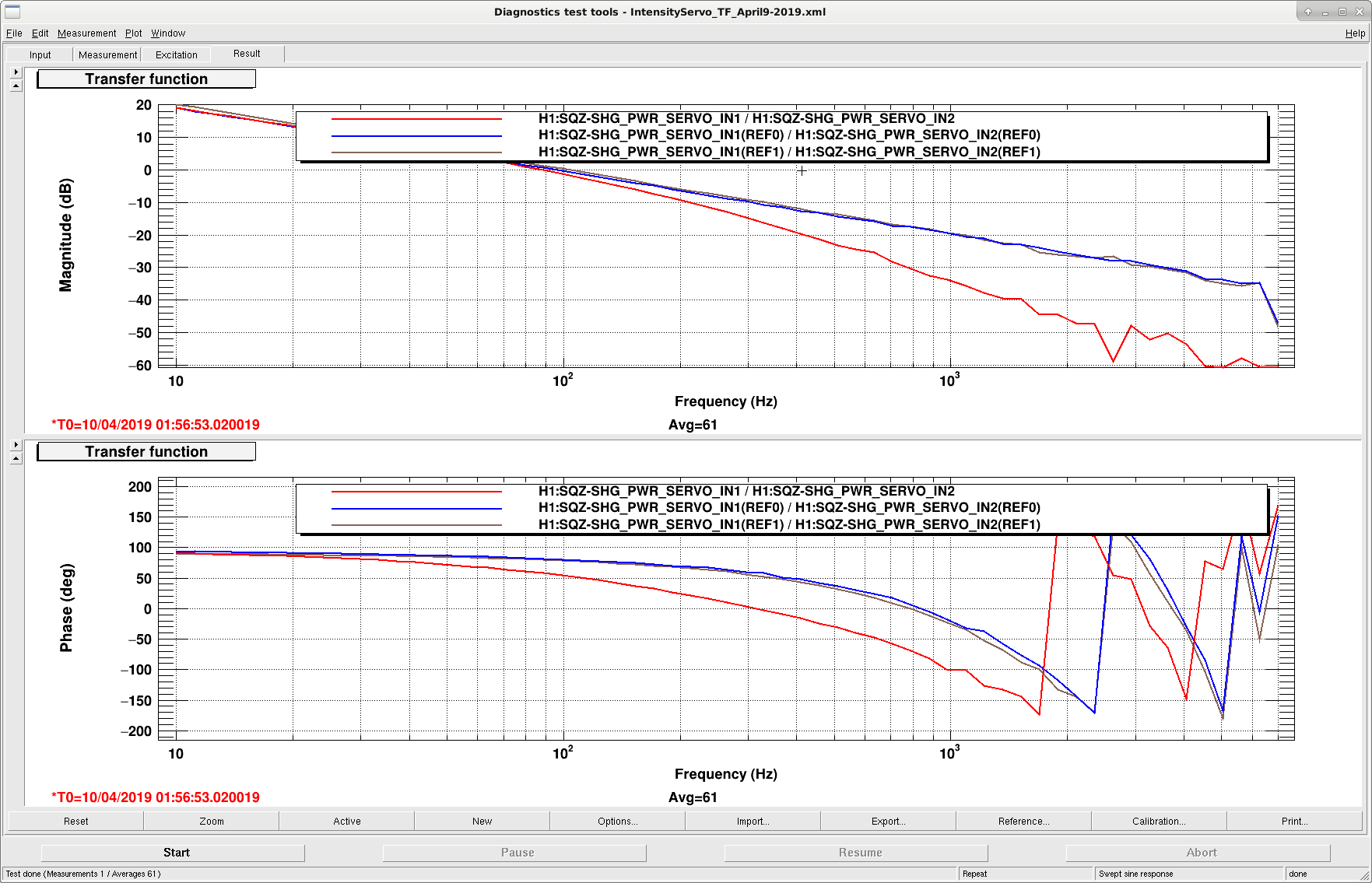
Plot 1 shows the open loop gain of the servo. Blue and brown represent the original TF using the OPO TRANS and REFL as error signals, respectively. Ugf is 100 Hz. The red curve is after we added a 200 Hz low pass filter to reduce high frequency noise.
Plot 2 shows the noise of the OPO TRANS and REFL photodetectors: the green curve shows the noise with the servo off, the red curve is with REFL as the error signal, the brown curve with TRANS as the error signal, and black represents the dark noise.
Plot 3: Coherence for the above spectra. There is a lot of uncorrelated noise below ~10 Hz.
The default error signal is now the transmitted power of the OPO. Nominal power in transmission is 325 nW, and 0.945 mW in reflection.
Daniel, Nutsinee
Current|Temperature from before: 1.955A | 33.72C
Current|Temperature now: 1.935A | 33.73C
This was a quick fix just to get away from the multimode given the amount of time we had. Hopefully it's good until next Tuesday. A proper mapping of good current/temperature region still needs to be done.
Due to less current we are also putting less red into the SHG. Daniel adjusted the SHG temperature to optimize the green output (was 35.8C, now 36.9C). 35.8C was set for 100mW of red input to the SHG. He also tweaked the red alignment into SHG, upped the power by 2%. Alignment tweaking hasn't been done at least since the last time the laser current was adjusted. Changing laser current/temperature might have changed the alignment into the SHG.
Craig, Danny, Georgia
This week (nominally tomorrow) we plan to try taking some small steps down in power with the SR3 heater. We will run several injections before taking each step, and to leave the interferometer in Observing for an hour at a time between steps, while the system reaches thermal equilibrium.
* Engage SR3 cage servo
* Let IFO thermalise
* Injection: DARM plant (DARM and PCAL excitations)
* Injection: Frequency noise (Band-limited Craig injections)
* Injection: Intensity noise (Noise budget style broad band injections)
* Injection: 9 MHz RIN (Broad band injection)
* (Maybe) turn off ADS (caused problems in the past when SR3 heater serring changed)
* Reconcile SDF, return to observing for 1 hour
* Check for offsets in SRC ASC
* Rerun all injections listed above
* If ADS is off, maybe let it come back on and converge
We will repeat this for ~3 steps of the SR3 heater
Marc Nutsinee Daniel
All common mode boards in the squeezer rack (CLF S/N S1700344; OPO S/N S1700345; SHG S/N S1700346; LO S/N S1700348) as well as the 2 spares (S/N S1700347 & S/N S1700349) were modified according to E1900103 (high pass filtering of DAQ channels to avoid slew rate limitations in the AA chassis).
Installed the AM modulated AOM driver chassis D1900045 (S/N S1900202) and removed the temporary ifr RF synthesizer and Mini-Circuits RF amplifier.
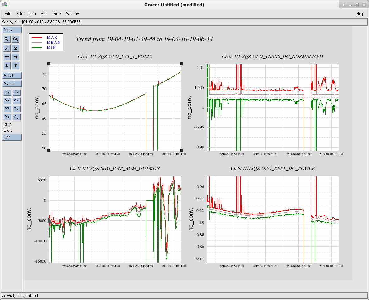
Updated the model to add a dedicated integrator at the output of the green pump power stabilization. This prevents the filter output from increasing to very large numbers, when the actuator is out of range. The servo can now be turned on and off with a trigger from the OPO transmitted power.
When we tried to relock the squeezer, we had to fix several problems with broken equipment!? Cause unknown.
We replaced the PZT driver with the spare (S/N S1700172) which fixed the offset problem for the SHG.
We checked the CLF drive at the output of the AI board and found the same problem: both legs of the differential signal are pegged at -13V. This eliminates the cable as a problem.
Attached transfer functions of LO, OPO, and SHG board. CLF excitation didn't work.