Displaying reports 41921-41940 of 88748.Go to page Start 2093 2094 2095 2096 2097 2098 2099 2100 2101 End
Reports until 15:58, Friday 05 April 2019
H1 CDS (GRD)
david.barker@LIGO.ORG - posted 15:58, Friday 05 April 2019 (48270)
stranded guardian git lock file caused ISC_LOCK problems

Sheila, Jenne, Dave:

After the ISC_LOCK guardian node was reloaded, it reported a "HEAD.lock file exists" error. The file in question was /ligo/cds/lho/h1/guardian/archive/ISC_LOCK/.git/logs/HEAD.lock which was last modified 12:11 Tue 02apr2018, this is the time we rebooted h1guardian1.

This file had zero permissions,

---------- 1 1010 controls       0 Apr  2 12:11 HEAD.lock

I deleted it as root on the NFS server. I also proactively scanned all the .git directories to see if any other lock files a lurking, there are none.

H1 AOS
edmond.merilh@LIGO.ORG - posted 15:34, Friday 05 April 2019 - last comment - 15:35, Friday 05 April 2019(48268)
H1 Back to Observing

DMT doesn't seem to be working.

Comments related to this report
edmond.merilh@LIGO.ORG - 15:35, Friday 05 April 2019 (48269)

it's back

H1 General
edmond.merilh@LIGO.ORG - posted 15:14, Friday 05 April 2019 (48267)
Intent Bit Knocked out by Squeezer Guardian

Ed, Sheila

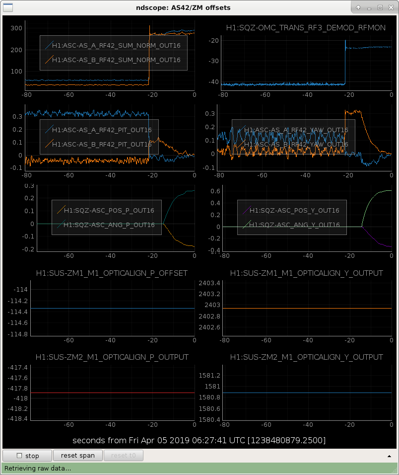
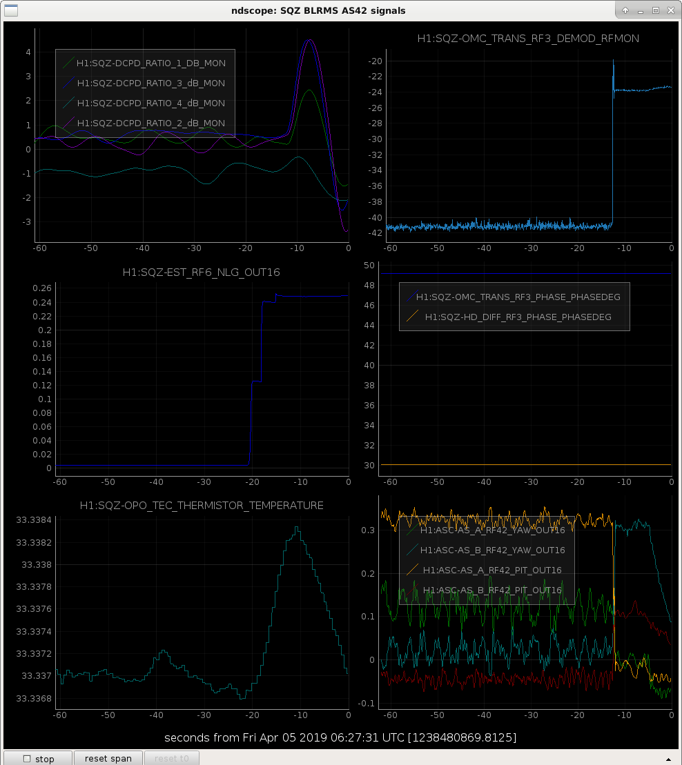
The intent bit was kicked into COMMISSIONING by the squeezer spontaneously unlocking. I followed the instructions set by TJ via his email :     SQZ_MANAGER edit instructions for unlocked squeezer kicking the intent bit to COMMISSIONING The editing, committing, reloading, and selecting the new nominal SQZ_MANAGER state went well. Re-selecting NOMINAL_LOW_NOISE in ISC-LOCK to accept the new changes didn't go so well. Sheila is currently working to restore the peace.

H1 SUS
rahul.kumar@LIGO.ORG - posted 13:47, Friday 05 April 2019 (48266)
update on Guardian state for Violin mode damping

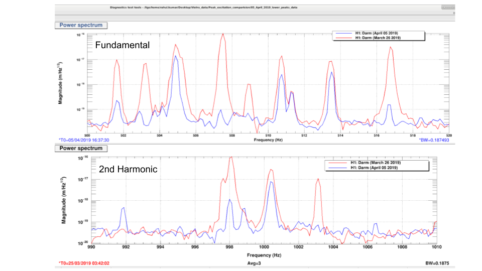
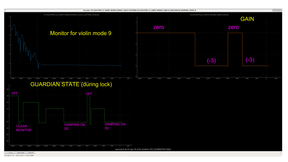
The violin mode damping code seems to be working well after some changes were made to it, as discussed in the LHO alog  (48239). The figure attached shows the ndscope of ETMX mode 9 (sample case) taken during IFO locking. The three plots are of Guardian states, monitor level (for etmx 9) and the GAIN. GUARDIAN is actively applying the GAIN whenever it's on DAMPING_ON_DC and shutting it off elsewhere.  The second plots shows the power spectrum of the 1st (fundamental) and 2nd harmonic for the violin modes. Red line represents the data taken on 26 March 2019 and the blue line is for the April 5 2019. The plot clearly shows that guardian is applying the GAIN and is successfully damping many of the modes.

Fundamental harmonics -  Earlier 8 modes where excited to the level around 10^-17 m/sqrtHz and above. Now, 5 out 7 modes have been damped to a level of 10^-18 or below.

2nd Harmonics - 3 peaks were seen around 10^-17 m/sqrtHz and above, out of which 2 have been damped down to 10^-18 m/sqrtHz and below.


Images attached to this report
H1 General (SEI, VE)
stephen.appert@LIGO.ORG - posted 11:01, Friday 05 April 2019 (48263)
Wind Fence and A+ FC sketches posted to DCC at A+, General Arrangement Drawing (H1)

A+, General Arrangement Drawing (H1) at D1900069 (public link)

EddieS posted the above document with views of A+ 300m FC, Wind Fences, and STEM center in the context of LHO site layout and Camera views from Rattlesnake Mountain. Folks at LHO might like to see these sketches and know that they exist! Good work by Eddie.


H1 General
edmond.merilh@LIGO.ORG - posted 10:41, Friday 05 April 2019 (48262)
Lockloss - EQ S Sandwich Island area

17:24 Lockloss

EARTH_QUAKE SEI_CONF was engaged minutes before without breaking the lock. ADS line were adjusted by commissioners, simultaneously, which will need to probably be integrated into the ISI transitioning processes. the Transition didn't blow the lock but the EQ motion coupled with 90%ile uSei was to much for "her". Observation mods was set to Environment/Earthquake and will remain there until re-lock is acquired and intention bit is set, barring any opportunistic commissioning that might take place while Livingston is down.

H1 CDS
david.barker@LIGO.ORG - posted 08:32, Friday 05 April 2019 - last comment - 11:51, Sunday 07 April 2019(48260)
h1calcs crontab to diag_reset not working

My python script to diag_reset h1calcs when it occasionally runs long is not working as a cronjob. For now I'm running it in a tmux session on h1fescript0 (looping every minute) until I can get the cronjob functional.

Comments related to this report
david.barker@LIGO.ORG - 11:01, Friday 05 April 2019 (48264)

Running again as a cronjob once I got the environment sorted out.

david.barker@LIGO.ORG - 11:51, Sunday 07 April 2019 (48300)

attached image of h1calcs cpu_meter_max shows an automatic reset event at 17:15 UTC (10:15 PDT) Saturday morning. Within the same minute the cpu went to 63uS (the TIM bit was set on STATE_WORD) and then DIAG_MAIN was reset.

Images attached to this comment
H1 General
edmond.merilh@LIGO.ORG - posted 08:04, Friday 05 April 2019 (48258)
Shift Transition - Day

TITLE: 04/05 Day Shift: 15:00-23:00 UTC (08:00-16:00 PST), all times posted in UTC
STATE of H1: Observing at 109Mpc
OUTGOING OPERATOR: Patrick
CURRENT ENVIRONMENT:
    Wind: 16mph Gusts, 13mph 5min avg
    Primary useism: 0.05 μm/s
    Secondary useism: 0.42 μm/s
QUICK SUMMARY:

LHO General
patrick.thomas@LIGO.ORG - posted 08:01, Friday 05 April 2019 (48257)
Ops Owl Shift Summary
TITLE: 04/05 Owl Shift: 07:00-15:00 UTC (00:00-08:00 PST), all times posted in UTC
STATE of H1: Observing at 109Mpc
INCOMING OPERATOR: Ed
SHIFT SUMMARY: Quiet shift. Remained in observing entire time.
LOG:

14:26 UTC Christina and Nichole to mid Y
H1 DetChar (CAL, DetChar)
evan.goetz@LIGO.ORG - posted 06:27, Friday 05 April 2019 (48256)
Hardware adjustments to Pcal Y helped mitigate some lines in h(t)
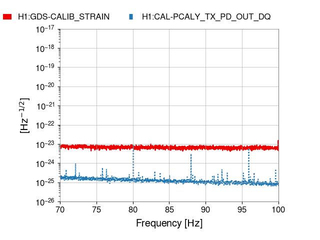
After reporting that the Pcal Y TX/RX PD noise spectrum looked quite bad with plenty of lines and comb structure, dangerously close to the CAL-DELTAL_EXTERNAL noise floor in a 100 s FFT (see LHO aLOG 48192), some hardware adjustments were made to improve the Pcal Y performance and noise spectrum (see 48206). Thank you for the fast response by Rick, Jenne, Niko, and Sharan!

While the lines in the 100 s long spectra reported in LHO aLOG 48192 were mostly below the CAL-DELTAL_EXTERNAL noise floor, longer integration times used for long-duration searches will eventually see these artifacts. These must be either followed-up in detailed post-processing studies, identified before analyses, or detection thresholds must be raised. For detailed review, see the O1/O2 lines and combs paper https://arxiv.org/abs/1801.07204.

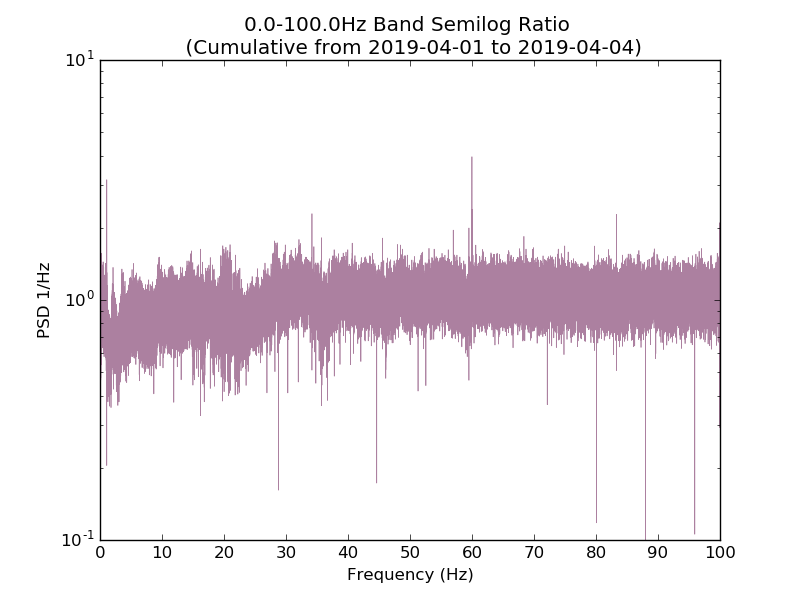
Keith has a nice tool to monitor the noise weighted 1800 s long SFTs produced by Fscan each day (see here for LHO and here for LLO). The last spectra for each day is a ratio of the current day's average ASD with the run average ASD.

I attach yesterday's ratio plot (figure 1) to show that the downward-facing "spikes" indicate reduction/mitigation of some of the lines spotted in the Pcal spectra from the first few days of the run (figure 2).

This definitely helps, thank you! Pcals should be closely monitored throughout the run so that we can either ask for further mitigation or perform triage in urgent situations.
Images attached to this report
LHO General
patrick.thomas@LIGO.ORG - posted 03:58, Friday 05 April 2019 (48255)
Ops Owl Mid Shift Status
Have remained locked and in observing.
Consistent notifications of 'ITMY mode 12 is growing!! turning off gain'. Trend (attached) does not look too bad.
H1CALCS timing bit is constantly red.
Microseism has continued to climb.
Non-image files attached to this report
LHO General
patrick.thomas@LIGO.ORG - posted 00:46, Friday 05 April 2019 (48253)
Ops Owl Shift Transition
TITLE: 04/05 Owl Shift: 07:00-15:00 UTC (00:00-08:00 PST), all times posted in UTC
STATE of H1: Observing at 111Mpc
OUTGOING OPERATOR: Cheryl
CURRENT ENVIRONMENT:
    Wind: 7mph Gusts, 6mph 5min avg
    Primary useism: 0.02 μm/s
    Secondary useism: 0.29 μm/s 
QUICK SUMMARY:

Locked and in observing. Microseism is trending up.
H1 IOO (IOO)
cheryl.vorvick@LIGO.ORG - posted 00:28, Friday 05 April 2019 (48185)
IM alignment jump in IM1, IM2, and IM3, on Feb. 12, 2019

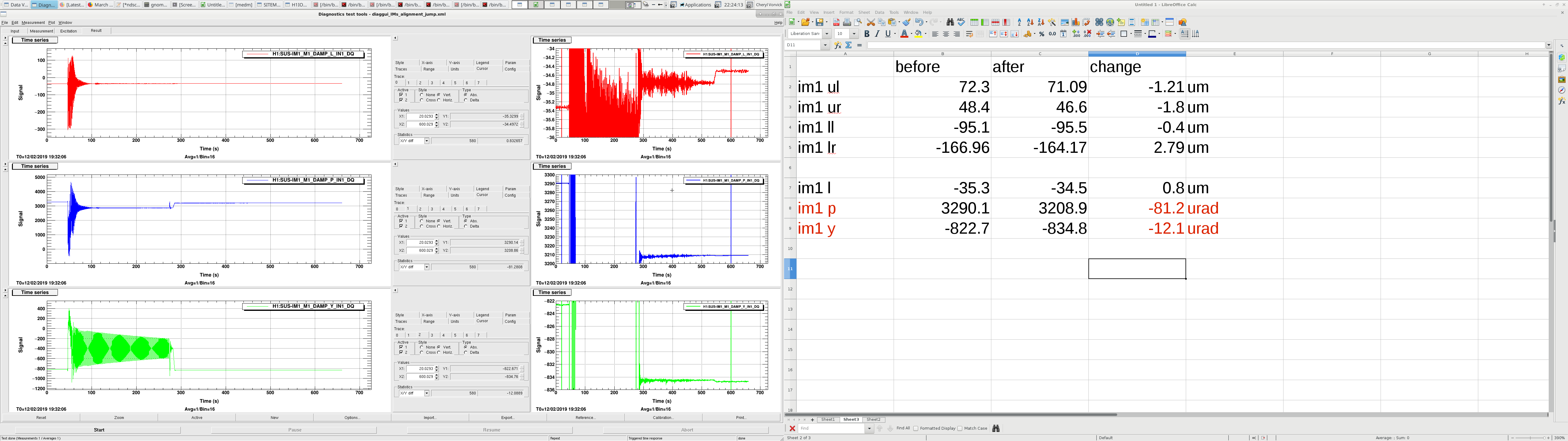
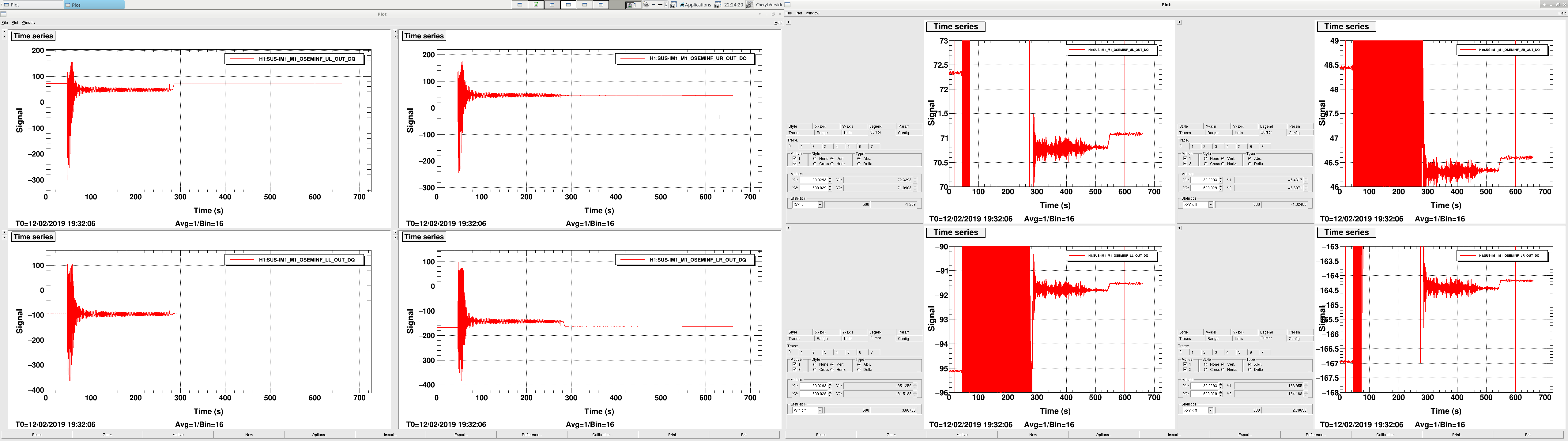
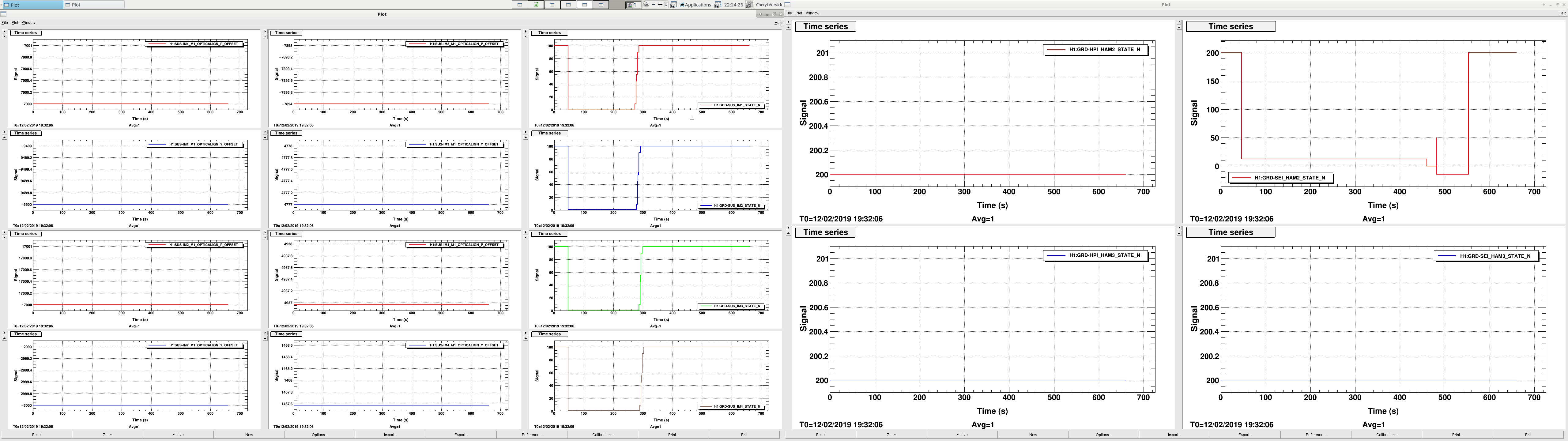
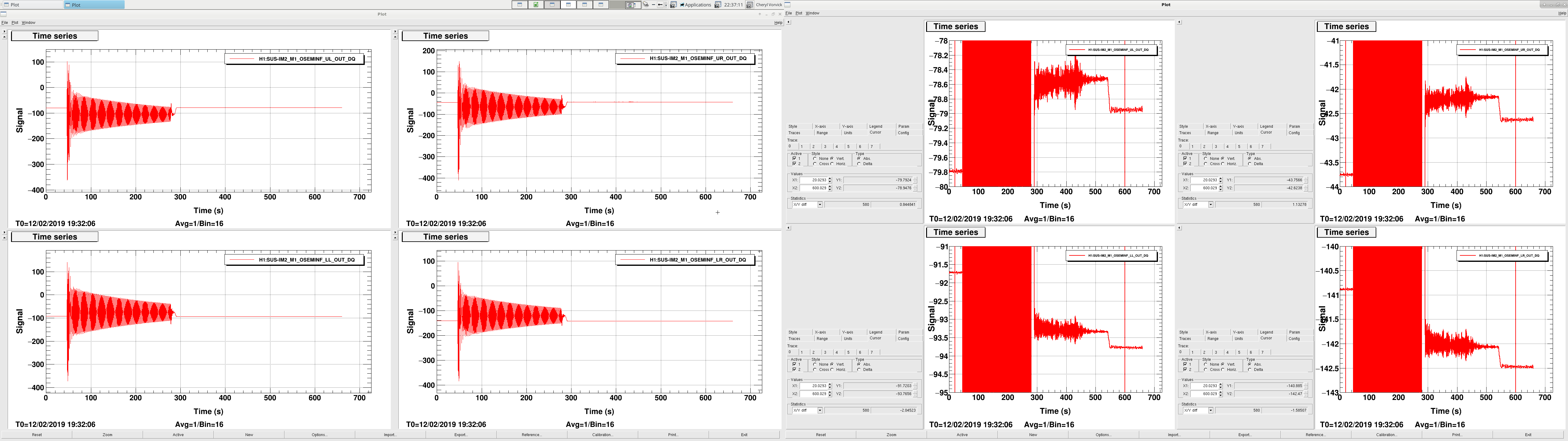
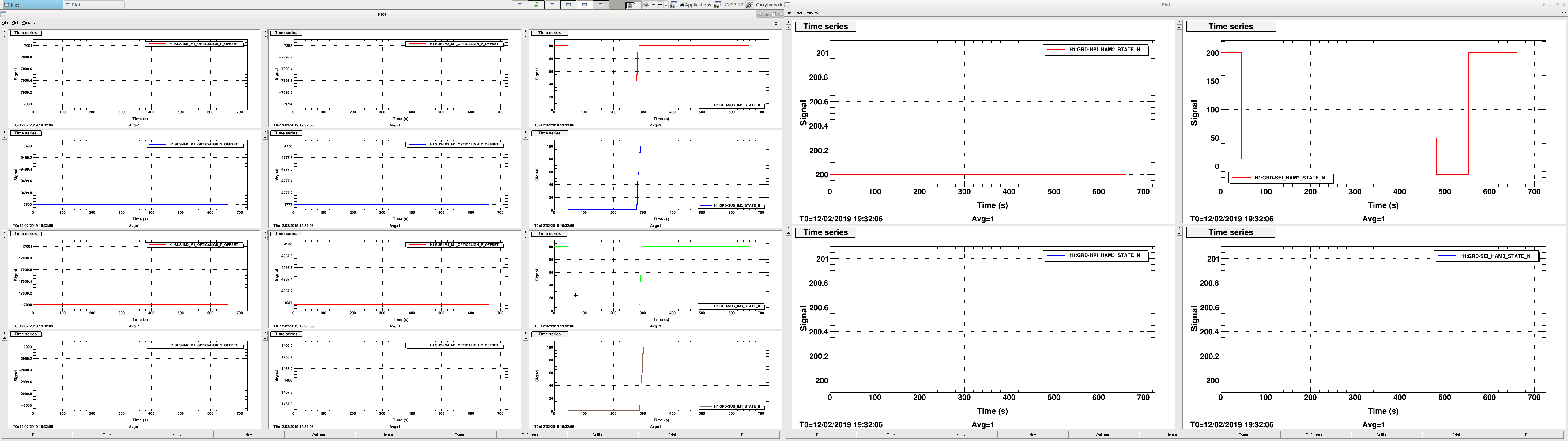
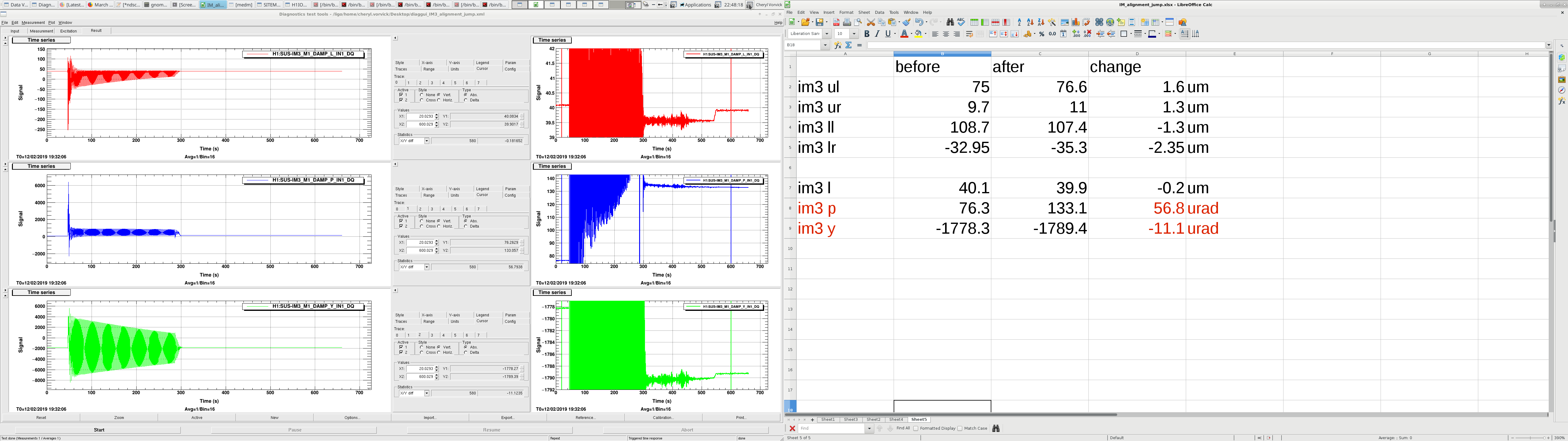
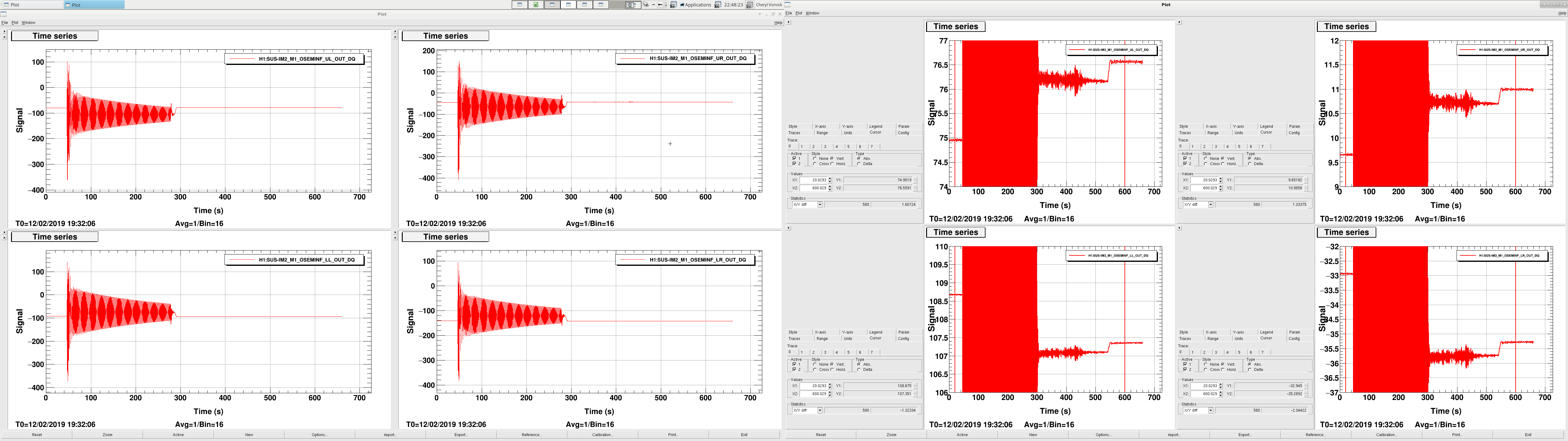
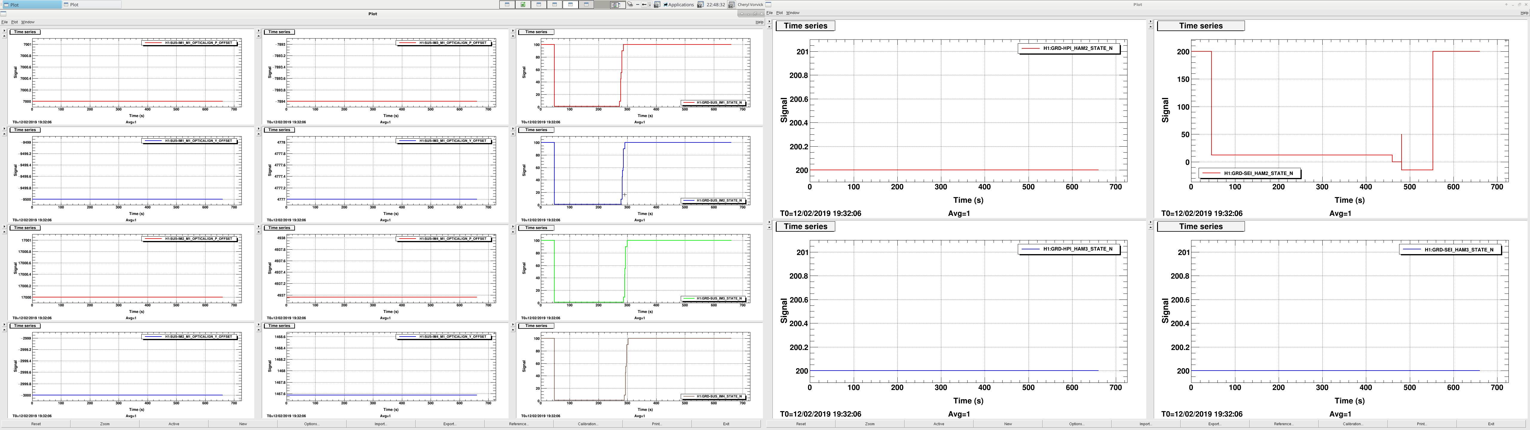
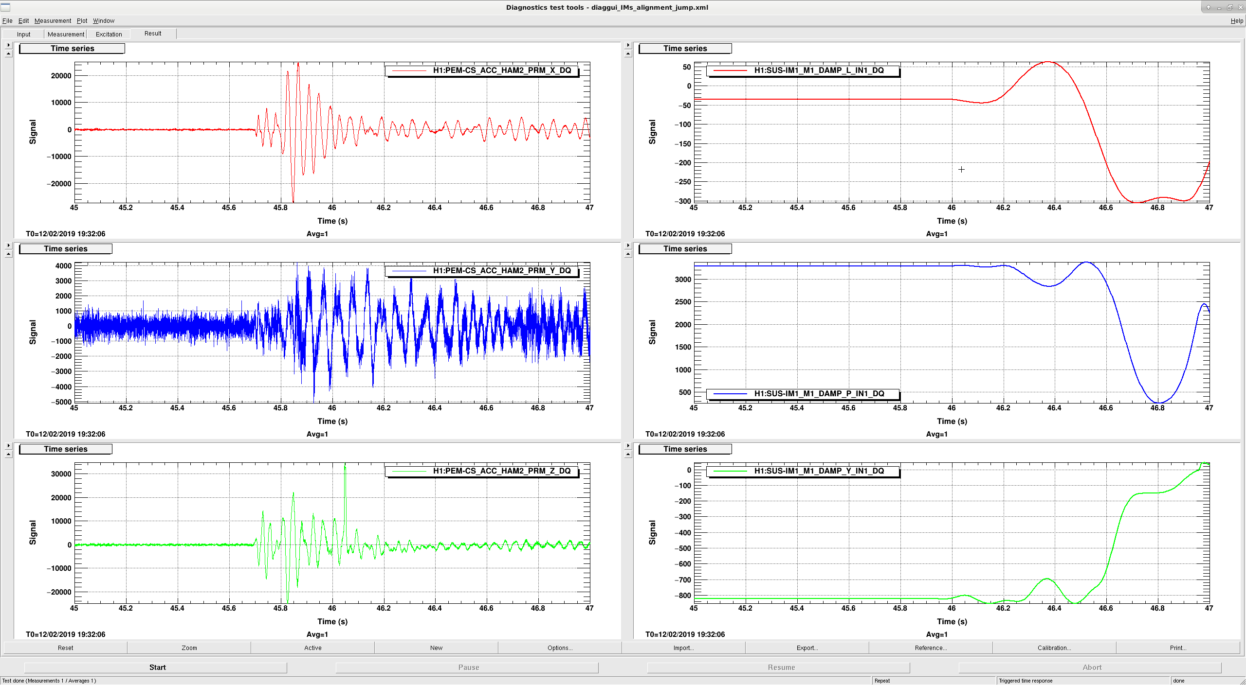
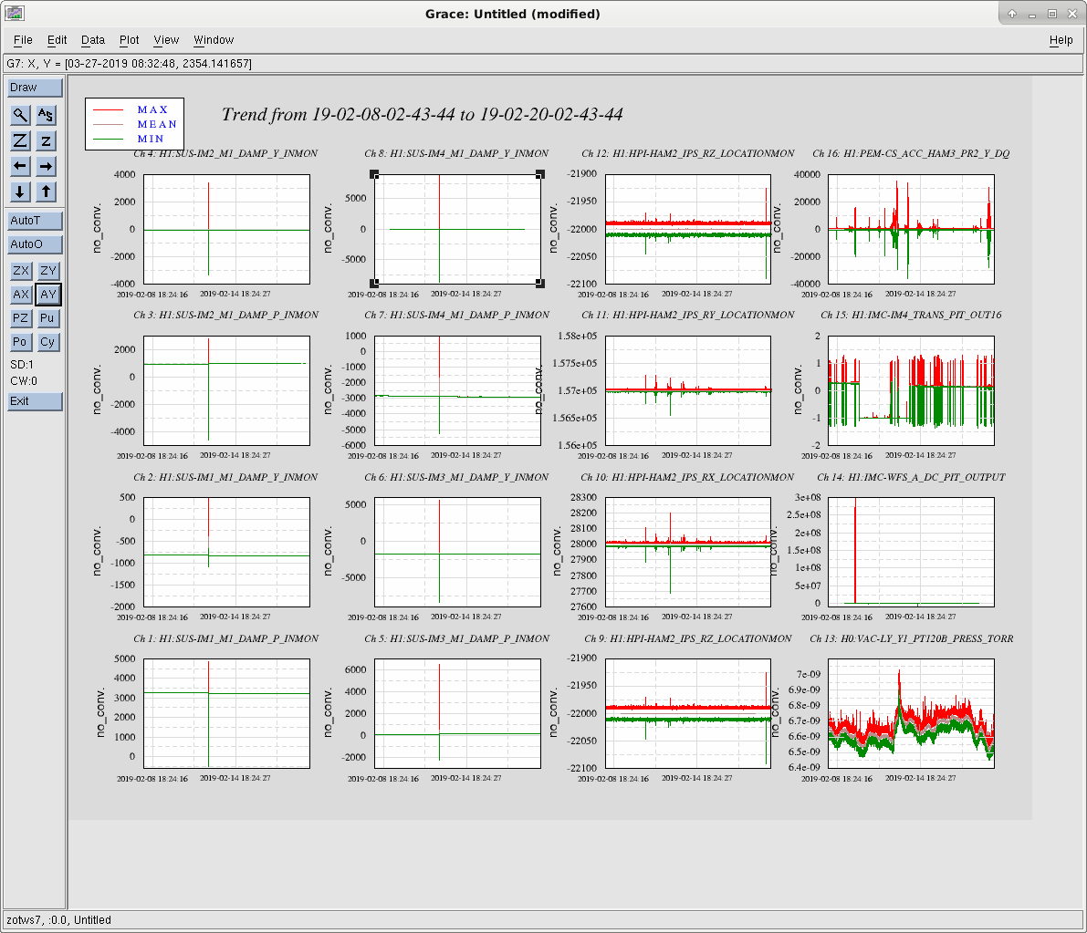
There was an event on Feb. 12, starting just after 19:31 UTC, that strongly shook the IMs in HAM2, and caused ISI and optics in HAM2 to trip, and caused alignment shifts in the IMs.  Plots attached show length, pitch, and yaw signals, and OSEM OUT signals, along with guardian states of each IM and HAM2 HEPI and ISI.

optic dof change
im1 length 0.8um
im1 pitch -81.2urad
im1 yaw -12.1urad
im2 length -0.5um
im2 pitch 48.2urad
im2 yaw 6.4urad
im3 length -0.2um
im3 pitch 56.8urad
im3 yaw -11.1urad

Adding this to FRS Ticket 4698.

Images attached to this report
H1 General
cheryl.vorvick@LIGO.ORG - posted 00:15, Friday 05 April 2019 (48252)
OPS Eve Summary:

TITLE: 04/05 Eve Shift: 23:00-07:00 UTC (16:00-00:00 PST), all times posted in UTC
STATE of H1: Observing at 111Mpc
INCOMING OPERATOR: Patrick
SHIFT SUMMARY: quiet, SQZ unlocked one time, relocked and H1 back in Observe
LOG:

Images attached to this report
H1 CAL (ISC)
sheila.dwyer@LIGO.ORG - posted 17:02, Thursday 04 April 2019 (48250)
PUM cross over measurement, sweeps from last night

We took some calibration time today to measure the cross over between the PUM and test mass by exciting the L2LOCK filter.  (the PUM and test paths are dominating the response function at frequencies where our calibration is wrong, so it seemed like a good idea to make an independent measurement of this.)

The first attached pdf shows this measurement compared to a model of -C*D*(PUM+UIM)/(1+CDTST) which is In1/In2, as well as the ratio of PUM+UIM/TST, which this is an approximation of. The coherence of the measurement wasn't great, so it might be useful to retake this with more coherence and extend the measurement to lower frequencies.  This measurement would indicate that the cross over is quite stable, but we saw last week that the addition of a 4.5Hz boost makes this unstable at 8Hz (without the L2A decoupling on) 47982

Also attached are the plots produced by pyDARM based on the calibration sweeps taken last night after the pcal fix 48206.  These measurements give slightly different fitting results from the set of sweeps taken from March 27th to 31st, but the differences aren't enough to make much of a difference in our overall calibration. 

Non-image files attached to this report
H1 GRD (CDS)
thomas.shaffer@LIGO.ORG - posted 16:33, Thursday 04 April 2019 - last comment - 17:12, Thursday 04 April 2019(48248)
h1guardian1 memory leak narrowed down

I narrowed down the location of the memory leak that was found last week (alog47903).

The decorator, mentioned in previous alogs, was instantiating a LIGOBlendManger (LBM) object with every loop of the run method. Not great practice, I know, but it was much easier to create and maintain this way.  When initializing a LBM object, it will set up some ezcaPVs, set up attributes to be called later, and set an ezca.ramp Ramp object that can be called to start the transitioning of the blend filters. The last one is where the leak has been narrowed to (lines 105-109 in (userapps)/isi/common/isiguardianlib/blend/ligoblend.py).

My theory: Somehow ezca is keeping a new record for each one of these Ramps created on each initialization, instead of the usual reference cycling.


To test this I ran bits of code in different ipython shell environments and watched htop to look at my local machine's memory. (Thanks Jonathan!) If you want to know more about what exactly I did, or are me in the future trying to remember, I attached a .py file of what I did and you can read each test case.

Non-image files attached to this report
Comments related to this report
jameson.rollins@LIGO.ORG - 17:12, Thursday 04 April 2019 (48251)

For the record, there's nothing at all inherently wrong with initializing a class within every loop.  Whether or not that's problematic depends entirely upon what happens during the initialization.  If the initialization is creating objects that are not being properly cleaned up then that may be an issue.

H1 CAL
sheila.dwyer@LIGO.ORG - posted 18:00, Tuesday 02 April 2019 - last comment - 20:57, Friday 05 April 2019(48178)
changes to pcal correction and delay in sensing measurement processing function, fixed error in DARM filter model

J Kissel, S Dwyer

We spent some time looking at sensing.py today, trying to understand better the systematic error in our sensing function model used for fitting the sensing function measurement.

Pcal Correction:

We also noticed that there is something called OMCDelay (and IOP delay which is insidetotalSensingDigital ) applied in Pcal correction, at first glace it doesn't seem right to apply an OMCDelay here. The default value of both of these delays is 0, and we think that omcDelay was intended to be a delay from sending pCal from the end station to  CalCS model in the corner.  Jeff filed a ticket : 12638  Since both of these are set to 0 delay, they don't impact the systematic error in the sensing or actuation functions. 

DARM excitation delay:

We committed this version of sensing.py at 7121.

DARM filters:

Non-image files attached to this report
Comments related to this report
ling.sun@LIGO.ORG - 10:14, Thursday 04 April 2019 (48240)

Lilli S, Jenne D, Jeff K,

I found the alog documenting when the DARM1 FM3 (resG) filter was turned on (47235). Jenne checked the exact time when the filter was turned on.

2019 Mar 01 23:38:37 UTC -- FM3 was turned on for the first time

2019 Mar 02 03:07-04:02 UTC -- It seems that during this period the filter was turned off again for some calibration testing.

I noticed that there was a measurement template during this time period: /ligo/svncommon/CalSVN/aligocalibration/trunk/Runs/O3/H1/Measurements/FullIFOSensingTFs/2019-03-01_H1_PCAL2DARM_TF_5t1100Hz_8min_AFTER_CHANGE.xml (2019-03-02 03:26:24 UTC)

It is not clear whether the model file modelparams_H1_20190301.py was generated using the measurements when FM3 was on or off. But for all the model files generated after Mar 01, I have added FM3 to the DARM1 filter bank.

sheila.dwyer@LIGO.ORG - 11:17, Friday 05 April 2019 (48265)

We have removed the excitation delay from the DARM EXC/ DARM IN2 measurement processing in sensing.py, because we think this was an error after Jenne looked into it more.  This will make our sensing function fit even worse, like the second attachment above.  

sensing.py is committed at revision 7143

jeffrey.kissel@LIGO.ORG - 20:57, Friday 05 April 2019 (48272)
J. Driggers, J. Kissel, L. Sun

TL;DR -- We also reverted the application of the full pcalCorrection mentioned above today, but now I think there's a bug in the way that the DC gain of the analog anti-aliasing filters (which is 0.99) are applied.

Here's why (as we were reminded by Evan and Shivaraj, but only just finally grokked today):

We take two measurements to obtain a complete measurement of the interferometer's response to differential arm displacement, C_meas,

  DARM_IN1       C_truth      (artifacts in PCAL_RXPD)
 ---------- = ------------- * -----------------------
 PCAL_RXPD    (1 + G)_truth   (artifacts in DARM loop)

  DARM_EXC                     
  --------  = (1 + G)_truth * (artifacts in DARM loop)
  DARM_IN2                  
which, as is indicated above, have some artifacts for which we need to correct.
When we multiply these together, the (artifacts in DARM loop) cancel, leaving

 DARM_IN1      DARM_EXC                            
 --------   *  --------  =  C_truth  *  (artifacts in PCAL_RXPD)
 PCAL_RXPD     DARM_IN2  

Now, we want to isolate C_truth. 

We know that (artifacts in PCAL_RXPD) are what we need to apply to turn the PCAL *channel* back in to DARM displacement,

(artifacts in PCAL_RXPD) = armSign_PCAL * (two poles at 1 Hz) * 1/(PCAL analog AA filter) * 1/(PCAL digital 65k-16k down sampling filter)

                         = armSign_PCAL * ("pcal dewhitening")* 1/(AAanalog_PCAL response * AAanalog_PCAL DC gain) * 1/(AAdigital_PCAL)

where AAanalog_PCAL has been measured to have a DC gain of 0.99 (import later), and AAdigital is a digital filter provided by the RCG with a DC gain of 1.00.

Thus, to get at C_meas alone, we take our two measured transfer functions and divide it by our known "pcalCorrection,"

 DARM_IN1      DARM_EXC                              armSign_PCAL * (two poles at 1 Hz)                       
 --------   *  --------  = C_truth * ----------------------------------------------------------------
 PCAL_RXPD     DARM_IN2             (AAanalog_PCAL response * AAanalog_PCAL DC gain) * AAdigital_PCAL 


           DARM_IN1      DARM_EXC      (AAanalog_PCAL response * AAanalog_PCAL DC gain) * AAdigial_PCAL                        
C_truth =  --------   *  --------  *   ----------------------------------------------------------------
           PCAL_RXPD     DARM_IN2                    armSign_PCAL *  (two poles at 1 Hz)   

We also have a model of this measurement of C_truth, which includes,

C_model =   (Optical Response = optical spring * coupled cavity pole) 
          * (Optical Gain) 
          * (IFO delay = (L/c) * single pole correction) 
          * (Uncompensated high frequency OMC DCPD Trans. Impedance Amp and Analog Whitening Filter Poles) 
          * (OMC DCPD analog AA filter response) * (OMC DCPD analog AA filter gain) 
          * ADC Gain 
          * (OMC DCPD digital 65k-16k down sampling filter)

where the (Optical Response) and (Optical Gain) are the only things we *don't* know or can't measure on the bench. We also *choose* to empirically measure the overall gain, from physical DARM displacement to DARM_IN1 counts, because it's easier to do that than measure the gains of all the electronics (i.e. the trans impedance amp, the whitening chassis, the analog AA, and other things between the "ideal" optical gain and the OMC DCPDs, i.e. between the power coming out of the SRC and the power on the DCPDs), because we can get very precise answer without uncertainty build-up from each term.
So, 
(overall gain) =   (Optical Gain [W/m]) 
                 * (loss between SRM to OMC DCPDs [W/W]) 
                 * (DCPD QE [A/W]) 
                 * (Trans. Impedance Gain [V/A]) 
                 * (Whitening Gain [V/V]) 
                 * (OMC analog AA Gain [V/V]) 
                 * (ADC gain [ct/ V]) 
                 * (whatever digital gains folks have implemented between the ADC channel and DARM_IN1 [ct/ct])

(and, of course, there are two DCPDs, so it's actually the split gain of the two paths recombined digitally in the real-time system, but you get the idea -- we want to fit for the gain of the whole path -- including the OMC DCPD's Analog AA filter gain.)

So we create a multi-parameter MCMC fit on C_truth to obtain the (overall gain) and (overall gain) but that means we must take out everything that we know, i.e.

C_MCMCinput = (Optical Response) * (overall gain) 
            = C_truth / (IFO delay * high freq. DCPD poles * AAanalog_DCPD response * AAdigital_DCPD)

Now here's where things get SNEAKY and CONFUSING.
     (1) We only have one model for the analogAA that we use for both the PCAL and the OMC DCPDs. Thus, analogAA_PCAL = analogAA_DCPD.
     (2) The RCG is doing identically the same thing for the digitalAA. Thus, digitalAA_PCAL = digitalAA_DCPD
That means that technically, we'd have to do *less* to create C_MCMCinput, because the (analogAA_PCAL * digitalAA_PCAL) from pcalCorrection cancel the (analogAA_DPCD * digitalAA_DCPD),

                                                         1
C_MCMCinput = C_truth * -----------------------------------------------------------------------------
                       (IFO delay * high freq. DCPD poles * AAanalog_DCPD response  * AAdigital_DCPD)  


               DARM_IN1      DARM_EXC      (AAanalog_PCAL response * AAanalog_PCAL DC gain) * AAdigial_PCAL                                      1
C_MCMCinput =  --------   *  --------  *   -----------------------------------------------------------------  *  -----------------------------------------------------------------------------
               PCAL_RXPD     DARM_IN2                       armSign_PCAL * (two poles at 1 Hz)                   (IFO delay * high freq. DCPD poles * AAanalog_DCPD response  * AAdigital_DCPD)    


               DARM_IN1      DARM_EXC                  (AAanalog_PCAL response * AAanalog_PCAL DC gain) * AAdigial_PCAL                                                  
C_MCMCinput =  --------   *  --------  *   -------------------------------------------------------------------------------------------------------------
               PCAL_RXPD     DARM_IN2      armSign_PCAL * (two poles at 1 Hz) * IFO delay * high freq. DCPD poles * AAanalog_DCPD response * AAdigital_DCPD  


               DARM_IN1      DARM_EXC                             AAanalog_PCAL DC gain              
C_MCMCinput =  --------   *  --------  *   ------------------------------------------------------------------------
               PCAL_RXPD     DARM_IN2       armSign_PCAL *  (two poles at 1 Hz) * IFO delay * high freq. DCPD poles

So -- you can get away with *only* dividing the measurement by *only* the frequency response (two poles at 1 Hz) and the (high freq. DCPD poles), which is what pyDARM was doing before, we just didn't realize it.. Note, I think pyDARM is still missing the IFO delay, but this works out to be 1 [us], so a small error on top of much bigger impactful things. By applying the full pcalCorrection, we were double counting the analogAA and digitalAA.

Note above, we're left with AAanalog_PCAL DC gain because we've chosen to fold the gain of the OMC DCPD analog AA into the fit of the overall gain.
I would have not have done this sneaky cancellation business, because there's confusion on the way -- BUT the math above gets you the true (overall gain) of the sensing function and the true (optical response).

BUT the DC Gain of the AAanalog_PCAL is not multiplied, it's divided, in pyDARM and I think it results in a missing multiplicative factor of AAanalog_PCAL DC gain = 0.99 in the construction of 1/C_GDS:
     (3) Again, the DC gain of *one* of analogAA models is *divided not multiplied* out of the what is input to the MCMC, and thus
     (4) The "optical gain" max aposteriori (MAP) that is spit out of the MCMC is then a fit to (overall gain) / (analogAA DC gain)^2.
AND
     (5) The user receives information to install 1/MAP into foton for the CAL-CS version of the 1/C correction, so this is wrong by (analogAA DC gain)^2 / (overall gain),
     (6) The sensing function model is reconstructed, it's done with the (overall gain) / (analogAA DC gain)^2 AND *one* of the analog models multiplied in *WITH ITS DC GAIN,* so we get model of C with (overall gain) / (analogAA DC gain), which means comparisons between (the MCMC input / model) are showing (overall gain) / (analogAA DC gain)^3,
     (7) gds corrections for the sensing function are *re*created ( from scratch without the model from (5) ), it's also created with *one* of the analog models *WITH ITS DC GAIN* multiplied, in so GDS corrections to C are 1 / (analogAA DC gain), and thus
     (8) 1/C_GDS = (analogAA DC gain) / C_truth

Let's look at 
    ^/trunk/Common/pyDARM/src/sensing.py   rev 7146

Inside the function "process_sensing_measurements,"

Lines 325-327      PCAL_tf = DARM_IN1 / PCAL_RXPD # essentially, later filtered for coherence, but overwritten with the same name
Lines 334-336       CLG_tf = DARM_EXC / DARM_IN1 # essentially, later filtered for coherence, but overwritten with the same name

Line 361           if modelAndDataPars[n].PCAL_arm == 'Y': sign = -1 # armSign_PCAL from above

                   # Here's where (3) gets applied
                   #                           armSign_PCAL       /        (two poles at 1 Hz)                           /               AAanalog_PCAL DC gain
Line 376           C_meas = PCAL_tf * CLG_tf * sign / signal.freqresp(sensProd.pcaldewhitening, 2.0*np.pi*PCAL_f)[1] / abs(signal.freqresp(sensProd.AAanalog, 2.0*np.pi*0.01)[1])
       
                   #              from above  /           high freq. DCPD poles
Line 380           opticalResponse = C_meas / signal.freqresp(sensProd.uncompensatedOMCDCPD, 2.0*np.pi*PCAL_f)[1]

and opticalResponse (assuming we don't correct for time dependence) is what's input into the MCMC fitting code because (in the same function), the named tuple "results" has its second slot filled with "opticalResponse",
Line 643           thisresult = results(PCAL_f, opticalResponse, unc, err, opticalResponse_mAperpm, err_mAperpm, opticalResponse_ref_tf)
Line 644           allresults.append(thisresult)

and then we zoom down to the function that runs the MCMC fitting, called sensing_MCMC, in which this "opticalResponse" is shoved into the MCMC hammer, 
Line 860           sampler = emcee.EnsembleSampler(nwalkers, ndim, lnprob_antispring, args=(PCAL_f, opticalResponse, err), threads=3)

from which the first of the maximum aposteriori values (MAP) values returned are the "optical gain," which we now know is (overall gain) / (analogAA DC gain)^2.
This MAP values is the "optical gain" that we stick in to any updated parameter file.

For CAL-CS, we just install the inverse of the "optical gain" MAP value, which we now know is (analogAA DC gain)^2 / (overall gain).

Then, this parameter file is used as input *back* in to sensing.py, where C_model is created that is eventually used to create filters for GDS. Here, the analogAA filter is multiplied back in *with its DC Gain*. See
Line 229          # FIXME the variable below is NAMED INCORRECTLY. It's actually C not 1/C. JSK 2019-04-04
Line 237          # gdscorrection = 1/ calcsResid2gdsInvSensOut = 1 / ( 1/C_pyDARM / 1/C_foton ) = (C_pyDARM / C_foton)
Line 238          calcsResid2gdsInvSensOut = signal.freqresp(serielZPK(serielZPK(uncompensatedOMCDCPD, AAanalog), omcDCPDtf), 2.0*np.pi*freq)[1] * AAanalog_delay   # analogAA is multiplied in WITH ITS DC GAIN
Line 239             * delay * singlePoleApproxDelayCorrection 
Line 240             * totalSensingDigital_freqresp 
Line 241             * 1.0/signal.dfreqresp(signal.ZerosPolesGain([],np.zeros(1),1,dt=1.0/2**14), 2.0*np.pi*freq/2**14)[1]  
Line 242             * pars.sensingSign 
Line 243             / IIRwarp_interp   

And this multiplied on to the data stream as 1/calcsResid2gdsInvSensOut (see res_corr_model on line 65 of GDS_FIR_filter_generation.py), so we have
     1                   1                  (analogAA DC gain)^2            1             (analogAA DC gain)
----------- * ------------------------  =   -------------------- *  ------------------ =  ------------------
 MAP value    calcsResid2gdsInvSensOut        (overall gain)        (analogAA DC gain)      (overall gain) 

Which means that at high frequency, GDS, is spitting out 0.99 / C_truth.

Also note that when the pcal correction is created, it's created *WITHOUT THE AA's DC GAIN,
    From above
    pcalCorrection = armSign_PCAL * ("pcal dewhitening")* 1/(AAanalog_PCAL response * AAanalog_PCAL DC gain) * 1/(AAdigital_PCAL)
and yet Line 208 (split for better labeling of parts) of sensing.py is
#                                     ("pcal dewhitening")           /               AAanalog_PCAL response                       /                 AAanalog_PCAL DC gainA           *         Adigital_PCAL        *  delay resolves to 0
pcalCorrection = signal.freqresp(pcaldewhitening, 2.0*np.pi*freq)[1] / (signal.freqresp(AAanalog, 2.0*np.pi*freq)[1]*AAanalog_delay/abs(signal.freqresp(AAanalog, 2.0*np.pi*0.01)[1]) * totalSensingDigital_freqresp * omcDelay_freqresp)


It's quite a kerfuffle. I've opened an FRS ticket for us to solve this issue -- see IIET Ticket 12642.

H1 ISC (DetChar, ISC, SQZ)
anamaria.effler@LIGO.ORG - posted 04:29, Monday 18 March 2019 - last comment - 08:54, Friday 05 April 2019(47606)
36W lock

Dan, Craig, Georgia, Alexei, Anamaria

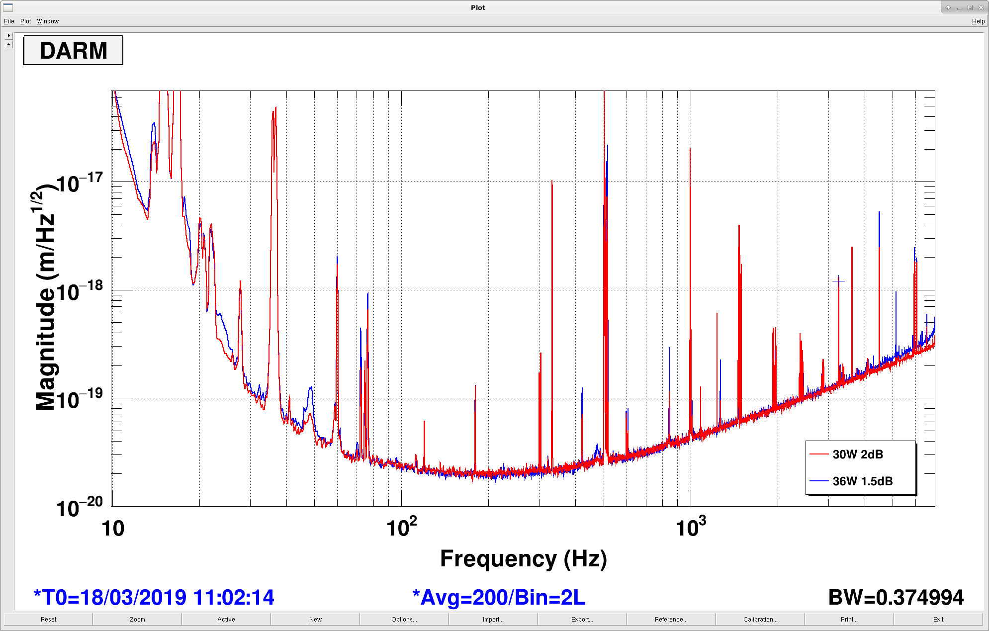
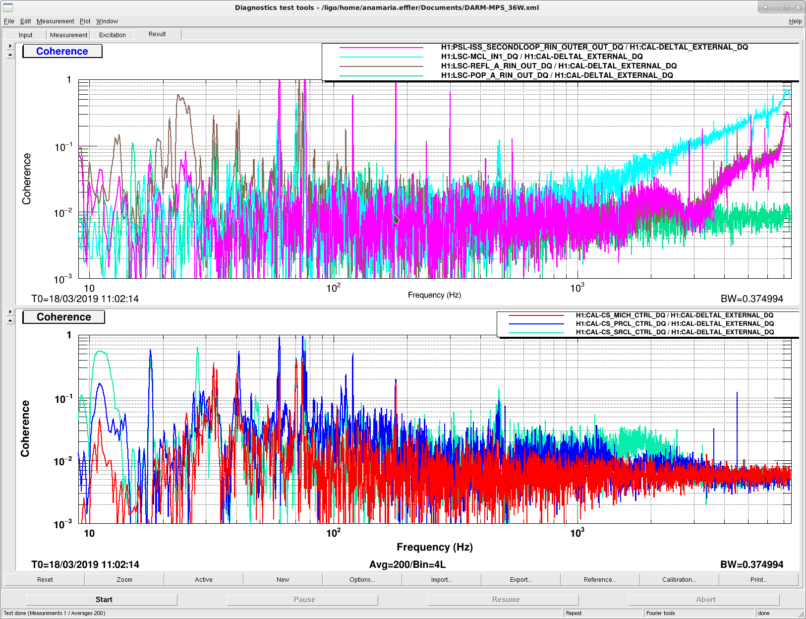
We decided to try a higher power lock now that a lot of things have been smoothed out. We were able to easily power up to 36W (we did it at the POWER_30W step, before low noise ASC settings and ESD). We ran two sets of lines, low frequency and high frequency for intensity and frequency noise coupling. We also ran a 9 MHz EOM line.

- For a while we ran without ISS DC_COUPLED for unrelated reasons, but once Georgia engaged it the ISS line at 70ish MHz was reduced by a factor of 10.

- We paranoidly increased the PRCL gain from 12 to 15, reduced MICH P gain from -1.2 to -1 and reduced CHARD P from 2.0 to 1.8. Unclear if it was necessary.

- We set the SRCL length offset to what Sheila had chosen earlier for optimized squeezing, but we were only able to get 1.5 dB instead of the 2 dB she had. We didn't try to optimize anything about it.

- We raised the CM gain 3dB and saw the DARM noise at high frequency get reduced some. We could try more maybe, but we should measure the loop.

- We overall lost 4% of optical gain (says maybe-ok-kappaC) but we recovered 1% with a bit of spot move (Dan will post details). We put this into CAL DARM ERR and ran a pcal broadband to confirm the calibration was correct.

- Some numbers:
Optical gain decrease: 3%
PRG decrease: 3.3%
X arm increase: 17%
Y arm increase: 16%
AS_C increase: 16%
REFL increase: 8%
POP 18 decrease: 6%
POP90 decrease: 4%

- The ISS low frequency line increased by x1.4 but the high frequency line did not change.
- The frequency noise low frequency line did not change, but the high frequency line increased by x2.2. This is good because it means we did not make the frequency noise worse in the bucket.
- The 9 MHz line at 72.3 Hz increased by x2.4. Hopefully we can tune this coupling back down.

- The noise at the 48 Hz bump and maybe in the 20-35 Hz range is a bit worse, but the overall noise is quite comparable to the fully tuned 30W state.

We think that with some TCS tuning (we did none so far!) and squeezer re-optimization we can surpass the 30W performance.

Images attached to this report
Comments related to this report
georgia.mansell@LIGO.ORG - 04:39, Monday 18 March 2019 (47607)

Note on ISS 2nd loop DC coupling:

The first time we tried going through LASER_NOISE_SUPPRESSION at 36W we had an aggressive excitation on the ISS 2nd loop. This meant when the second loop was DC coupled the output of the AC coupling servo was held at a large value and pushed the ISS diffracted power to zero, causing almost-instant lockloss. Lesson learnt: do not try to DC couple the ISS with a big excitation.

The second time time we went to ISS_DC_COUPLED we lowered some gains to compensate for the extra power:
- PSL-ISS_SECONDLOOP_REFERENCE_IN_MTRX_1_4 was 125 (from 150 @30W)
- lscparams.ISS_FinalGain was 5 dB (from 7dB @30W).


DC coupling was seamlessly engaged. For future commissioners: I have returned the parameters to their 30W values in guardian, and the has been loaded.

craig.cahillane@LIGO.ORG - 04:46, Monday 18 March 2019 (47608)
DARM plant flips back to antispring detuning with 36 W and SR3 heater on at 5W.  This could be why our range did not improve as much as hoped. See 47604
Non-image files attached to this comment
daniel.brown@LIGO.ORG - 04:55, Monday 18 March 2019 (47609)

After some spot moves we managed to max out the arm powers with 181kW and 167kW in Y and X respectively, up ~2kW.

Mirror P2L start P2L end Y2L start Y2L end
ITMX -3.98 -3.6 0.26 -0.02
ITMY -3 -2.6 -0.2 0
ETMX 4 4.98 4.0 5.1
ETMY 4.5 4.7 2.5 2.18

The largest change was in ETMX yaw position, which moved slightly further away from the point absorber there. This is where we gained the most. The spots moved down slightly on the ITMY point absorber. I thought I had some nice HWS images of the ETMX point absorber reducing, however it was being ruined by a dead pixel.

I also tried a brief SR3 heater test. For the whole 36W test the heater was at 5W. I dropped it to zero for 20 minutes but the RF18 dropped very quick, from 47 to 44. This was preceded an ADS instability at 0.012Hz, it was stopped by just switching off all the ADS channels, however switching them back on results in the the instability ringing back up. Given that I didn't tune any of the TCS for 36W yet, it's no surprise that 9MHz is affected by SR3 due to too much cross coupling from PRCL to SRCL.

Hopefully these new spot positions work at the usual 30W settings tomorrow. I have left ADS off, some residual of the 0.012Hz oscillation is still visible, we'll see if it survives the night...

jenne.driggers@LIGO.ORG - 08:54, Friday 05 April 2019 (48261)

Since the beam spot 'positions' in Dan's alog are quoted in A2L gain numbers, here I tabulate what that means for spot position in mm.  Note that I am quoting today's current values for the A2L gains, which differ very slightly from those quoted above. 

Sign convention for spot position in mm: up (+Vert on SUS screens) is positive for pitch and farther to the left (+Trans on SUS screens) is positive for yaw.

  Pit P2L gain Pit [mm] Yaw Y2L gain Yaw [mm]
ITMX -3.76 20.8 -0.17 -0.6
ITMY -2.6 15.6 0.0 0
ETMX 4.85 -18.3 4.95 18.2
ETMY 4.55 -16.9 2.03 7.5


Displaying reports 41921-41940 of 88748.Go to page Start 2093 2094 2095 2096 2097 2098 2099 2100 2101 End