Here are the estimates of the overall systematic error in the response function due to systematic errors in 1) PUM actuator and 2) Sensing function. Firstly I copied the status summary from Jeff's alog 47941
1) PUM actuator systematic error
- The PUM actuator systematic error remains below 20 Hz. We've identified that it's parasitic length drive not accounted for through L2A / A2L. This is prominent because the IFO spot positions on ETMX are -18 +/- 0.2 mm in pitch (-vertical) and 18 mm +/- 0.2 in yaw (+transverse) off from the center. (note for PCAL team -- ETMY spot positions: -17 +/- 0.2 mm (-vertical) and 7.5 +/- 0.2 mm (+transverse))
The PUM results are briefly discussed in 47926. See the first pdf attachment. Page 1 and 2 show the measurements taken from drivealign bank and test bank, respectively, against the model. The fitting through the test bank is better, but the measurements from the drivealign bank are the reality. Page 3 shows the comparison of the contributions from the residuals to the overall response function, which is produced in the following way:
1) Create two separate reference models for drivealign and test scenarios, based on the Mar 16 model, by writing back the MCMC PUM MAP values.
2) Compute the error residuals for two scenarios separately.
3) Plot Response_drivealign_with_error/Response_drivealign_ref, and Response_test_with_error/Response_test_ref.
To improve this, we need to either make the physical actuator better by removing the existing features in the measurements, or update the model to compensate the features. Since it only impacts freq lower than ~20Hz, we decide to work on this improvement at a later time.
Measurements were taken on Mar 26 (in /ligo/svncommon/CalSVN/aligocalibration/trunk/Runs/O3/H1/Measurements/FullIFOActuationTFs)
Script used to generate the plots: /ligo/svncommon/CalSVN/aligocalibration/trunk/Runs/O3/H1/Scripts/FullIFOActuationTFs/compare_drivealign_vs_test.py
2) Sensing systematic error
- We have a prominent detuning below 20 Hz, and it's pro-spring. The fit to and implementation of compensation for a pro-spring is still in it's infancy, so it is under-reporting the frequency -- it's measured to be about 6.5 Hz, but the fit claims 3.7 Hz. The systematic error induced by this flaw is small above 20 Hz.
See the second pdf attachment. The first plot shows the measurement and the reference model. The second plot shows the residual contribution in the overall response function. Generally it is okay above 20Hz. One data point at about 150Hz produces a larger error. We probably will add more points around that freq for next measurement. Since the main contribution is also below ~20Hz, it does not prevent us from moving forward to update CAL-CS, etc at the moment.
Sensing measurements were taken on Mar 27 (in /ligo/svncommon/CalSVN/aligocalibration/trunk/Runs/O3/H1/Measurements/FullIFOSensingTFs)
Script used to generate the plots: /ligo/svncommon/CalSVN/aligocalibration/trunk/Runs/O3/H1/Scripts/FullIFOSensingTFs/process_sensingmeas_20190327_contribution.py
Note: To generate these contribution plots, I need the intermediate data (measurements and the TFs computed from ref models) from processing actuation and sensing. Hence I have modified actuation.py and sensing.py, adding the intermediate data into the results structure returned from these functions.
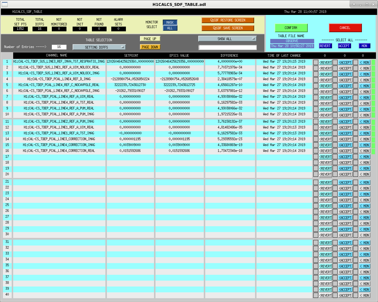
J. Kissel SDF is still having problems comparing / checking very small or very large EPICs records. This is usually exposed in the calibration group's "epics records" i.e. DARM loop model parameters at a reference time used to compute time-dependent correction factors, which are typically very small or very large -- in the 10^-17 levels or 10^+18 levels (see attached). It's unclear *when* exactly the claimed differences happen (maybe when the .snap comparison file is changed from safe to OBSERVE? Or maybe because when you *accept* the diffs, they're written at a lower precision than that comparison is made?), but it's something we're having to constantly reconcile before every observation stretch these days.
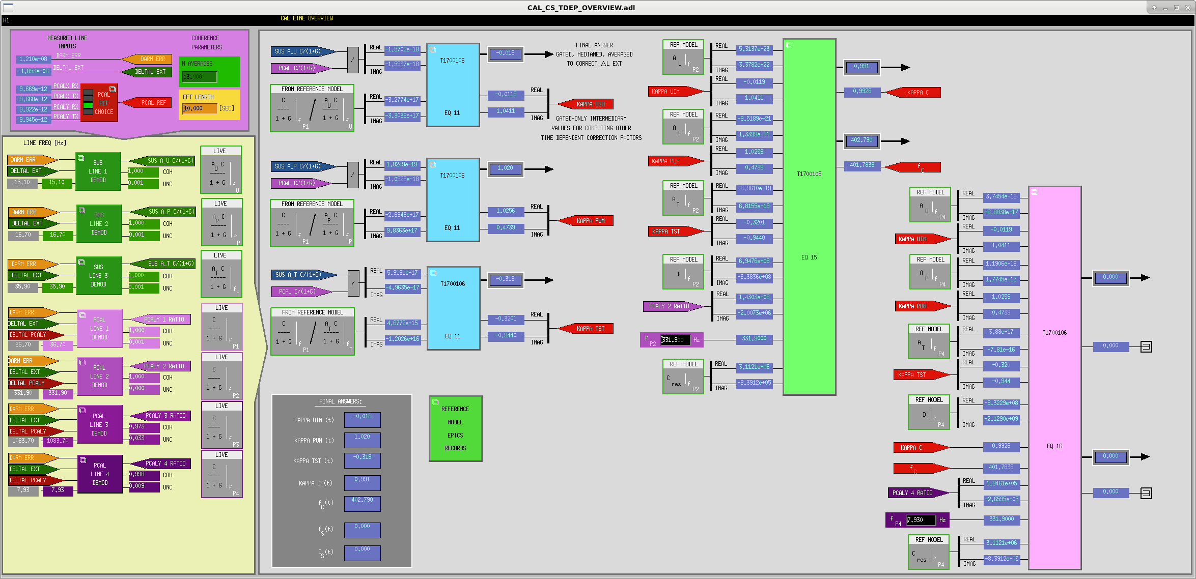
While trying to debug what's wrong with our time dependent correction factors, we found a few minor bugs in the MEDM screens:
- T1700106 was incorrectly referenced in the TDEP overview,
/opt/rtcds/userapps/release/cal/common/medm/
CAL_CS_TDEP_OVERVIEW.adl
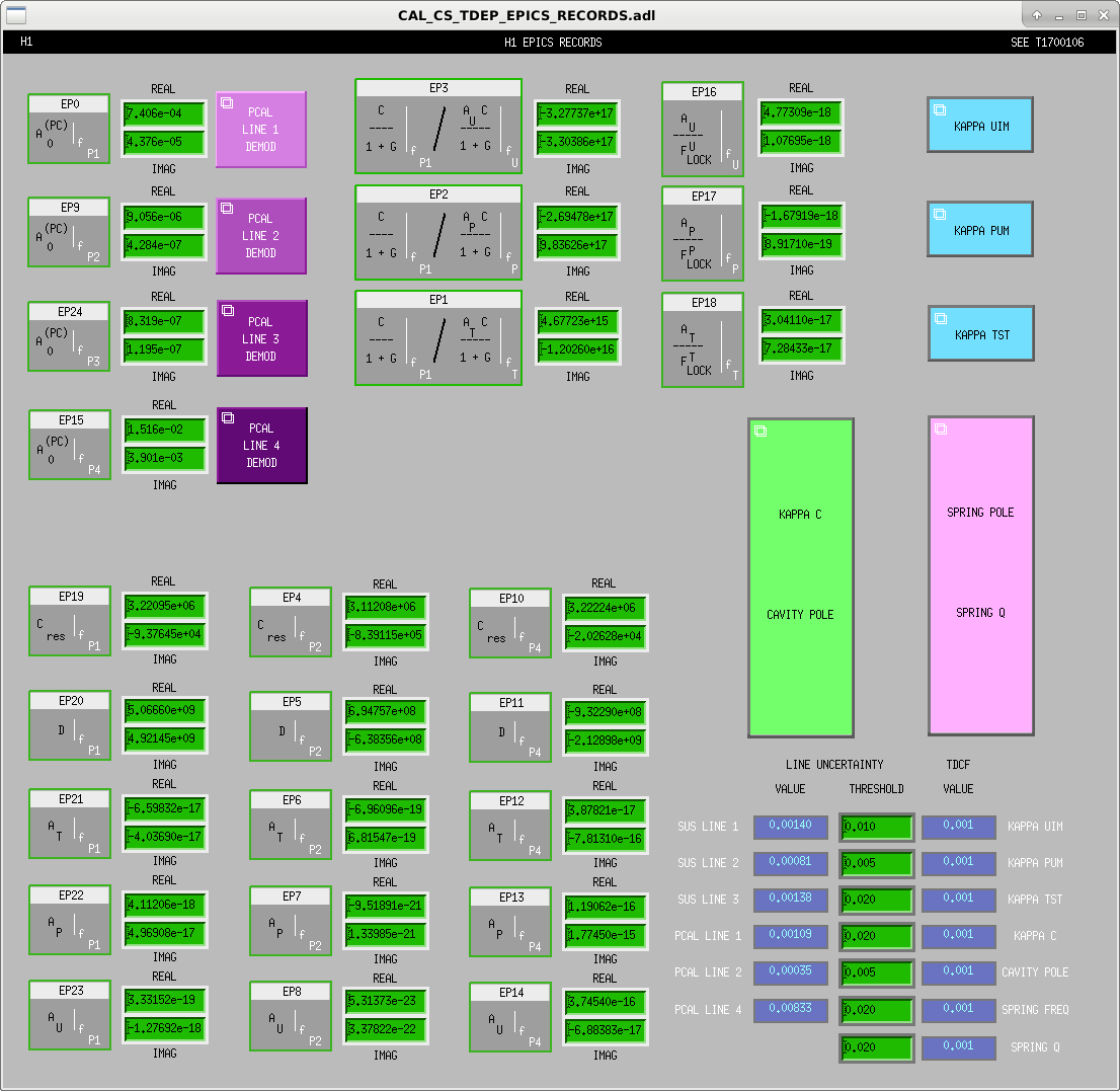
- EP12, EP13, EP14 (reference model values for each actuator stage at the 4th PCAL line frequency, i.e. the 7.93 Hz SRC detuning line) were incorrectly labeled in
/opt/rtcds/userapps/release/cal/common/medm/
CAL_CS_TDEP_EPICS_RECORDS.adl
- EP24 (correction to PCAL line transfer function at 1083 Hz 3rd PCAL line frequency) was missing in
/opt/rtcds/userapps/release/cal/common/medm/
CAL_CS_TDEP_EPICS_RECORDS.adl
All the above have been fixed and committed to the userapps repo.
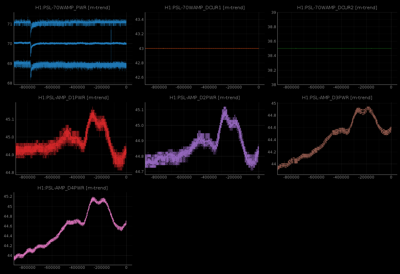
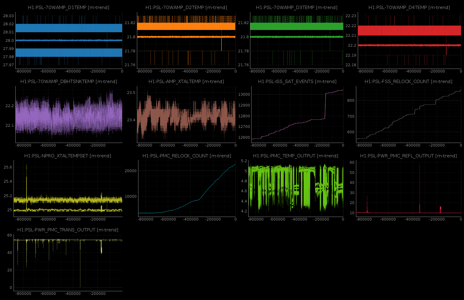
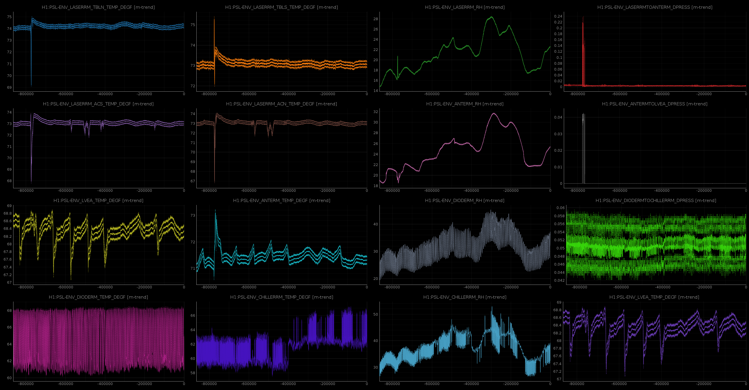
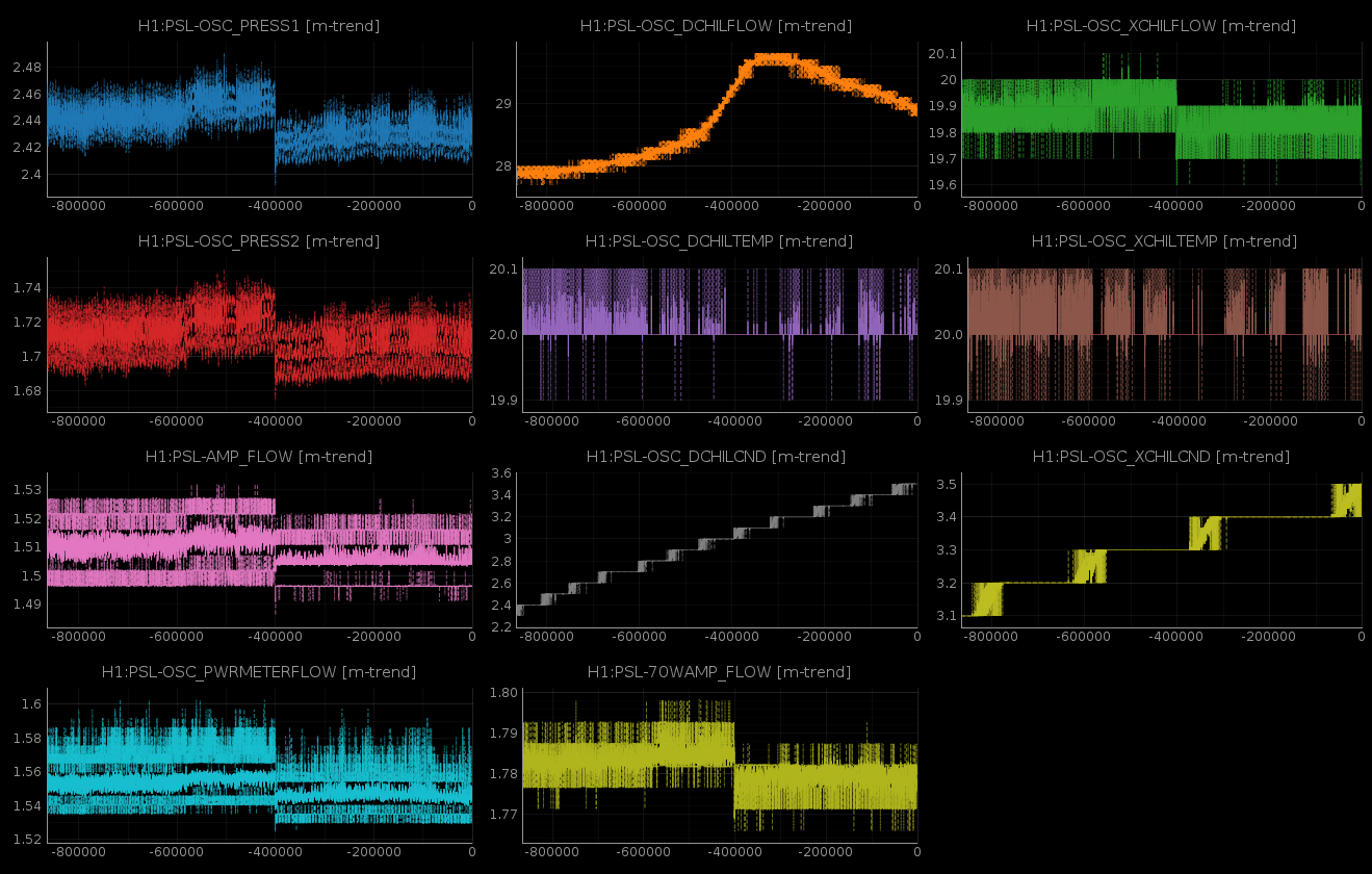
These trends leave a couple day of lapse. Given the recent "weather" of the laser, I don't feel the need to supplement these until the next set, next week.
My automatic reporting of an external EDCU channel change has hit a snag, resulting in an erroneous CFC flag on h1edc's STATE_WORD (attached).
There was some guardian work ongoing overnight from midnight to 5am. During this work, the guardian generated H1EDCU_GRD.ini file was being deleted and re-created (with the same content). This meant that at times my H1EPICS_GRD.ini creator was generating an empty file, which in turn resulted in GRD channels being removed from H1EDC.ini, and later returning them.
I'll work on a solution today.
TJ looked at the guardian code, it updates the H1EDCU_GRD.ini file as quickly as possible by staging a new file and replacing the contents in one atomic operation. So the mystery of what happened overnight deepens. I'm keeping the crontab running for now while we investigate.
Ops Shift Transition: 03/28/2019, Day Shift 15:00 – 23:00 (08:00 -16:00) - UTC (PT)
State of H1: Locking
Intent Bit: Commission
Weather: Partly cloudy. Winds are low. Temperatures are in the lower 40s to upper 50s.
Primary 0.03 – 0.1Hz: 0.01um/s
Secondary 0.1 – 0.3Hz: 0.1um/s
Outgoing Operator: Jeff
Quick Summary: IFO is locking smoothly after an initial alignment by Jeff
Craig Dan Danny Georgia + Jeff B and Ed
Over the past week we've taken a couple of steps with the ring heaters, trying to find a more optimal TCS configuration for 35 W input power. Craig and Dan previously set up the AWG_LINES guardian to inject frequency noise, intensity noise, and 9MHz RIN lines. I wrote a quick matlab script to demodulate these lines, and have made some plots of how these couplings change over time with the ring heater steps. This is building on an ipython notebook Dan had already written, but it cuts the data into chunks so it doesn't require the cluster to run. This work is ongoing but I'm posting what we've got so far.
It's a bit loose for now, but for interested TCS'ers, script lives here:
/ligo/home/georgia.mansell/TCS/AwgLineDemod/plotTCSDemodLines.m
On Monday Jenne decreased the ITM ring heaters in common by ~250 mW. She saw:
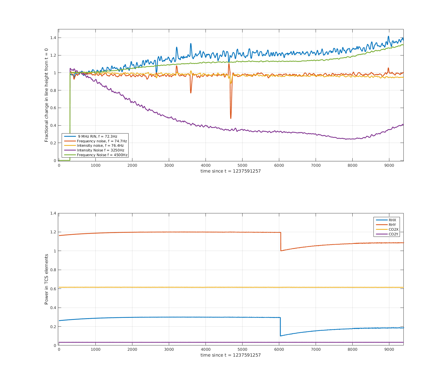
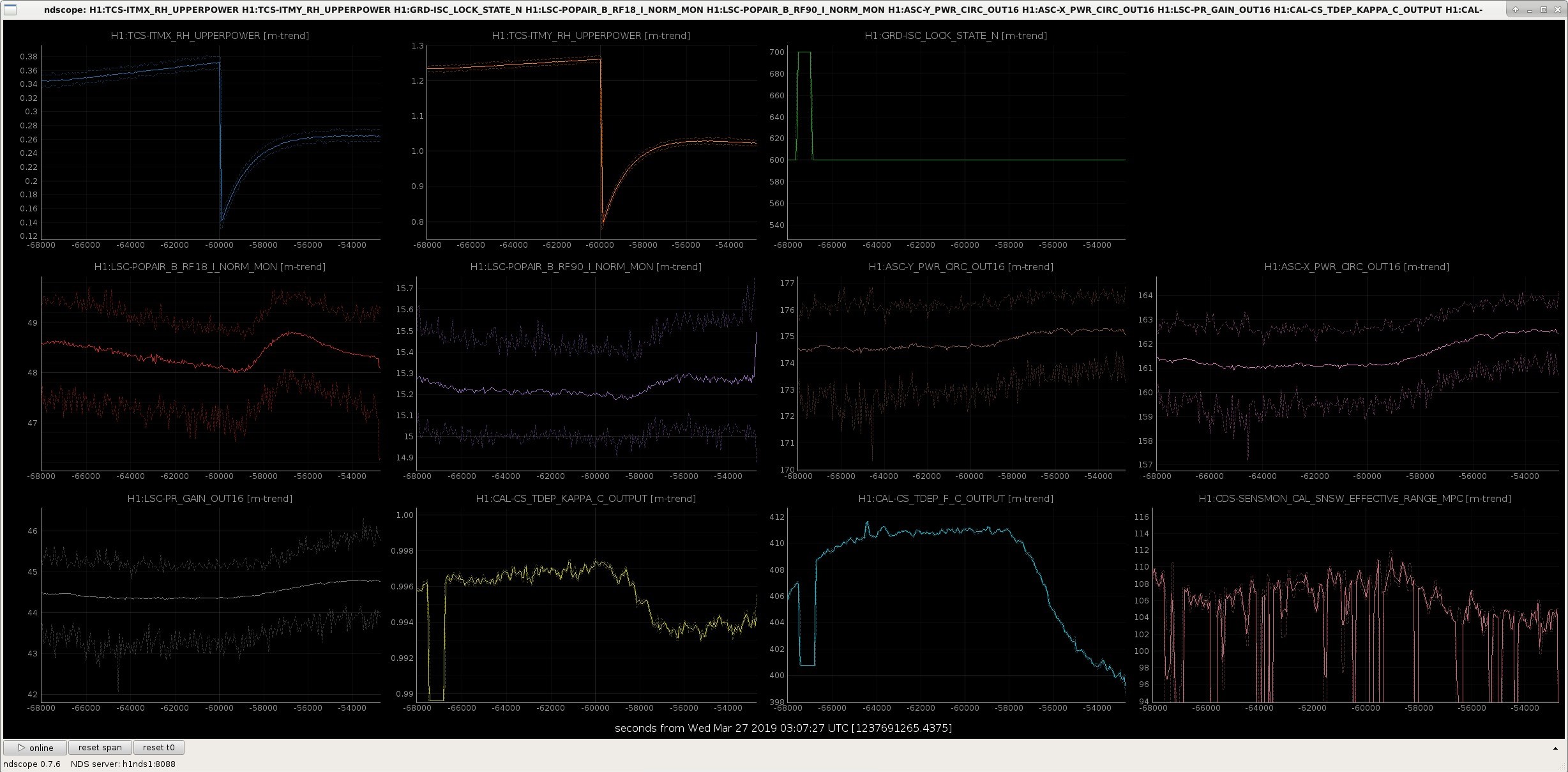
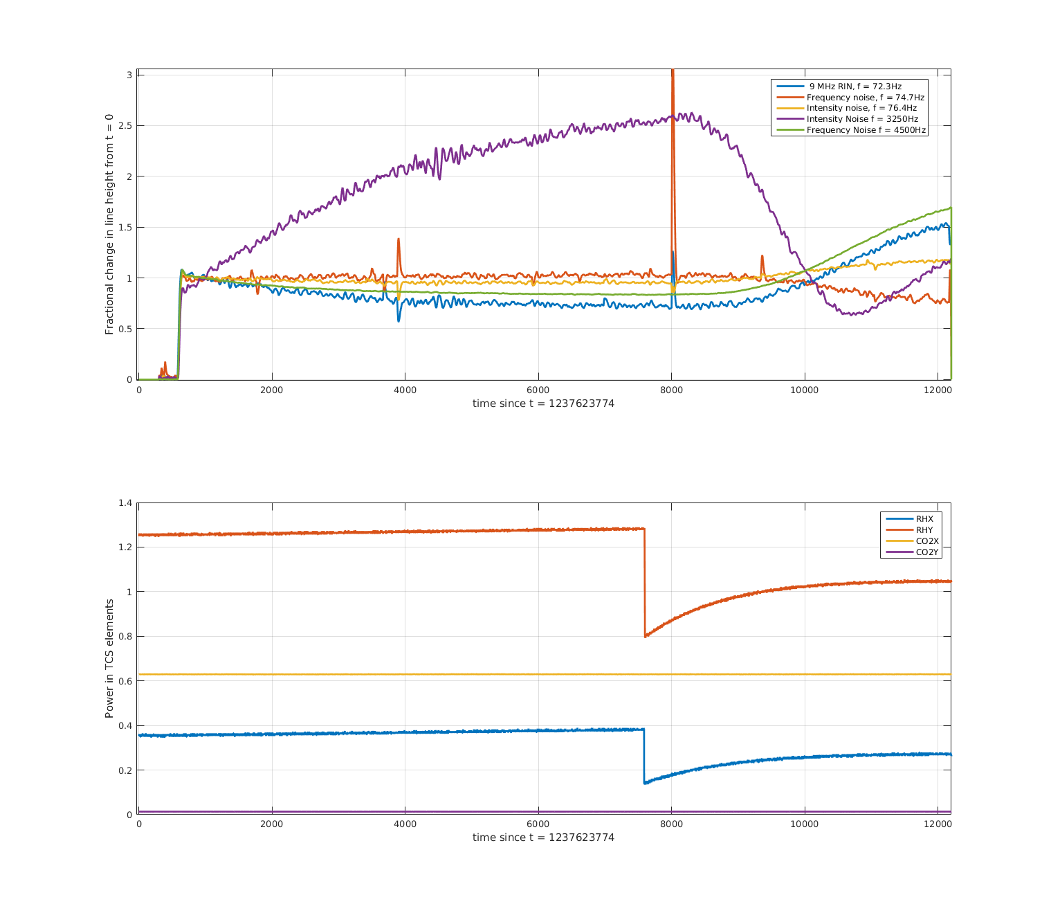
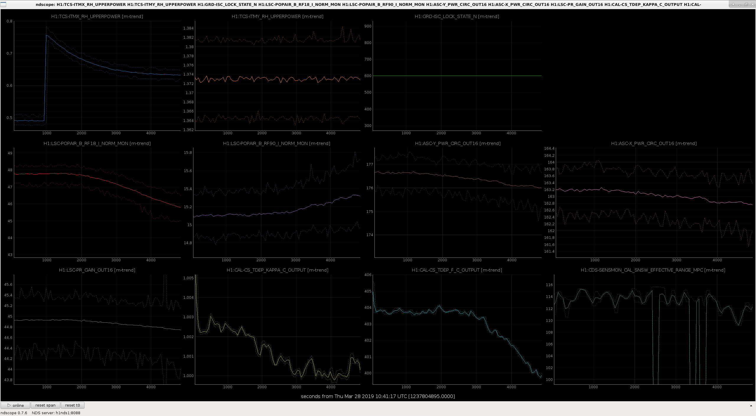
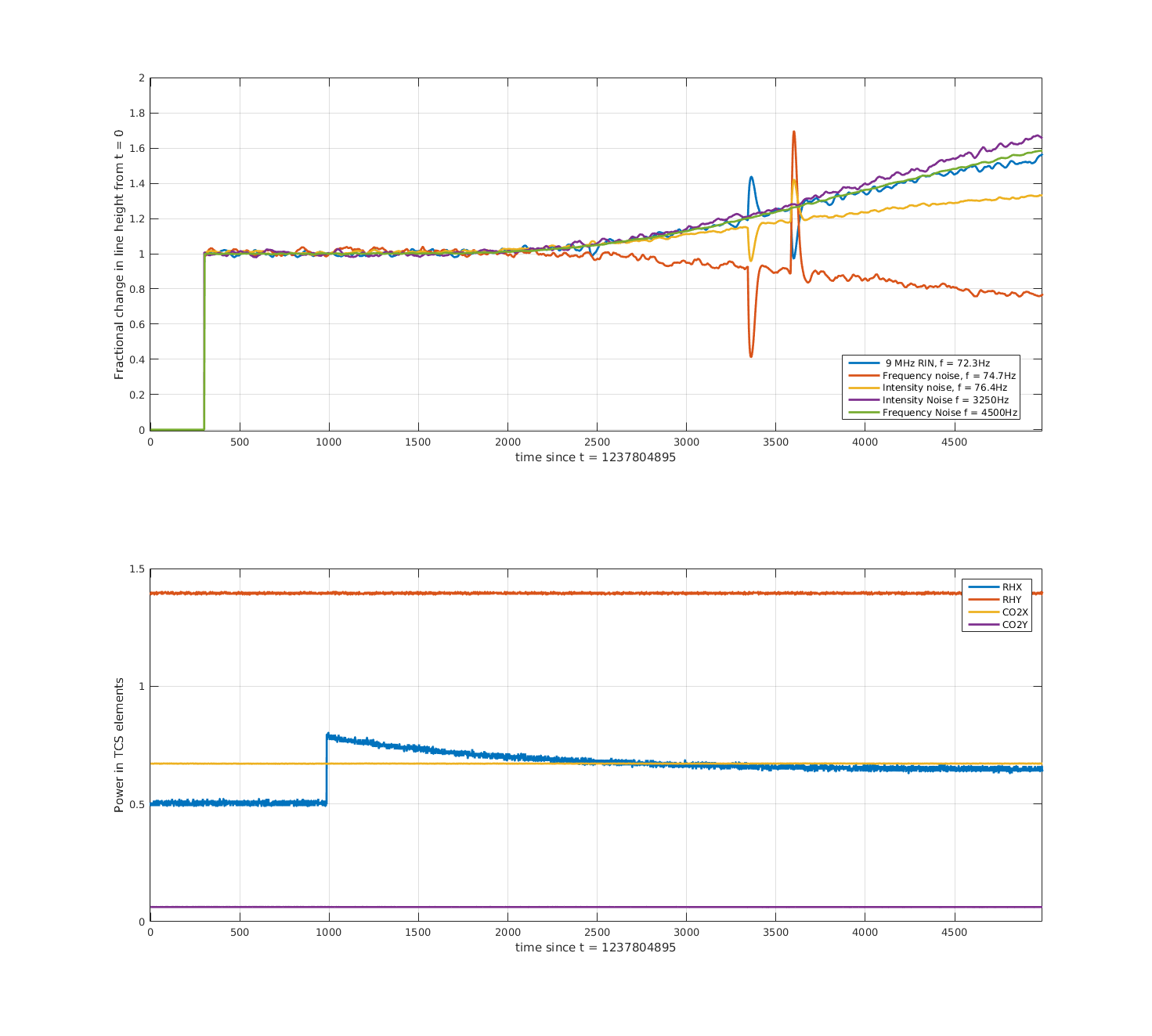
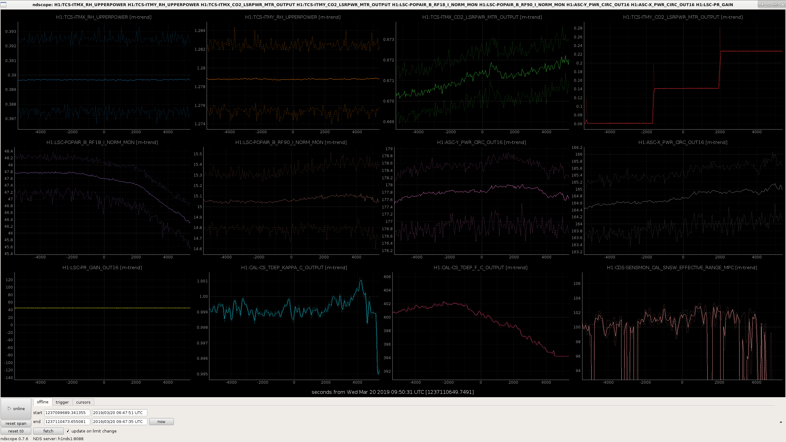
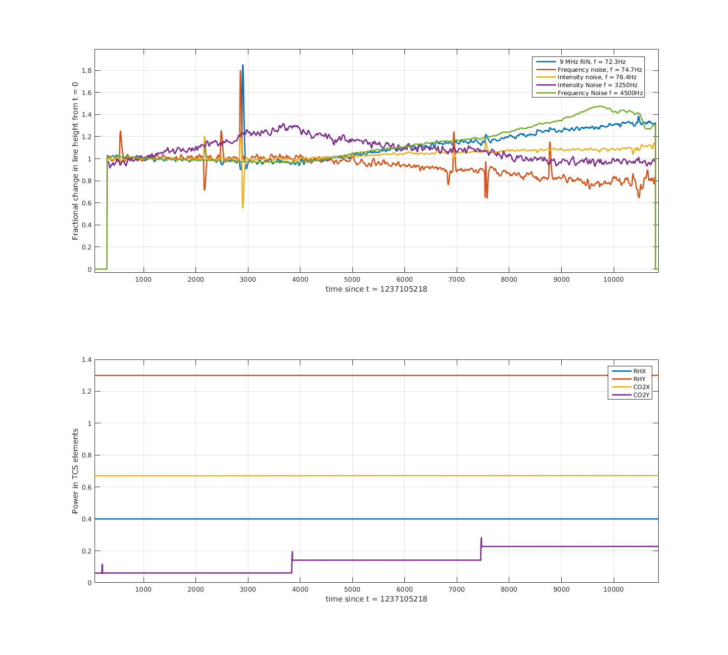
The first attachment shows an ndscope of the diagnostics, as well as the ring heater powers. The second attachment shows the demodulated lines, normalised to t ~ 700 s (sorry it's a bit dodgey for now). The time axis starts just after the first step down, at roughly the same time as the cursor in the first attachment (the lines were not on before this time), the lower plot shows the ring heater set_upper_power, which is controled by Danny's ring heater guardian.
The interferometer was well thermalised before this change, having been locked for 19 hours. Things to note: the coupling of the 9 MHz line, and high-frequency frequency noise appears to grow with this ring heater step. The high-frequency intensity noise coupling drops, though seems to turn back up towards the end - maybe we overshot some minimum coupling? The ring heater time constant is very slow. The frequency and intensity lines in the bucket seem unaffected.
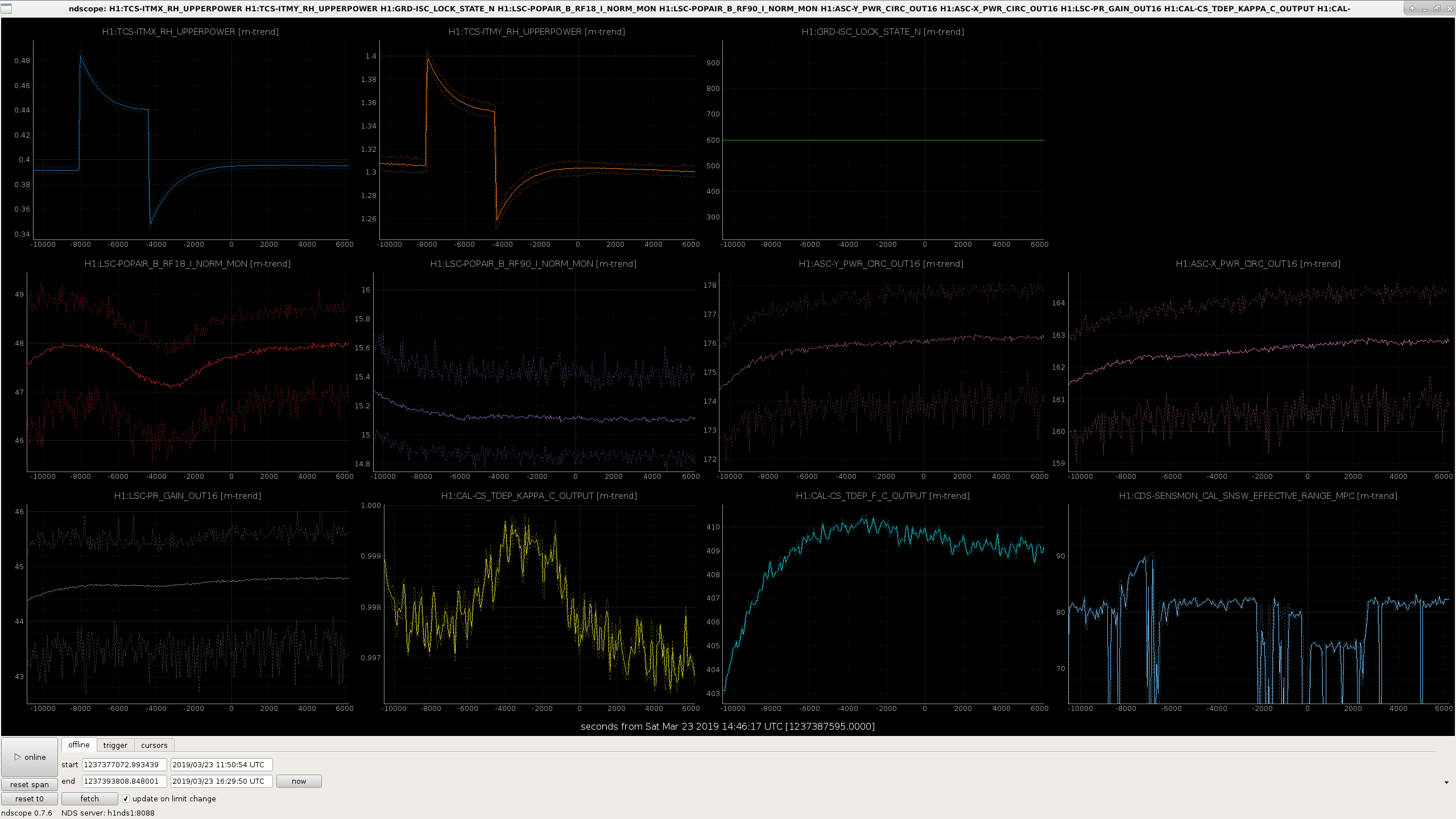
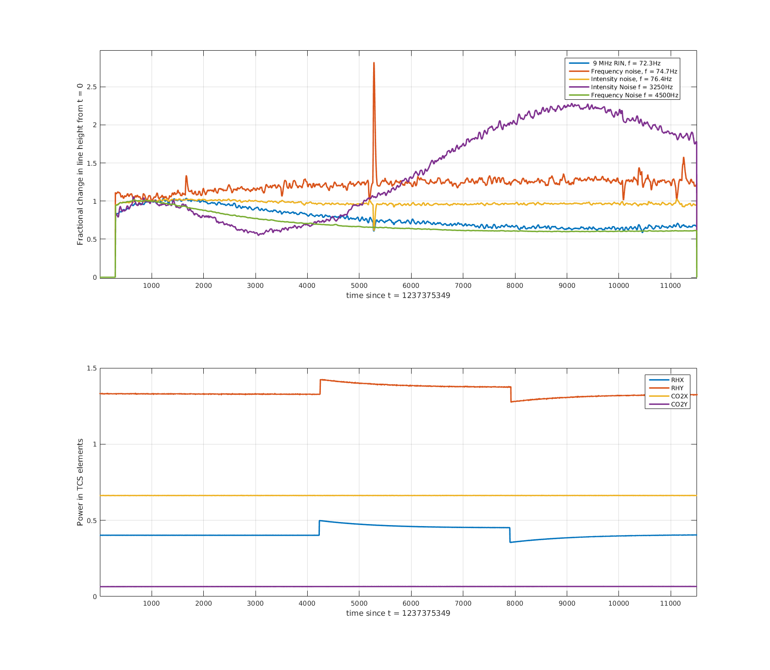
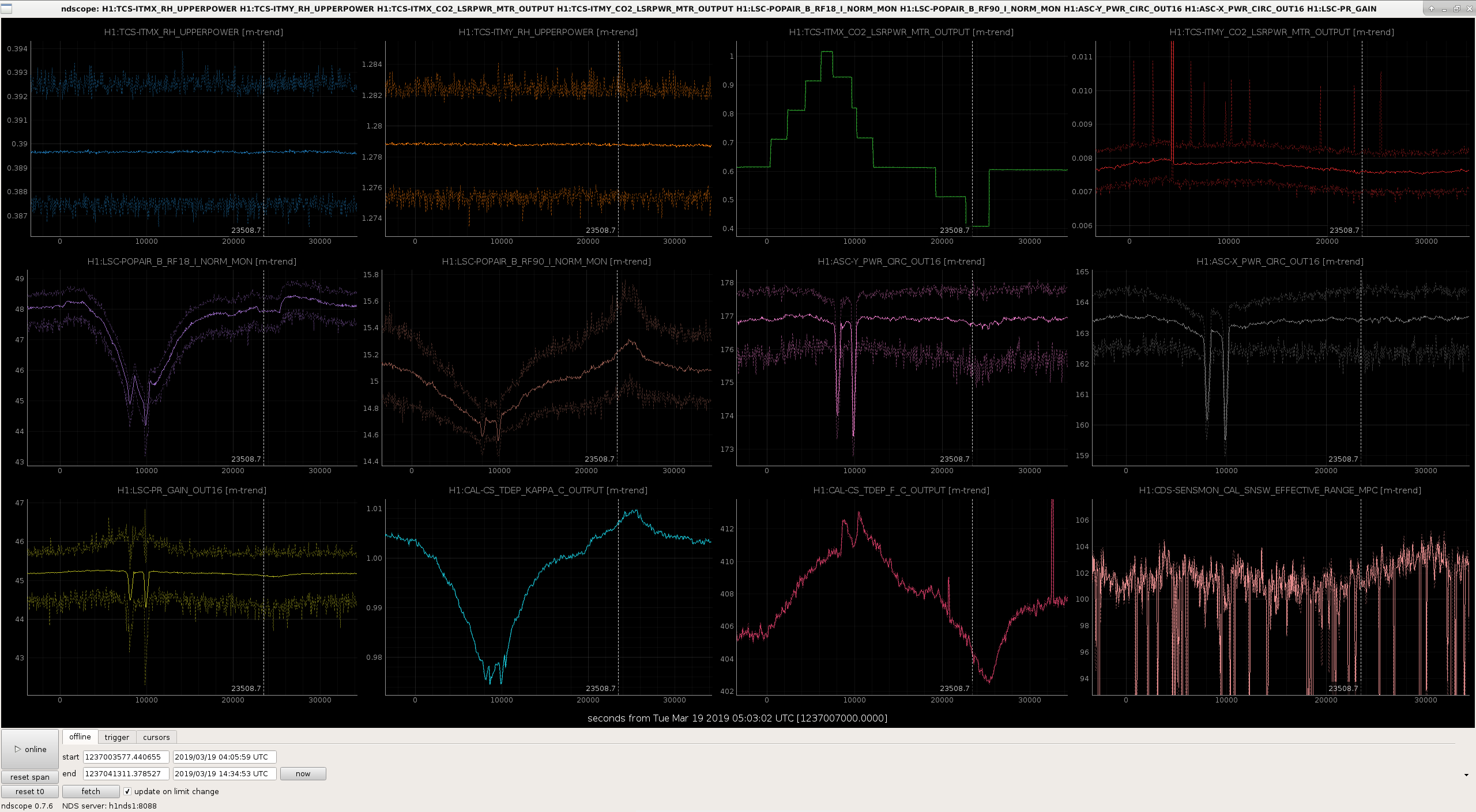
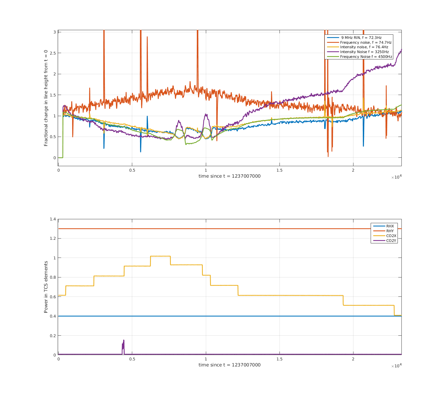
Later the same night, we tried a slightly differential step down in the ring heaters, lowering ITMX by ~0.1W and ITMY by ~0.26W. We see similar behaviour in our diagnostics (third attachment), increase in RF18 and circulating power, decrease in the f_c and range. Note that this step was taken sooner after locking, and that the interferometer was still thermalising. The fourth attachment shows the demodulated lines. Changes before the step at t~7500 are due to the thermalisation of the interferometer. After the ring heater step, the high frequency intensity noise again takes a dip (with a pretty fast time constant), while high-frequency frequency noise and RF9 increase. Craig noted that the high frequency line and the 9MHz RIN line (at 72.3 Hz) are moving together. With this step intensity noise in the bucket seems to rise, and frequency noise in the bucket seems improved.
On Friday night Danny and Ed took a 0.1 W common increase in the ring heater power. Note earlier that night we had seen that a 0.5 W increase on ITMY only caused POP_RF18 to plummet potentially causing a lockloss. During this step the interferometer was still thermalising, see for example RF90 (purple trace in fifth attachment) dropping before the ring heater step. I originally got excited to see the range increase but probably that was due to some squeezer shenanigans happening at the same time? With the increase in power RF18 looks like it drops a little, but other diagnostics don't show much. I think the demodulated lines (sixth attachment) are dominated by the thermalising IFO.
Tonight (@ 10:57:43 UTC) we have tried increasing the power on ITMX ring heater only, we requested 0.8 W from the filter input, where nominally it is 0.5 W. If future operators or commissioners would like to return this value to nominal after lockloss (eg if ASC is problematic), this can be done in the command line:
caput H1:TCS-ITMX_RH_INVERSE_FILTER_IN 0.5
The new custom mask has not been installed as far as I know. The testing, according to the mask guardian, has been done with the central mask.
The results from last night's RH_X step up by ~0.15W:
Overall, not good.
I've made the same plots of diagnostics and demodulated lines for some of the CO2 steps done last week by Dan and co.
Most of the analysis for this one was already done by Dan (alog 47658). First attachment shows the diagnostics, second attachment shows the demodulated lines. Some things to note
We did two tests around 20190320/21 with CO2Y power increasing, one with and one without the point absorber mask. The results were pretty similar. Third and fourth attachments are diagnostics and lines with the mask was one (the ifo had better thermalised for this test so the results are less confusing)
Based on all these test so far it's not obvious to me what combination of TCS settings we need to get the improvement we'd expect from out 30 - 35 W input power increase.
Was the second version of the CO2Y mask installed for this test? The first version is no longer valid due to the movement of the IFO beam.
Locked and Observing for most of the first half of the shift.
Jenne's IMC-VCO Sweep finished at 10:22 (03:22). Craig wanted to run some short injections and Violin ETM-X Mode-9 flagged as ringing up. Dropped out of Observing at 10:27 to run injections. At 10:38 took VIOLIN_DAMPING to DAMPING_ON_SIMPLE and set Mode-9 gain to -3. Could see damping engaging; at 10:40 went back to DAMPING_ON_DC.
NLN at 10:40. Had a few Violin Mode growing messages that bumped the IFO into Commissioning. Craig unmonitored these to clear SDF. Back in Observing at 10:45..
All OK and normal Observing.
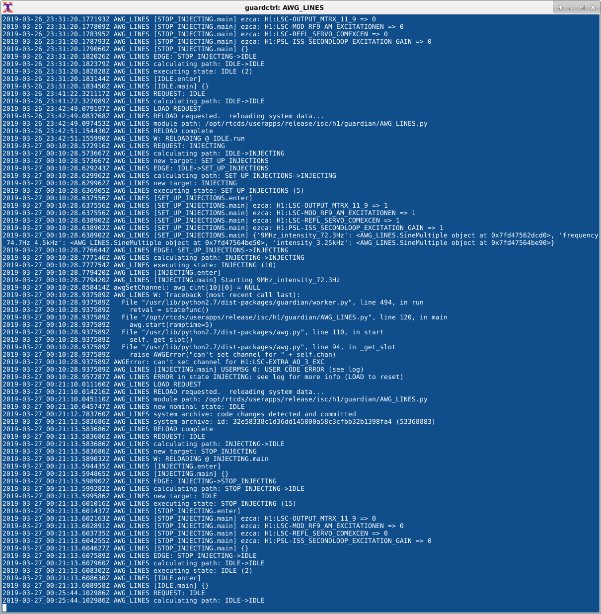
On Monday Jenne made the AWG_LINES guardian nominal state IDLE because the guardian was put into ERROR when the INJECTING state was requested and could not function correctly. The error was something to do with awg being unable to connect to excitation channels. None of the excitation channels were able to be connected to. Jenne's AWG_LINES error log attached. I tested this guardian again tonight since we needed the lines for an ITMX ring heater temperature increase (from 0.5 to 0.8 on the filter input). AWG_LINES seems to work as expected again, so I switched the nominal AWG_LINES state back to INJECTING and changed ISC_LOCK such that NOMINAL_LOW_NOISE puts AWG_LINES into INJECTING.
I made a python script that automatically runs PCALY broadband injections then DARM OLG measurements for the purpose of quickly measuring the DARM plant. This was used to measure the DARM plant several times overnight during a SR3 heater move to find that turning on the SR3 heater gives H1 a DARM prospring. Jeff K expressed interest in this script, so it now it lives in the cal SVN. To measure the DARM plant using this script, go to NLN_CAL_MEAS, open a terminal and run:python /ligo/svncommon/CalSVN/aligocalibration/trunk/Runs/O3/H1/Scripts/FullIFOSensingTFs/autoBroadband/PCAL_and_DARM_BB_injection_caller.pyBoth the PCAL and DARM injections take 83 seconds each. The subsequent MCMC fitting and plotting takes about two minutes. It will save data timeseries, ASDs, and TFs in/ligo/svncommon/CalSVN/aligocalibration/trunk/Runs/O3/H1/Measurements/FullIFOSensingTFs/autoBroadband/{date}/. Plots will be in/ligo/svncommon/CalSVN/aligocalibration/trunk/Runs/O3/H1/Results/FullIFOSensingTFs/autoBroadband/{date}/. Posted below are the three plots this script produces from a injection tonight at around 3:30am this morning (2019-03-28 10:30:28.000000 UTC): 1) The DARM plant with an MCMC fit 2) DARM OLG 3) CAL DELTAL / PCAL comparison As far as the DARM plant goes, the prospring frequency seems to have increased to about -5 Hz according to the fit. The fit is not great since the data is not great at frequencies before 10 Hz: it is difficult to drive hard enough with the PCAL to resolve the prospring. I have tuned a low frequency PCAL BB injection for future attempts at resolving the spring as well as the swept sine did earlier today. This is not yet a part of this script. We would like to try to move the SRCL offset and see if we can control the prospring frequency. This may have a direct impact on our range. This script will make a quick turnaround of the spring frequency possible.
TITLE: 03/27 Eve Shift: 23:00-07:00 UTC (16:00-00:00 PST), all times posted in UTC STATE of H1: Observing at 116Mpc INCOMING OPERATOR: Jeff LOG: 23:00 UTC Relocking 23:13 UTC Chandra to mid Y 23:28 UTC Restarted video0 23:29 UTC Restarted video3 23:45 UTC Started adjusting ALS fiber polarization 23:59 UTC Chandra and Kyle done running scroll pump at mid Y (alog 47944) 00:02 UTC Done adjusting ALS fiber polarization. Could not get the X arm ALS fiber polarization error less than 15%. It is odd that it could go to greater than 100%. 00:34 UTC Jeff K. discovered that the ETMX L2 LEN to YAW filters had a gain of +1, should have been -1. Explains previous two locklosses from LOWNOISE_ESD_ETMX. Jeff K. fixed. 01:03 UTC NLN. Accepted SDF differences from adjusting ALS fiber polarization. (alog 47947) 01:09 UTC Set observatory mode to calibration. 01:22 UTC Lock loss. 4.2 Hz ASC oscillation. (alog 47949) 01:30 UTC Starting initial alignment 01:54 UTC ITMY camera has died 01:56 UTC Powercycled h1digivideo2. Everything back except h1cam23. 02:04 UTC Realized I forgot to set observatory mode to aligning. Did so. 02:42 UTC Initial alignment done. Had to intervene for SRM. 03:24 UTC NLN 04:07 UTC Observing (alog 47957) 05:03 UTC Dropped out of observing by TCS ITMY CO2 guardian. Seemed to recover itself. Went back to observing. 06:16 UTC Started Jenne's IMC VCO sweep script (alog 47954) 06:24 UTC Reloaded INJ_TRANS guardian per Adam's request (alog 47942, 47943)
As suggested by alog 47939, I've written a script that will slowly sweep the IMC VCO while we're in Observe. Patrick has instructions on how to run it, and he (or the Owl operator) will alog the times that the sweep has run.
06:16 UTC Started script as controls on zotws3.
The VCO Sweep ended on 03/28/2019 at 10:22:05.349809 (UTC), 03:22:05.349809 (PT).
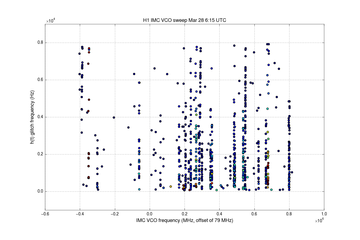
Here's a quick analysis, we'll do a more thorough one later. The attached plot shows glitches in DARM as a function of VCO frequency. There are many different lines that give beatnotes. The widest clean area is around 78.8 Mhz, with 79.75 MHz second best. It would be best to spend another hour doing more restricted sweeps over any proposed areas we plan to use. If the calibration from the VCO tuning offset to the frequency is needed, Detchar can fit this data and provide that. (Edit: New plot uploaded without the axis labels cut of.)
Exact sweep times for the ramp from +5V to -5V:
Plot 1 shows Frequency against tune voltage. The VCO frequency is offset by 79.2 MHz.
Plot 2 shows a histogram of the VCO frequencies during ramping in 5 kHz bins. Looks like we covered the full range.
The VCO frequency can be estimated by VCO frequency = 79.2 MHz – 44 kHz + v 140.3 kHz – v3 0.4447 kHz, with v the tune voltage.
For 78.8 MHz we get –2.59 V, and for 79.75 MHz we get +4.53 V. The full range of this VCO is from 77.9 MHz to 80.4 MHz. With the full tune voltage range of ±10 V, we can access frequencies from ~78.0 MHz to ~80.3 MHz.
A series of DetChar safety injections is scheduled to go into LHO at 05:00:00 PDT tomorrow morning (28 March 2018). The injection file starts at 05:00:00 PDT, lasts for 91 seconds, and the first actual injection should go in at 05:00:10 PDT.
The schedule file and waveforms have been uploaded to the h1hwinj1 machine and I asked Gary (at LLO) to ask Patrick to reload the INJ TRANS guardian.
Reload completed.
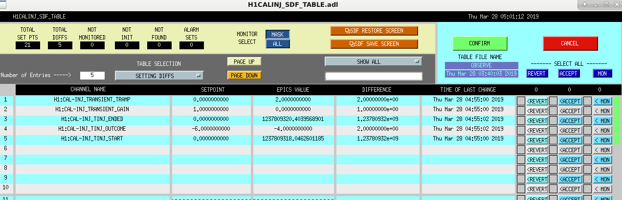
At 11:55 (04:55) IFO dropped out of Observing due to SDF Difss with CALINJ SDF Diffs. At 12:01 (05:01) Accepted SDF Diffs and put IFO back into Observing Mode. It may be unrelated but lostlock at 12:04 (05:04).
It would be better to un-monitor these channels in the SDF as they change when we carry out hardware injections. The injections should have finished at 5:01:30 PDT, which doesn't quite match up with the lockloss at 5:04.
These injections do not appear to have been successful in as much as H1:DMT-INJECTION_DETCHAR:1 was not active during any of the injection times. We're re-scheduling these for the morning of Fri March 29, 2019.
To un-monitor the channels open the SDF screen for CAL-INJ (while in Observe), set the "TABLE SELECTION" to "FULL TABLE", set "MONITOR SELECT" to "ALL" (this part may not me necessary). Channels with the final green tab lit up are currently being monitored. To un-monitor a channel click on the "MON" tab and hit the "CONFIRM" button. A list of the channels that we want the monitoring removed are shown in this screenshot (the ones with the yellow box in front of MON).