Ops Shift Transition: 03/26/2019, Day Shift 15:00 – 23:00 (08:00 -16:00) - UTC (PT)
State of H1: Maintenance
Intent Bit: Commissioning
Weather: Wind is ranging between 0-10 mph. Temperatures are in the upper 40s to lower 50s
Primary 0.03 – 0.1Hz: X & Y axis is at 0.06um/s and Z axis is 0.9um/s
Secondary 0.1 – 0.3Hz: 0.5mu/s
Outgoing Operator: Jeff
Summary: Beginning Tuesday Maintenance
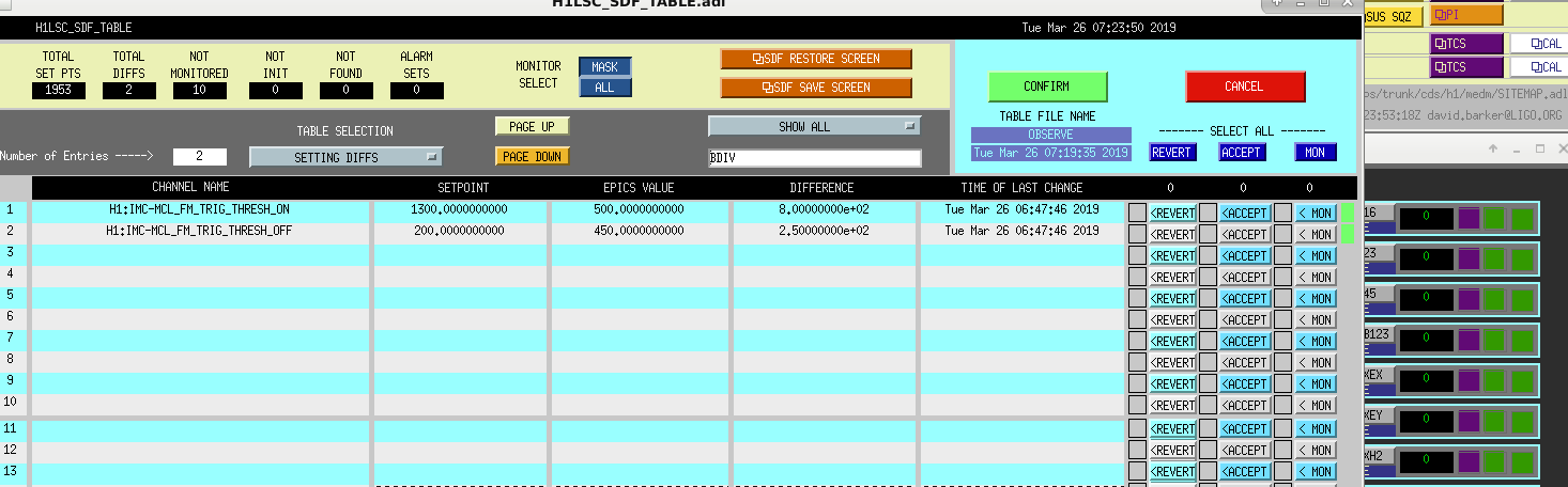
This morning going back into Observe I accepted two SDF Diffs for IMC-MCLFM_TRIG_THRESH_ON and _OFF. Values are captured in the attached screen shot.
IFO has been locked at NLN for the past 2.5 hours. With 35.2w the range is 110.3Mpc. There have been a few glitches, but not too bad. The wind has laid down to no more than a Light Breeze and wind seismic has followed suit. The ITM-Y violin mode-12 keeps popping up as growing. It seem to be bouncing around between something like 1.15 and 1.22. Will keep an eye on it. Commissioners have left for the morning.
Following on from Jenne's common ring heater change (lowering power), we are taking a differential ring heater step tonight. We will reduce ITMY to the same power as Jenne did, and take a smaller step on ITMX. If there are problems with ASC while reacquiring lock, these changes might need to be reverted.
| ITMX RH Filter input [W] | ITMY RH filter input [W] | |
| Nominal | 0.5 | 1.4 |
| Common step today | 0 | 0.9 |
| Differential step tonight | 0.25 | 0.9 |
( - I'm quoting filter input requested power here, there's an offset from the actual ring heater set power I'm not sure about.)
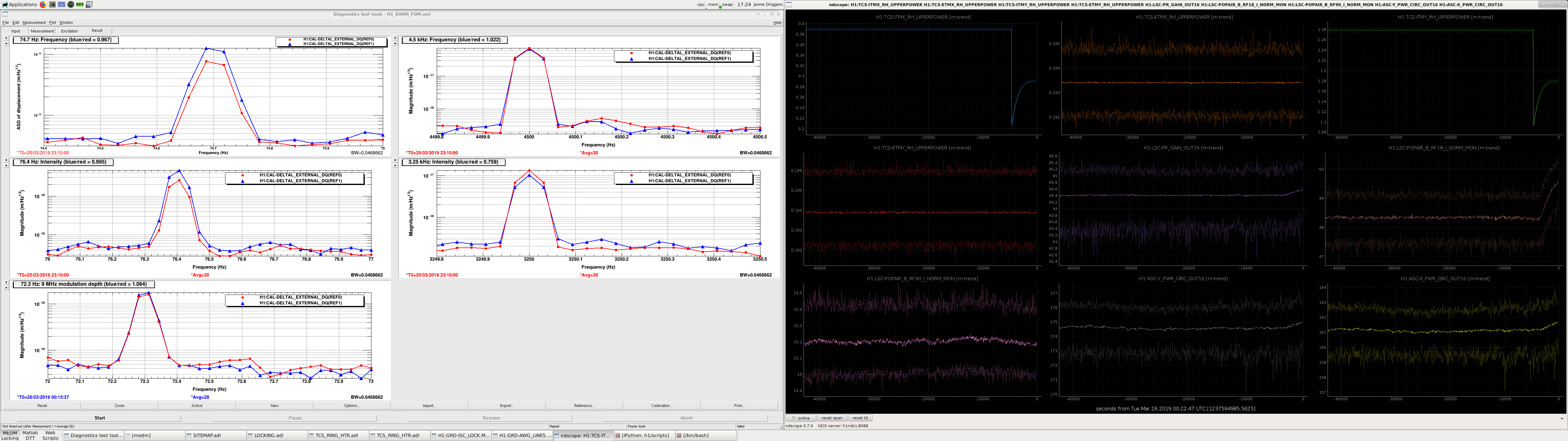
Craig has coded up a live monitor of the frequency and intensity noise lines which I'm running on ZOTWS22. The realtime monitors are found here:
/ligo/home/craig.cahillane/monitors/AWG_Line_Monitors.py
To run them you might need to use craig's environment, by running:
source /opt/rtcds/userapps/release/cds/h1/scripts/setup_anaconda
source activate cragenv
(edit: original title to alog quoted wrong start time timezone for measurement)
After ASC lockloss reset the Ring Heaters back to original values. RH Filter Input for ITM-X is now 0.5w, RH Filter Input for ITM-Y is now 1.4w.
Just to clarify: the nominal ring heater values I quoted in this alog are 0.1 W higher than the actual nominal ring heater vales: I got confused by the slow response of the filtered output.
Before yesterday, ITMX_RH_INVERSE_FILTER_IN was 0.4 W, and ITMY_RH_INVERSE_FILTER_IN was 1.3 W.
Craig, Georgia, Jeff B, Patrick
We accidentally lost the 24 hour lock during an excitation (1237609866). Patrick did an initial alignment, and we reacquired lock with the ring heater settings as Jenne had left them (0.1 W on ITMX and 1 W on ITMY). I thought that the AS_AIR camera looked a bit funky, but maybe it's always like that? See first attachment for a screenshot taken at the LOWNOISE_COIL_DRIVERS state. We made it to NLN and hung out for 3 mins before losing lock to a fast-ring-up 0.48Hz oscillation in ASC pitch loops (1237616294) see second attachment for ASC control signals. Based on the oplevs it seems that CSOFT was the issue.
Given the link between ASC and TCS, Craig lowered the ring heaters back to their nominal values (0.4 W on ITMX and 1.3 W on ITMY). Note that there seems to be a 0.1 W offset between the inverse_filter_in and the final power the ring heater actually gets set to, (edit: there's nothing wrong with the filter, I was just too impatient with the ring heaters) so we've requested powers 0.1 W above what is written above. We reached NLN again and lost lock after 5 mins again due to the ASC pitch ring up (1237618224), possibly because the thermal state of the IFO was still settling.
In the next lock we chilled out at POWER_30W, and found the 0.48 Hz oscillation ringing threateningly. I increased the CSOFT_P gain and this seemed to help. It turned out this gain was going to be turned up in LOWNOISE_ASC anyway. We went to NLN and have been locked fine, and observing, since then.
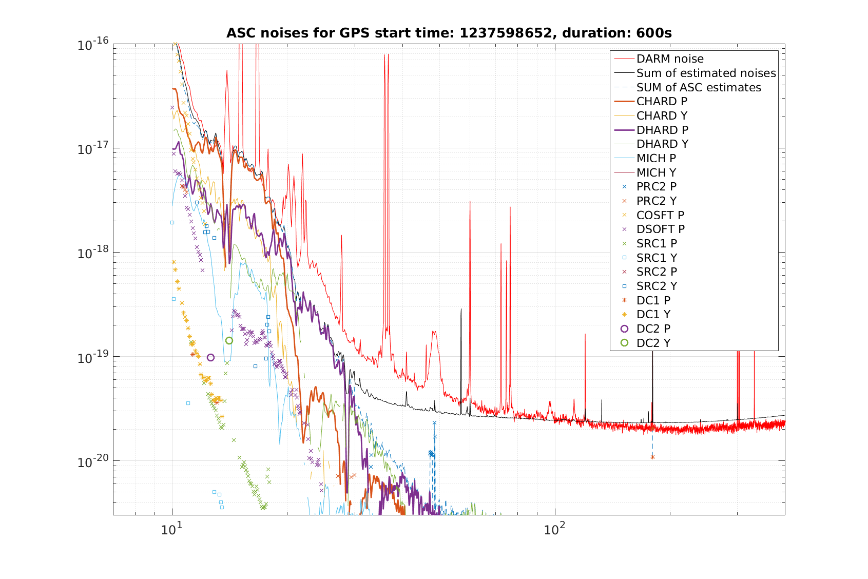
I re-ran the noise budget injections for CHARD_P, CHARD_Y, and added templates for DC2_P DC2_Y, after Jenne noted excess coherence between DC2_Y and DARM last week. The third attachment is the ASC noise budget as of today. The DC2 centering loop did not show elevated coherence with darm even with an excitation a couple of orders of magnitude above ambient, but there is still ~0.2 coherence around 23 Hz without an excitaiton, I'm not sure what is going on there. Meanwhile, CHARD_P is limiting us between 10 and 20 Hz, not too surprising as its cutoff was relaxed last week. Final attachment is the full noise budget.
TITLE: 03/25 Eve Shift: 23:00-07:00 UTC (16:00-00:00 PST), all times posted in UTC STATE of H1: Lock Acquisition INCOMING OPERATOR: Jeff SHIFT SUMMARY: Jenne made ring heater setpoint changes. Nutsinee, Georgia, and Craig ran measurements. Currently locking to NLN, then losing lock. Ran initial alignment after first lock loss. Georgia and Craig are still here. Getting LSC Servo Board Split Voltage is High errors before lock loss. LOG: 23:04 - 23:19 UTC Change to commissioning for Jenne to make ITM ring heater change 02:26 UTC Craig starting measurement. Out of observing. 02:31 UTC Nutsinee loaded changes in SQZ guardian. Ran into error. 02:34 - 02:41 UTC Craig to PSL racks. Plugging in SR785. 03:41 UTC Nutsinee starting measurements 03:49 UTC Georgia running measurements 04:30 UTC Lock loss Running initial alignment Lost IMC in MICH_DARK_LOCKED. Georgia lowered the input power. I cleared WFS histories. 06:15 UTC Back to NLN 06:17 UTC Lock loss 06:46 UTC Back to NLN 06:50 UTC Lock loss
Craig, Georgia, Nutsinee
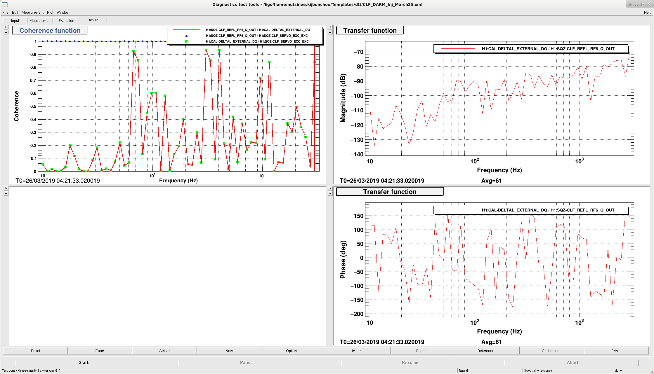
It seems like we have non-linear coupling from CLF to DARM. The coherence plot wasn't very obvious but we clearly saw out injection showed up everywhere in DARM as we swept. Lockloss before we could inject more squeezing measurement (it's not the squeezer!).
Hmm. How hard were you driving? I suppose it's either fringe-wrapping or nonlinear upconversion of the backscatter. At LLO, driving the ZM's also shows such nonlinear conversion into DARM LLO43807
The relevant ZM1 drive plot in DARM.(DARM calibration not setup here, but you can clearly see the 2F and even 3F harmonics for a small 1F drive)
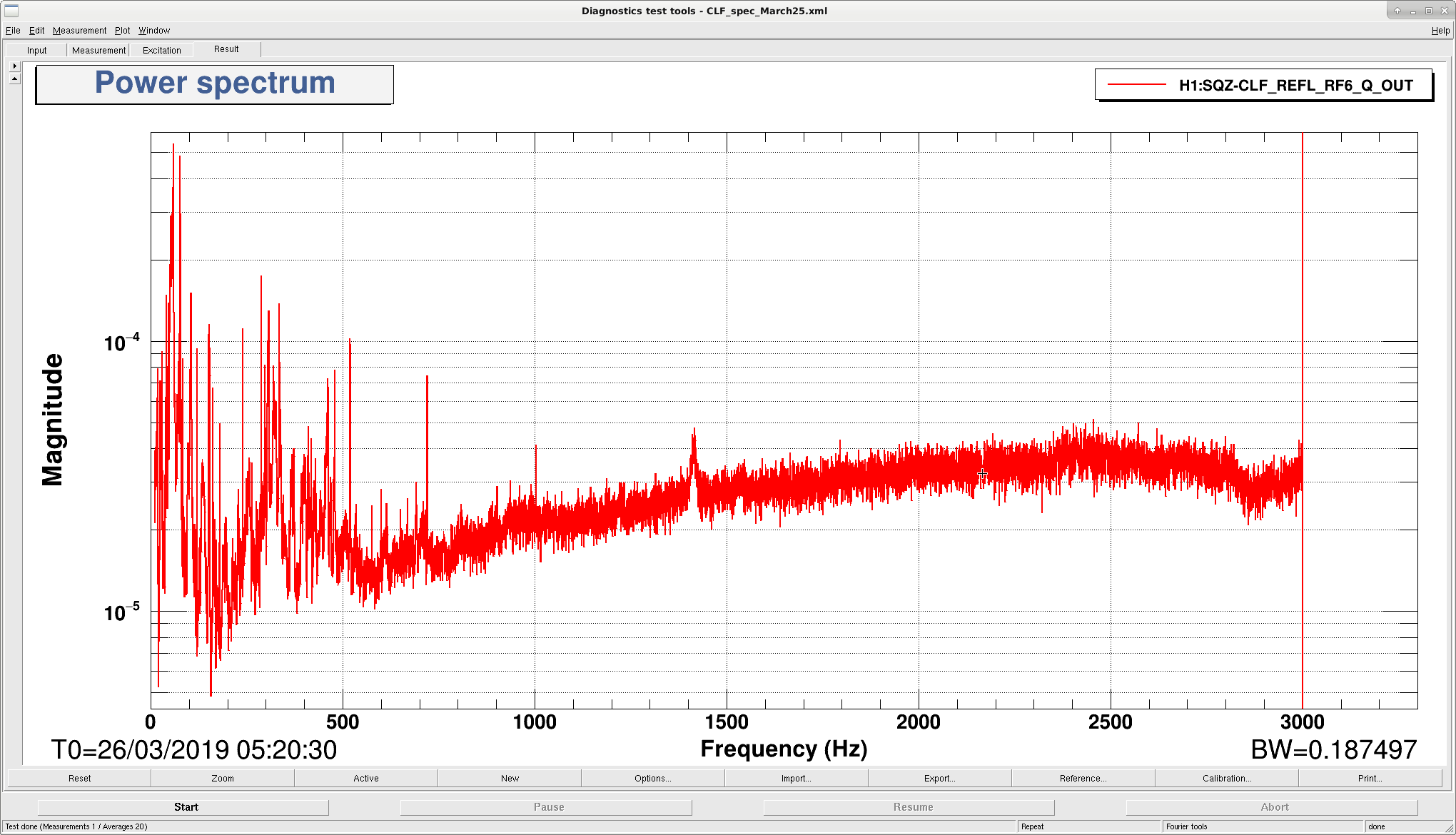
I assume we are modulating the back scattered light, so the phase wanders around. We will have to repeat this with a power spectrum peak height ratio measurement.
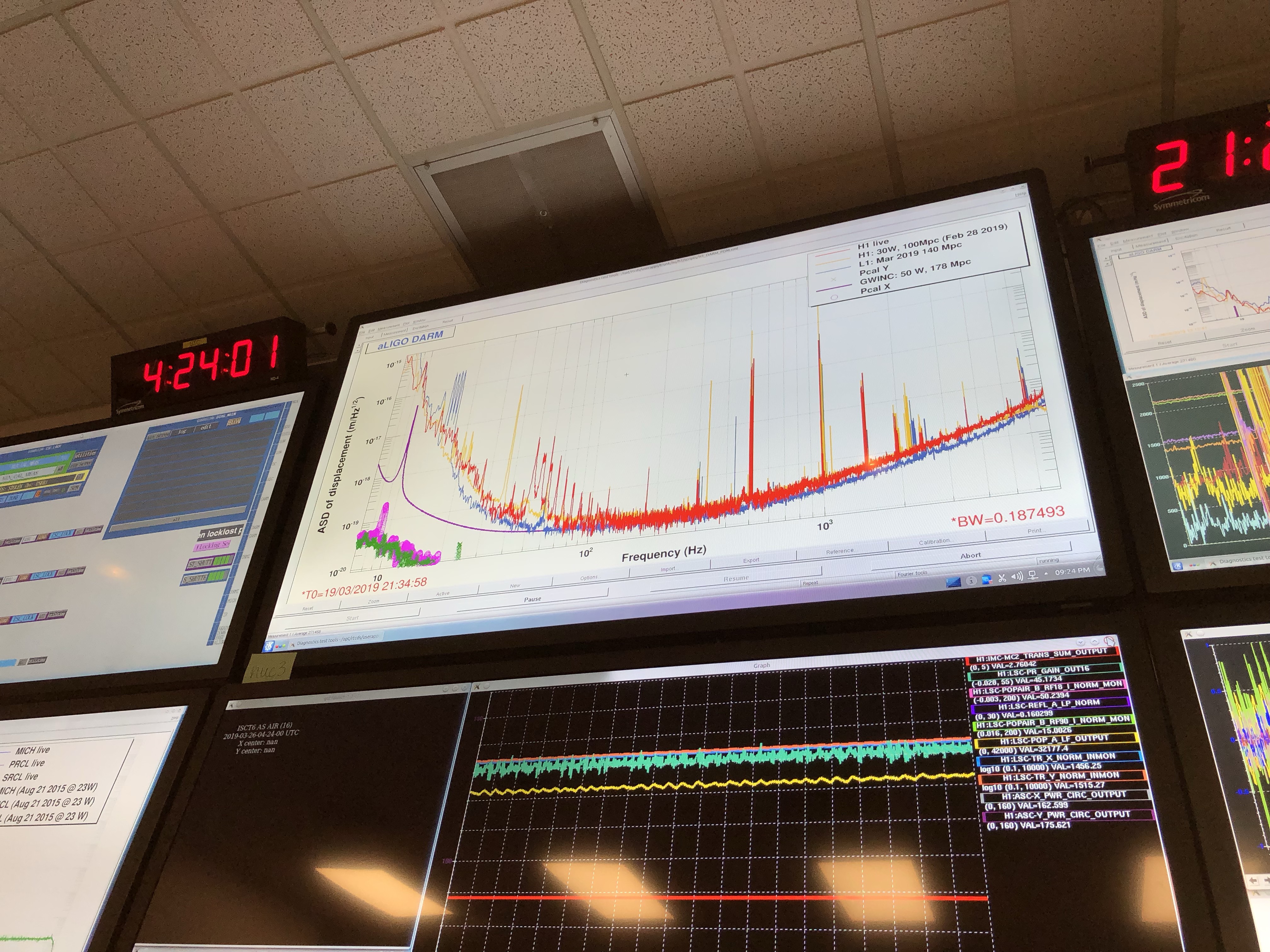
Jenne stepped down the ITM ring heaters in common today, and Keita okayed some commissioning time, so I checked on the DARM plant. We are still running with pro-spring detuning. From the measurement the MCMC gave the following fit: Gain = 3.15e+06 cts/m Pole = 428 Hz Delay = 5.64e-05 s Spring Freq = -3.03 Hz Q = 349 This is an apparent reduction in the DARM optical gain as reported on March 20th. From March 20th, The DARM optical gain goes down, the DARM pole increased, the spring frequency went from -4 Hz to -3 Hz. The only thing about the DARM plant which has changed is the ITM ring heaters temps going down, as far as I know.
Have remained locked. Jenne has made ITM ring heater setpoint changes. Craig has recently started measurements for which we are currently out of observing.
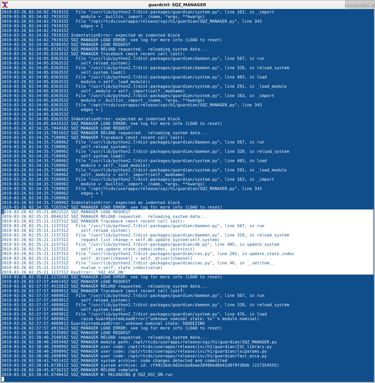
Looks like TJ changed the state name to be more consistent with LLO (SQUEEZE and NO_SQUEEZE) but it resulted in load error (see attachment). I reverted it for now.
A small change I made -- PREP state is now looking at TTFSS status and will prompt users if TTFSS is not locked.
Apologies, I mistakenly edited this instead of my copied file.
After seeing that stepping the ITM ring heaters up in common didn't make improvements to the IFO (alog 47851), I have made a step down in common. This means that we have to be watchful for any ITM violin modes to go bonkers, but so far (3000 sec after the step) things still seem okay for now.
Just before doing anything, Patrick took the IFO out of Observing for me, so that we can easily flag that this is when the change happened.
I followed the instructions in Danny's alog 47770, although the ITM ring heater guardians were already in the FILTER_RH_INPUT state, presumably because they needed to be there for a few days after the Saturday night test. I changed H1:TCS-ITMY_RH_INVERSE_FILTER_IN from 1.3 W to 1.1 W, and I changed H1:TCS-ITMX_RH_INVERSE_FILTER_IN from 0.4 W to 0.2 W. I think I'm a little confused as to what those really mean, since the requested and measured power for each segment on ITMY is going to about 1.2 W, not 1.1 W, and the requested and measured power for each segment on ITMX is going to about 0.3 W not 0.2 W. But, it's still a step down in power, roughly in common, so the step will still show us if this is the direction we want to go.
As soon as I had made the ring heater change, I remembered to turn on the AWG_LINES guardian injections for intensity, frequency, and 9 MHz RFAM. So, I won't have peak heights to compare to from before any changes happened, but the lines are at least going now, and we can see how they change from the start of the step to the end of the step, and back to nominal (if I go back to nominal). I requested the AWG_LINES guardian by hand to go to INJECTING, but later realized that I could have just done it with the ISC_LOCK guardian.
To then get the IFO back to Observing, I accepted the SDF diffs for LSC, PSLISS and one of the Beckhoff modules to let the excitations for my injections go through. I also had to uncomment the line in ISC_LOCK, so that it would think that the AWG_LINES guardian should be in the injecting state, not the idle state, so that the ISC_LOCK node would be happy with its subordinate. I also (while in the IDLE state of AWG_LINES, after having manual-ed there from INJECTING) changed the nominal of that guardian to be INJECTING, so that it would report OK, so that ISC_LOCK would report OK, so that we could go to Observe.
After these minor guardian shenanigans, and the SDF accepts, I put the IFO back into Observing. (Sorry Patrick - I should have let you know I was done and let you do any checks necesssary)
After ~75 minutes, the circulating powers are increasing (a very small amount), but the frequency and intensity noise coupling at 75 Hz are getting worse. In the spectra, red is the original hotter, and blue is the current cooler state.
Violin modes all seem okay for now.
Just made another step, setting ITMX filter input to 0 W, and ITMY filter input to 0.9 W. Both of these are -0.4 W from where they started earlier today.
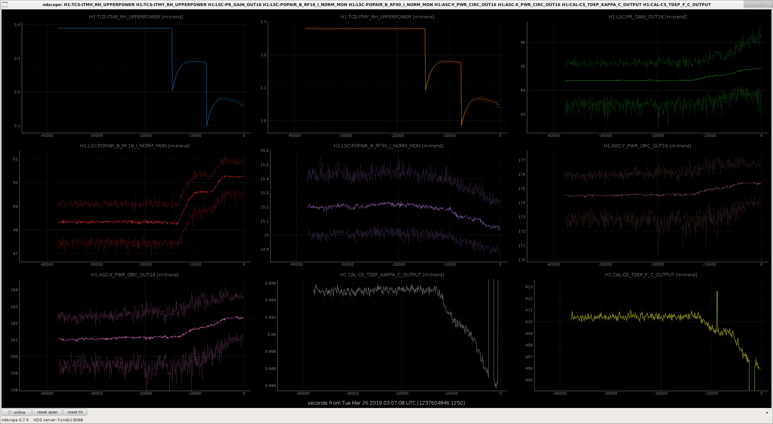
The IFO is pretty much thermalized from the second ring heater step I took today. The arm circulating powers are going up, and they are getting closer to eachother - the Xarm power is increasing slightly faster than the Yarm power.
The frequency and intensity noise couplings in the bucket are certainly worse - we likely need to do some differential tuning next. PRCL coherence is much higher now than it was earlier, suggesting (as was a suspicion) that it is mostly just reporting frequency noise, not direct PRCL noise. The MICH and SRCL feedforward look like they could use some tuning, but that's not really going to be a good use of time until we've done a bit of differential tuning.
Georgia is going to keep stepping TCS gently around tonight, and is getting the script ready to look at the injected lines.
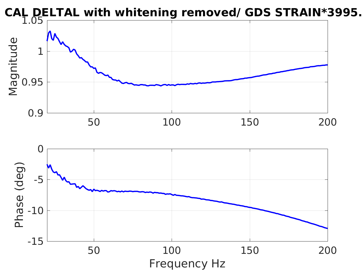
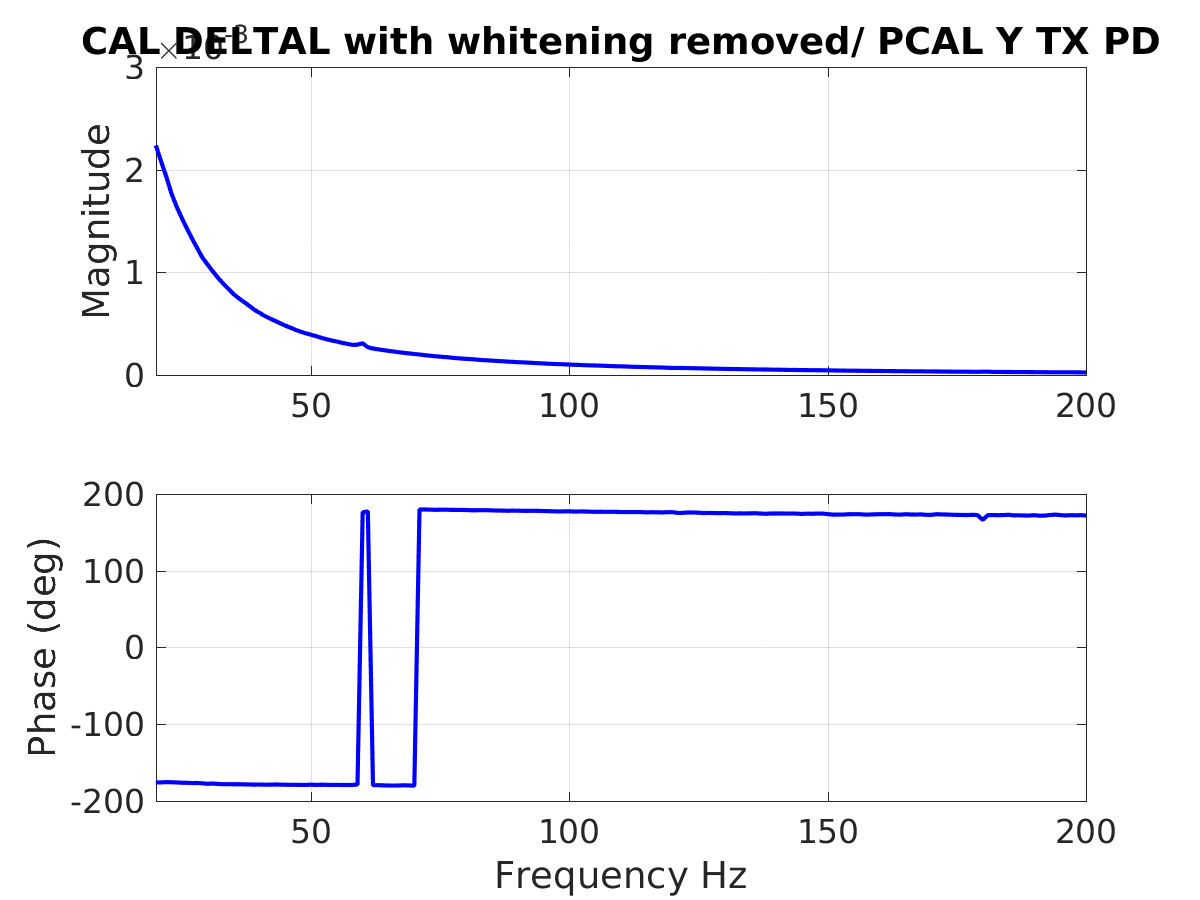
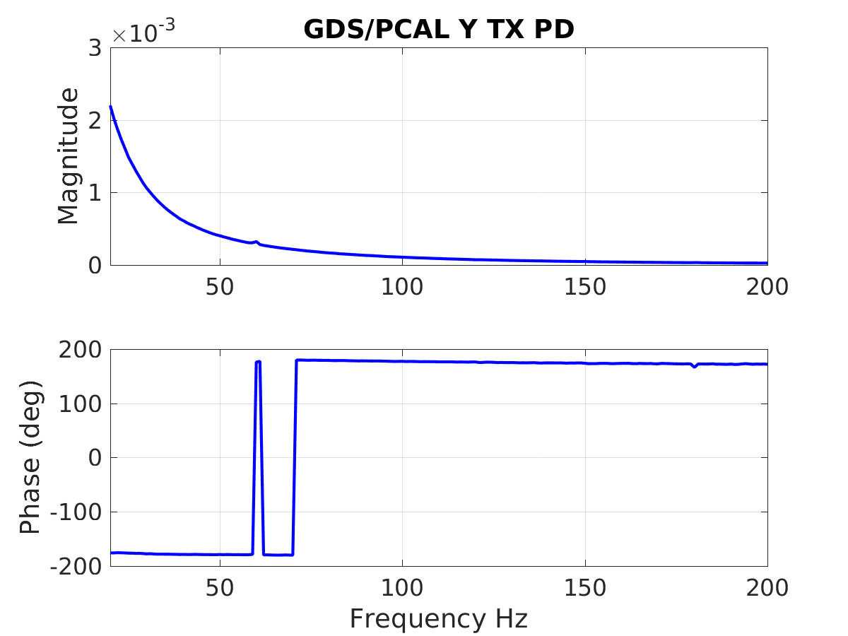
I used the script that Joe B adapted from Shivaraj (44473) to look at data from a broadband injection that Craig did using PCAL Y last night.
The script used is attached, it is also in aligocalibration/trunk/Runs/O3/H1/Scripts/CALCS_FE As Joe said it is only correcting DELTAL for the whitening, and multiplying GDS calib strain by the arm length to calibrate it into displacement.
The sign of the GDS strain channel agrees with the sign of CAL DELTAL. (First attachment).
The sign of both CAL DELTAL and GDS calib strain are wrong (second and third attachments). Craig is injecting on PCAL Y: at DC applying pressure to the highly reflective surface of the optic makes the Y arm longer, which make DARM more negative. We are making this measurement at frequencies above the suspension resonances, which give a 180 degree phase shift. So, if the sign of the calibration were correct, the phase between PCALY excitation and DARM should be 0 degrees. Since we are measuring 180 degrees for both DELTAL and GDS calib strain, we flipped the sign.
We flipped the sign in the inverse sensing function gain, and the actuation sign we flipped for each stage in the CAL CS TM_OUTPUT_MTRX. The sign was flipped at 23:02 UTC March 21st.
This undoes the sign flip from 47574. Since we still think that the logic that led us to flip the "arm sign" filter was correct and it is in agreement with the calibration groups documentation of their sign convention, we are leaving the "arm sign" as -1 for the x arm and +1 for the y arm.
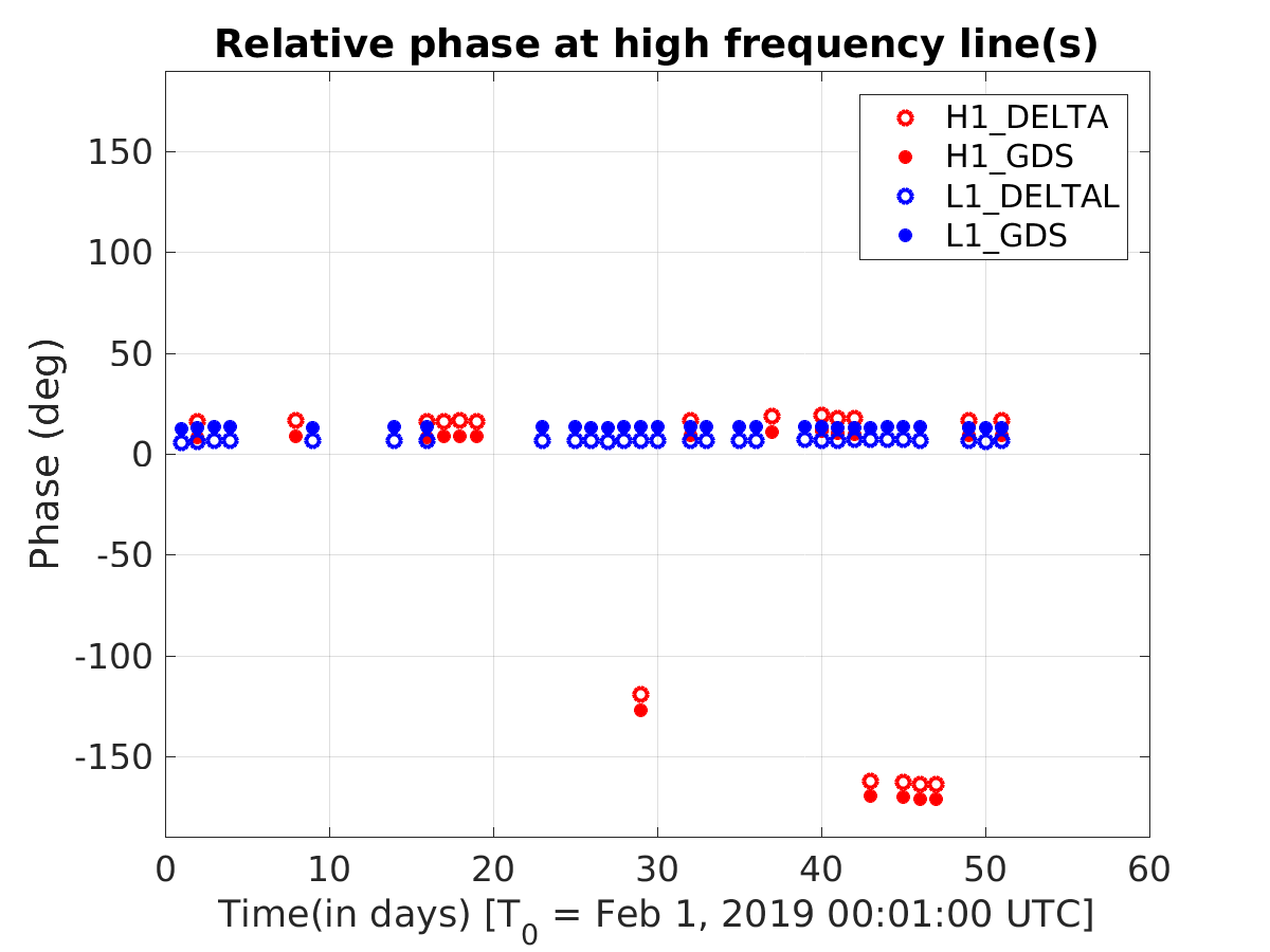
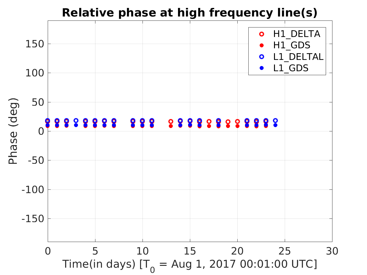
The first attached plot shows the trend of relative phases between PCAL & DELTAL and PCAL & GDS since February 1, 2019 to till date. I sampled one data point per day (at 00:01:00 UTC) and also kept only those points during which the IFO was in low noise. In the plot, I have plotted both H1 and L1 for comparison purposes. I have also added a plot (second png) showing similar comparison during end of O2. These plots suggest that the current sign of both detectors follow the expected sign convention of Lx-Ly. In the first plot we can also see the interim change in the sign of H1 that happened a few weeks ago. I have used the same code base as in the above alog, but just looked at the relative phase at high frequency calibration lines (the ones used for calculating sensing function).
Note: The line frequencies were changed at LLO between O2 and O3 and hence we expect to see small differences due to that.
These changes were accepted into CAL-CS safe.snap, namely, H1:CAL-CS_DARM_ERR_GAIN = 1.03 H1:CAL-CS_DARM_TM_OUTPUT_MTRX_2_2 = -1.0 (ETMX UIM to dL_UIM) H1:CAL-CS_DARM_TM_OUTPUT_MTRX_3_3 = -1.0 (ETMX PUM to dL_PUM) H1:CAL-CS_DARM_TM_OUTPUT_MTRX_4_4 = -1.0 (ETMX TST to dL_TST) We're still working on the documentation to make sense of all this sign stuff.
Jenne, Sheila
After a long talk with Keita and Joe B on the phone we have updated the calibration epics records that are used to calculate the kappas.
Joe walked us through how to update the epics records. We made a new copy of the paramter file in /ligo/svncommon/CalSVN/aligocalibration/trunk/Runs/O3/H1/params/modelparams_H1_20190316.py
We updated the validity time, modelDate, Optical gain, cavity pole, spring frequency and Q based on Craig's fit here. We measured a transfer function from DARM_IN1 to the OMCDCPD sum during last nights lock and used that to update omcdcpdout2darmin1tf There is a parameter for changing the sensing sign in this parameter file, but we have not changed that. It looks like last night's sign flip in the inverse sensing function (47574) didn't have an impact on the kappa calculation here, but we would like to double check with the calibration group that this is OK.
We then followed Joe's instructions to create /ligo/svncommon/CalSVN/aligocalibration/trunk/Runs/O3/H1/Scripts/CALCS_FE/createEPICS_for_20190316.py the only changes we made to this from earlier versions were to point to the new parameter file and to add a new argument to the computeEPICS function for the third pcal frequency (1083).
epics = computeEPICS(pars, f_pcal1, f_uim, f_pum, f_tst, f_pcal2, f_pcal4, f_pcal3)
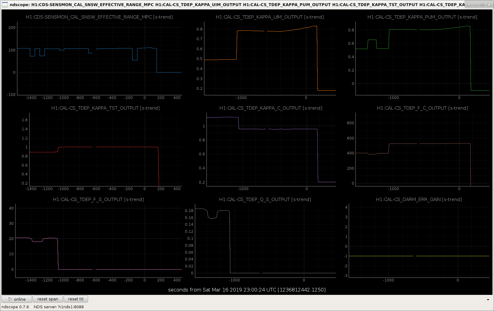
The resulting change to the calcaulted paramters is shown in the attached screenshot, the kappas all seem more reasonable than before, the spring frequency and Q have gone to zero.
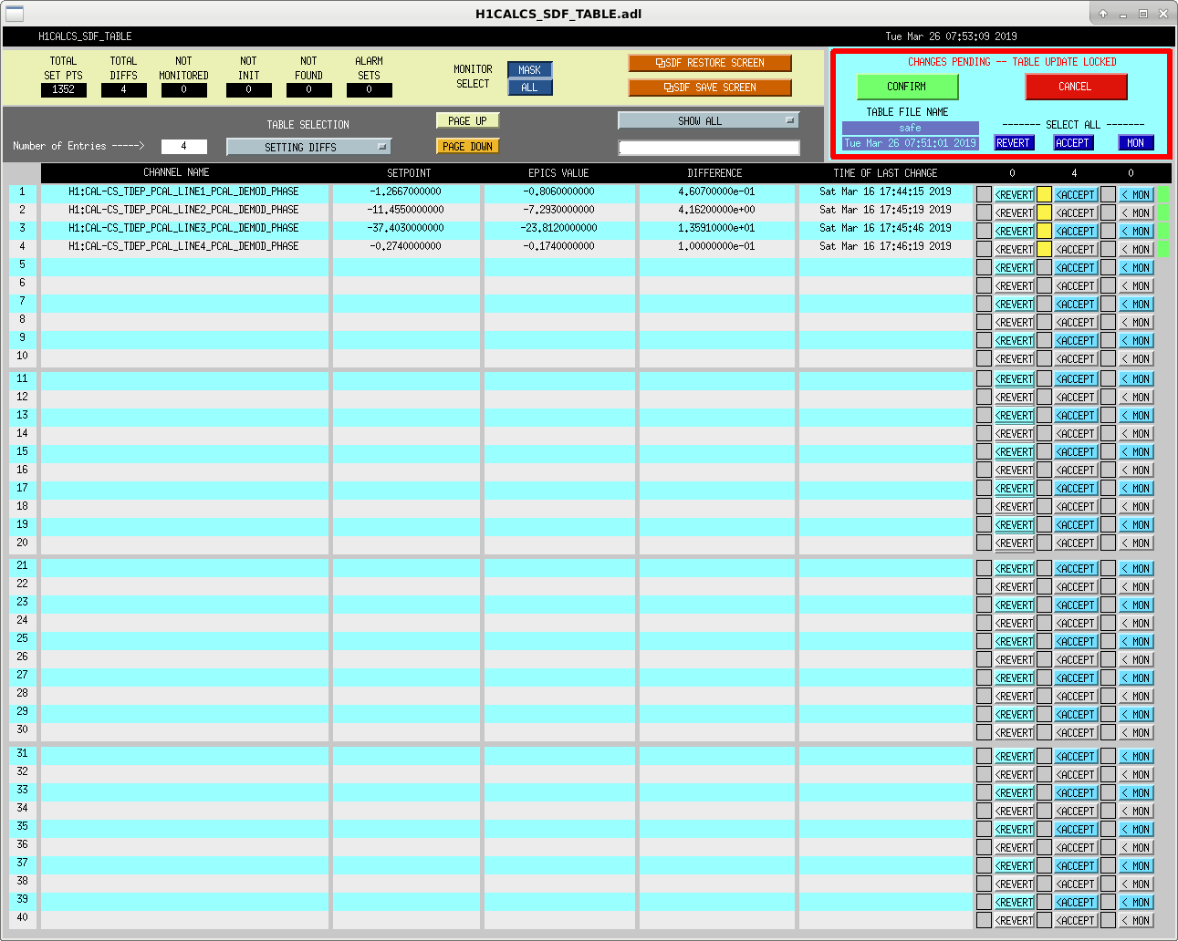
Joe B had told us that we would need to adjust the demod phase for the calibration lines in the front end to get the real time cavity pole (and maybe other factors) correct, related to LLO log 44005 I've added changed the demod phases, setting the demod phase to -360*freq/16384 for each of the pcal demods eg. H1:CAL-CS_TDEP_PCAL_LINE1_PCAL_DEMOD_PHASE
With these phase shifts, the cavity pole is now reading 429 Hz, so this seems good. (To clarify, I didn't mean to say the cavity pole is at it's best possible value, as Peter points out, but that the time depedent factor is reporting a value close to the measured value that Craig posted 47493)
The ideal DARM pole frequency, calculated as in LLO log 41971 and using parameters:
Ts = 0.323Ti = 1.46% (average of the two)re2 = 1 - 35 ppmis frse = 452 Hz.
These changes have beden accepted into the safe.snap of the SDF -- see attached screenshot.