With the common gain slider set to 28 dB and the fast gain slider to 15 dB, a round of transfer function measurements
was executed. The input modecleaner was locked when these measureements were taken. The reference cavity transmission
monitor was ~2.7 when the measurements started.
CG28FG15.txt open loop transfer function to 1 MHz (image CG28FG15.tif)
C28F15.txt open loop transfer function to 5 MHz (image C28F15.tif)
TP3A.txt mixer monitor signal to 1 MHz (image TP3A.tif)
TP3B.txt mixer monitor signal to 5 MHz (image TP3B.tif)
One very noticeable thing is that with the new gain settings, the UGF is quite a bit lower than previously measured.
Additional transfer function datafiles. Input is through TEST2 In, output is at the relevant test point.
TP10-1.txt fast monitor to 1 MHz (image TP10-1.tif)
TP10-2.txt fast monitor to 5 MHz (image TP10-2.tif)
TP9-1.txt PC monitor to 1 MHz (image TP9-1.tif)
TP9-2.txt PC monitor to 5 MHz (image TP9-2.tif)
Both transfer functions look quite odd, and do not resemble those of the spare TTFSS.
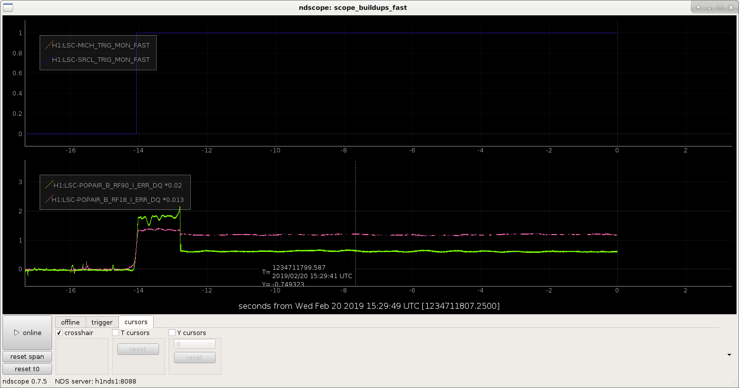
Making note of a time, so we can come back and look at data, but at 15:29:35 UTC on 2 Feb 2019 for a little more than 1 second, PRMI was locked while the SRM was aligned.
This wasn't a PRMI to DRMI transition, it was just trying to acquire DRMI, but still might be a useful time to look at.
Sheila, Georgia, Craig
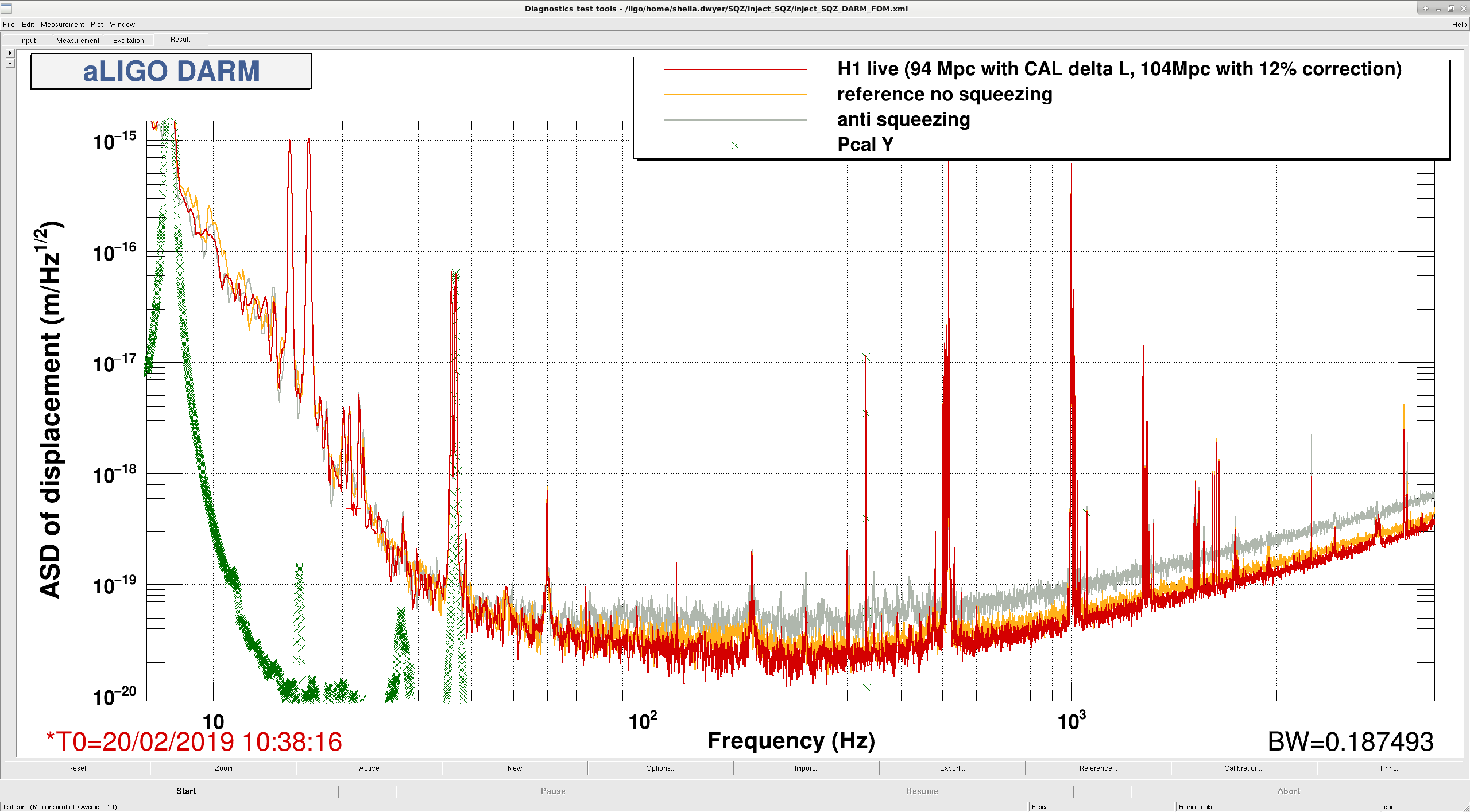
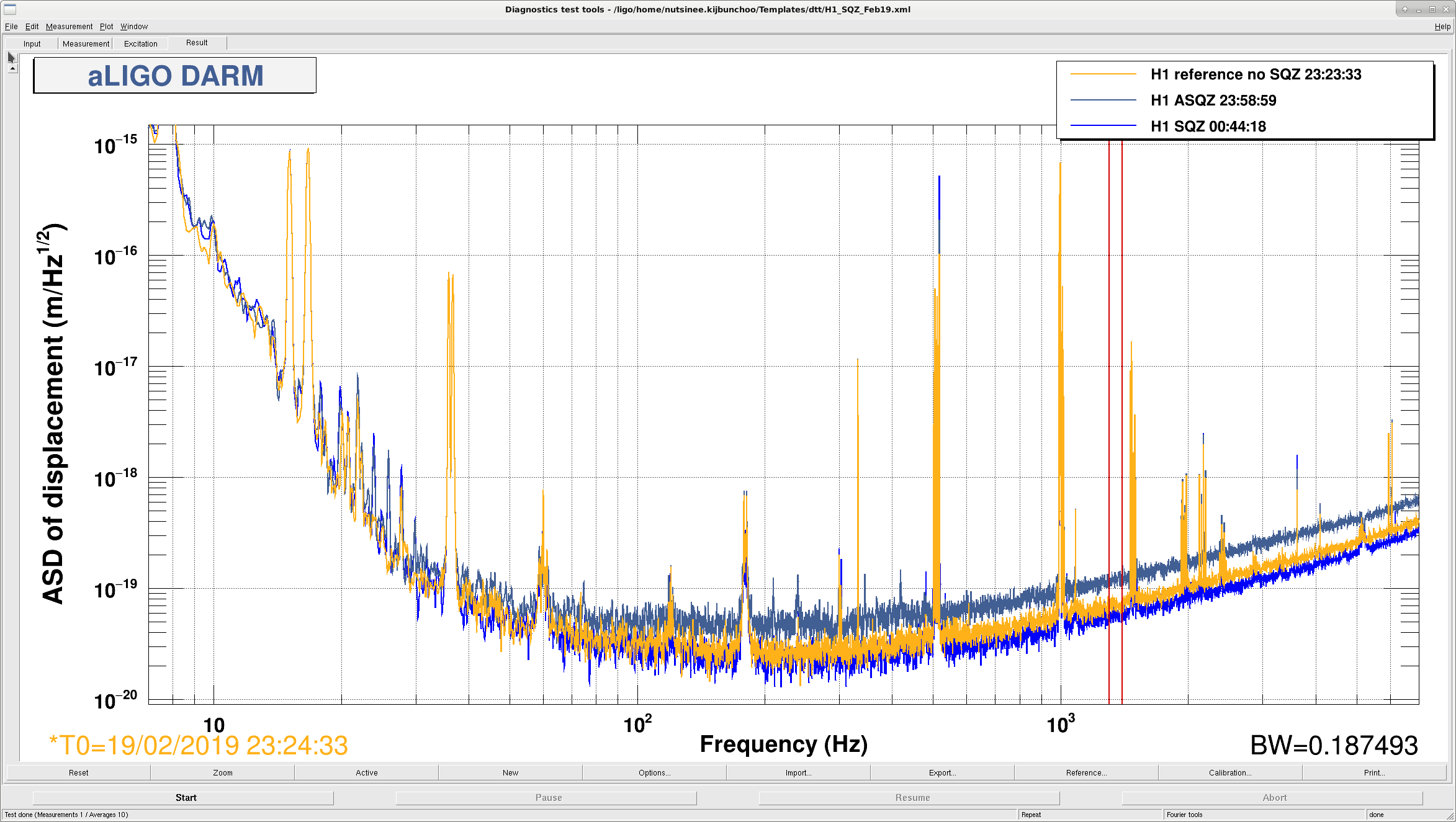
After improving the broad shoulders on the power lines by increasing the OMC dither, 47007, and finding that our 9 MHz coupling to DARM is reduced 47008 and that the DCPD cross correlation shows improved noise around 50-60Hz 47012, we decided to inject squeezing again since we know from 47006 that it can improve our sensitivity. The attached screenshot shows the reference, anti-squeezing and DARM with squeezing. The sensmon range is between 93-94Mpc, and we think that this is underestimating the range by about 12% according to the PCAL sweep that Jeff did this morning 47003.
Wonderful - very nice progress.
Great work!
Excellent news!
Great!
If it were safe to assume that the frequency dependent systematic error were the same between lock stretches (it's not), I could apply the same correction I'd done to the 2019-02-19 23:00 UTC lock stretch to this data. This is a false assumption (and, naturally, the quantification of time-dependent correct factors is back in to the realm of confusing non-functionality so I don't know *how* different parameters are), but hopefully at the ~few% level in response function change, and the effect on BNS range was mapped out in LLO:31156 to be also in the ~few% level. But y'know, because we're crazed to surpass the 100 Mpc BNS range, aka #KeepIt100, I've done the same analysis as was done in LHO:47003, multiplying the ASD at this time (Feb 20 2019 10:38:16 UTC, 1234694314, for 120 seconds) by the previous lock stretch's PCAL 2 DELTAL sweep, and computed the BNS range difference. As a testament to the hilarious comedy of life, the corrected range is 99.91 Mpc. (And note that I tried shifting the ~120 second time stretch by 15, 30 seconds on either side and the range went down to 99.5 ish, so somehow Sheila found a magically delightful time.) This ASD has not had any offline subtraction done, which I believe Team DetChar has been geared up to do. I've updated the function that generates these plots a bit, /ligo/svncommon/CalSVN/aligocalibration/trunk/Common/pyDARM correct_bns_range.py and I *know* that this function as-of-yesterday doesn't work in the control room. Regardless, I quote the exact command line used on my laptop configuration of python: python3.6 correct_bns_range.py --run='O3' --IFO='H1' --GPSstart='1234694314' --GPSend='1234694434' --PCAL2DARMTF='/ligo/svncommon/CalSVN/aligocalibration/trunk/Runs/O3/H1/Measurements/FullIFOSensingTFs/2019-02-19_H1_PCAL2DARMTF_A_PCALYRX_B_DELTALEXT_tf.txt' --PCAL2DARMCOH='/ligo/svncommon/CalSVN/aligocalibration/trunk/Runs/O3/H1/Measurements/FullIFOSensingTFs/2019-02-19_H1_PCAL2DARMTF_A_PCALYRX_B_DELTALEXT_coh.txt' --DARMmodelfile='modelparams_H1_20190219' --modelFunction='modelPars' --resultsTag='/ligo/svncommon/CalSVN/aligocalibration/trunk/Runs/O3/H1/Results/FullIFOSensingTFs/2019-02-20_H1_sensingFunction_BNSRangeCorrection' The data is committed to the CalSVN here: /ligo/svncommon/CalSVN/aligocalibration/trunk/Runs/O3/H1/Results/FullIFOSensingTFs 2019-02-20_H1_sensingFunction_BNSRangeCorrection.pdf 2019-02-20_H1_sensingFunction_BNSRangeCorrection_ASD.txt 2019-02-20_H1_sensingFunction_BNSRangeCorrection_PCAL2DELTALTF.txt
At the time of our excellent spectrum, the offline noise subtraction codes from DetChar (TJ Massenger & Derek Davis) and Calibration (Aaron Viets) gives us about 1.5 more Mpc, so we can say that we really did get above 100 Mpc - in fact about 101.4 Mpc. See, for example, a comparison of cleaned vs. pre-cleaned spectra: https://ldas-jobs.ligo.caltech.edu/~aaron.viets/H1_CAL_NoiseSub_20190220/H1_1234694144_1234698240_spectrum_comparison.png
Sheila, Georgia, Craig, Danny, Dan
Earlier this afternoon we spent some time with the interferometer locked at 2W RF DARM, and made some measurements of OMC length noise, similar to the measurements described here: 30510
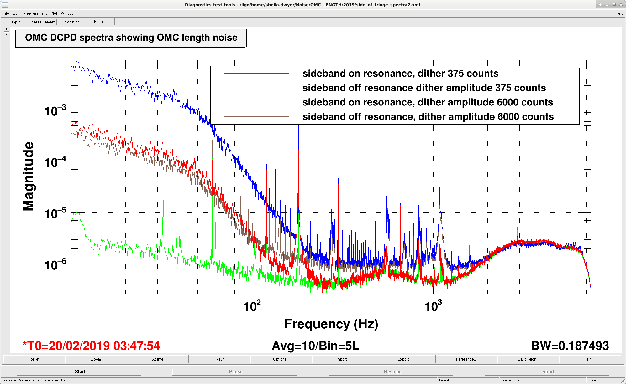
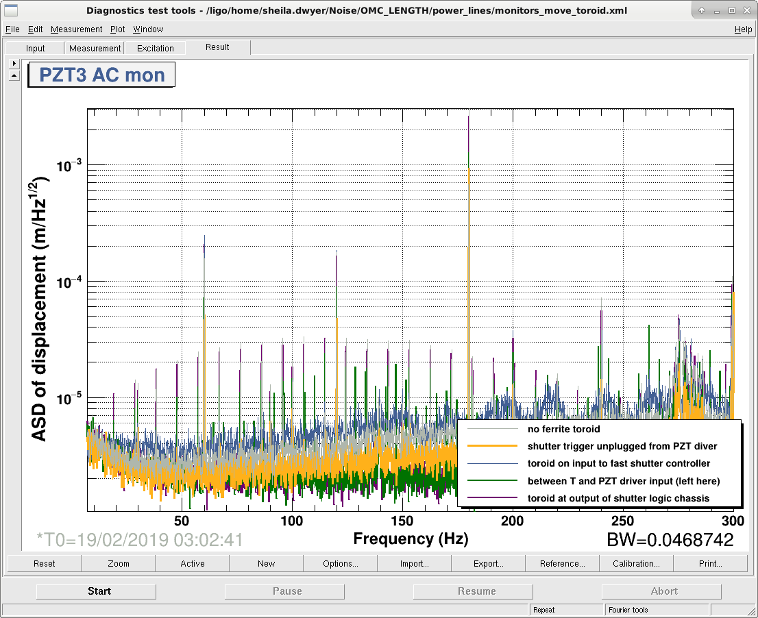
The attached plot shows the noise measured with the OMC locked on the 45MHz sideband, both on resonance and with a small detuning from resonance. With the small detuning, the DCPDs see the OMC length noise, the measurements taken when the OMC is on resonance show the noise floor of this measurement of the OMC length noise. You can see that there are a series of lines in the OMC length that weren't present in the OMC length noise measurements from 2016 linked above, and the comb that appears is the same as the comb seen in the PZT3 monitor, 46982.
The other noticable feature is the wide 180Hz line in the noise measured with the OMC locked on 45 on resonance, which seems very similar to the 180 Hz line which we have been blaming on the modified PZT driver. When the OMC is locked on the sideband the intensity noise on the sideband around the dither frequency is higher than when we are locked on the carrier, so the dither frequency needs to be increased to get a similar SNR. We increased the dither amplitude and saw that shoulders on the 180 Hz line were decreased, meaning that they were upconversion of the dither loop sensing noise onto the 180Hz line which seems to be a new feature in the OMC length since O2.
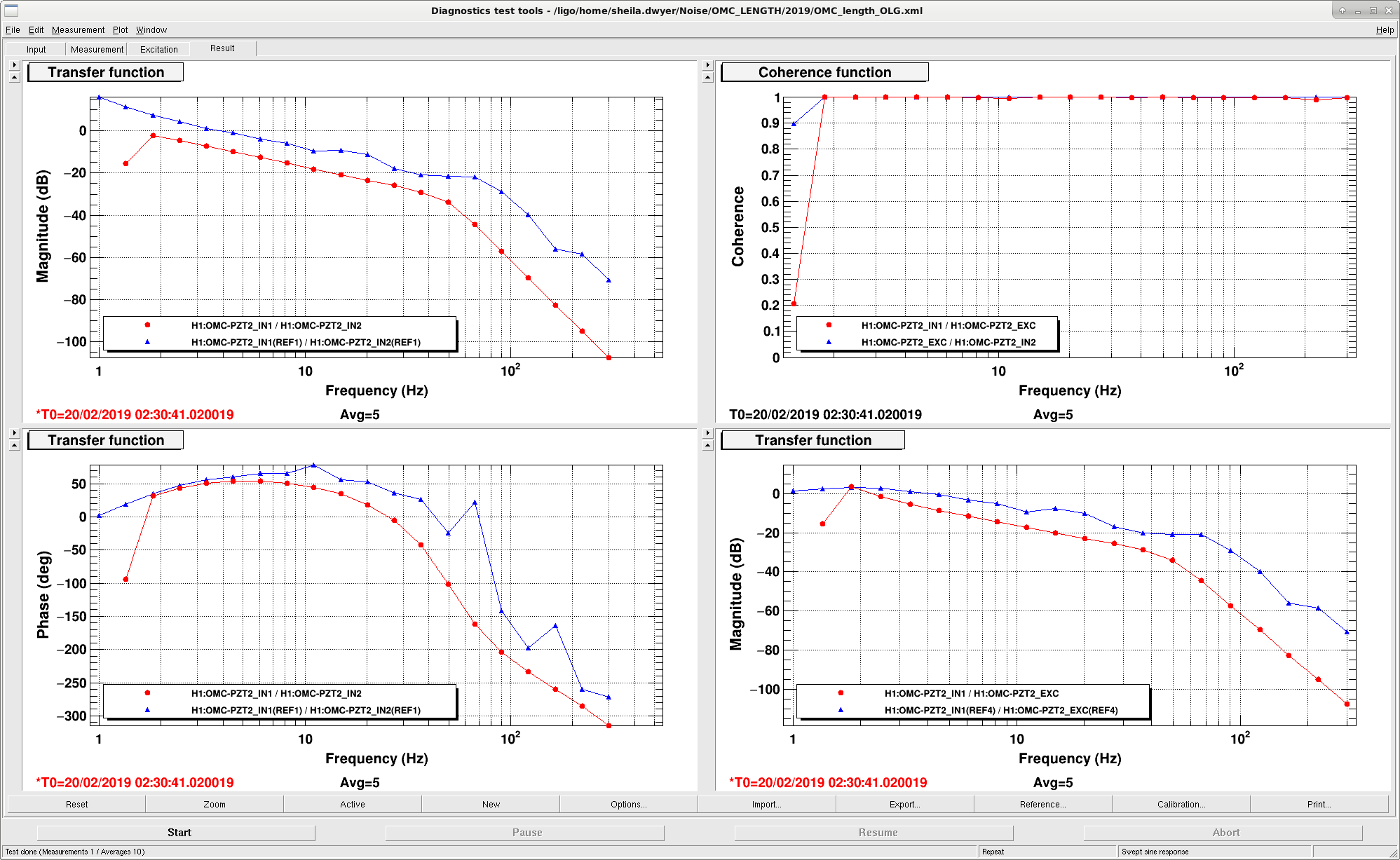
We also measured the OMC length loop UGF before changing the dither amplitude, see second attachment, and it's UGF is low, around 1 Hz. In a similar measurement from December the ugf was almost 4Hz, I've put the template I use to measure this in the userapps/lsc/h1/templates directory (this template is not safe for use in full lock, I use it locked on RF). It seems likely that the reason for the 180 Hz broad peak when we've swapped the driver is that the ugf of the dither loop wasn't compensated for when the dither amplitude changed because of the change to the driver electronics.
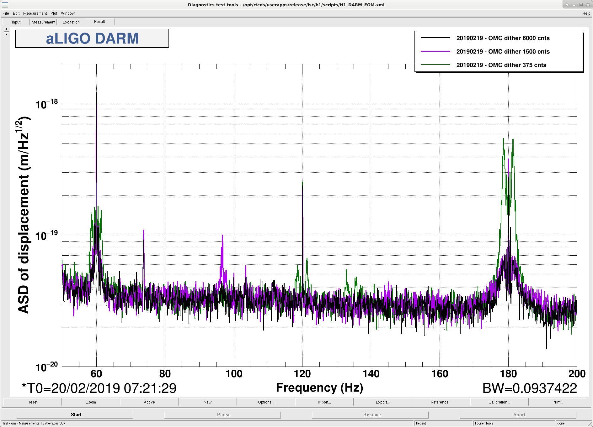
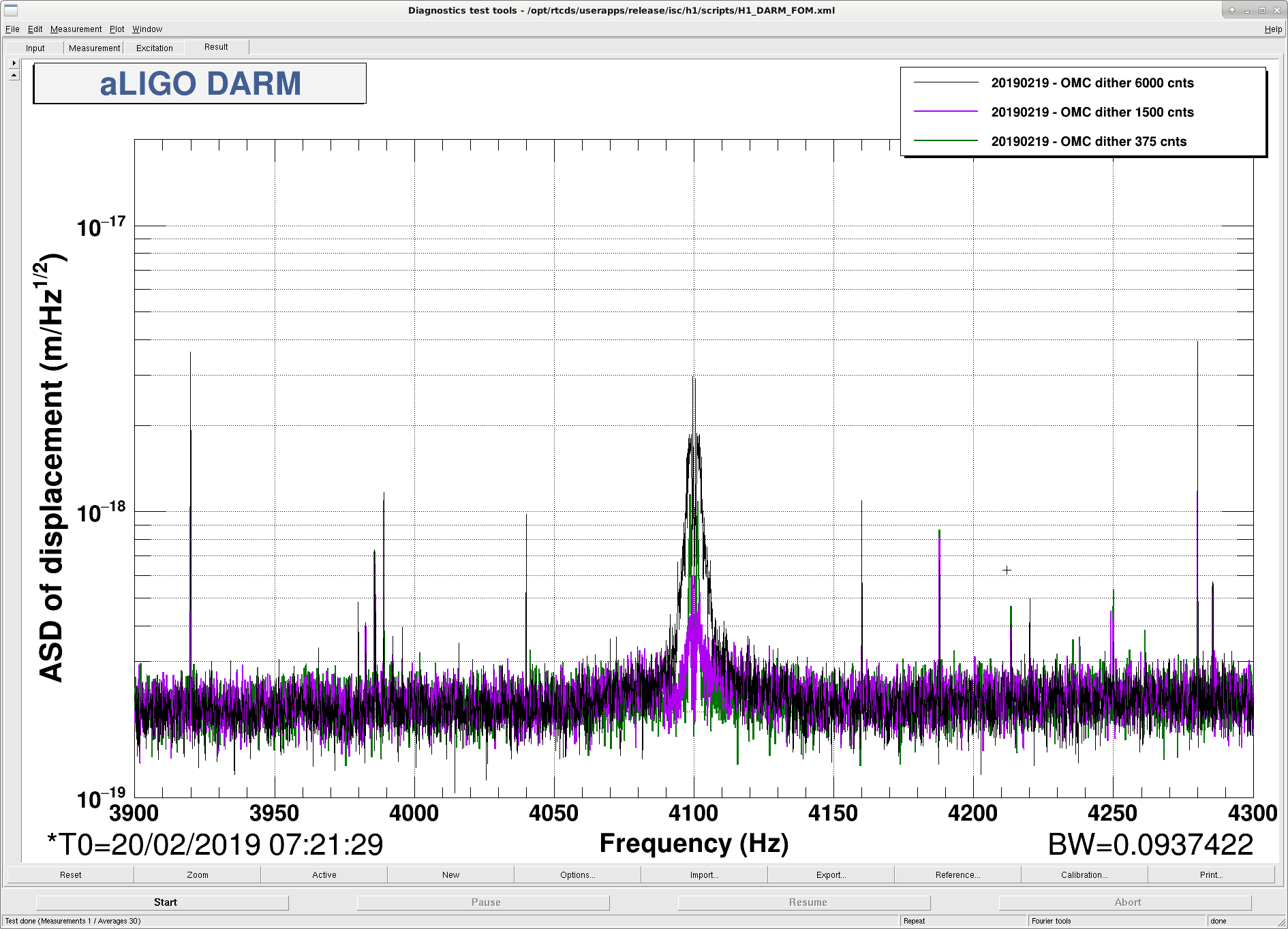
For now we have increased the dither amplitude for locking on the carrier by a factor of 4, which should give us a similar UGF to the one that we had in December. The 3rd attachment shows that we can reduce the shoulders on the 60Hz and 180 Hz lines by increasing the dither line, (the 90Hz peak is unrelated). The 4th attachment shows that when we continue to increase the dither amplitude we start to see the power lines upconverted as sidebands around the 4100Hz dither in DARM.
This improvement gives us a few Mpc (about 4Mpc), which is roughly consistent with Jenne's prediction. It would still be worth spending some time trying to reduce the power lines (and the comb) in the OMC length noise, since there are still shoulders on these peaks, and the OMC length noise spectrum was cleaner in 2016.
Sheila Craig Georgia
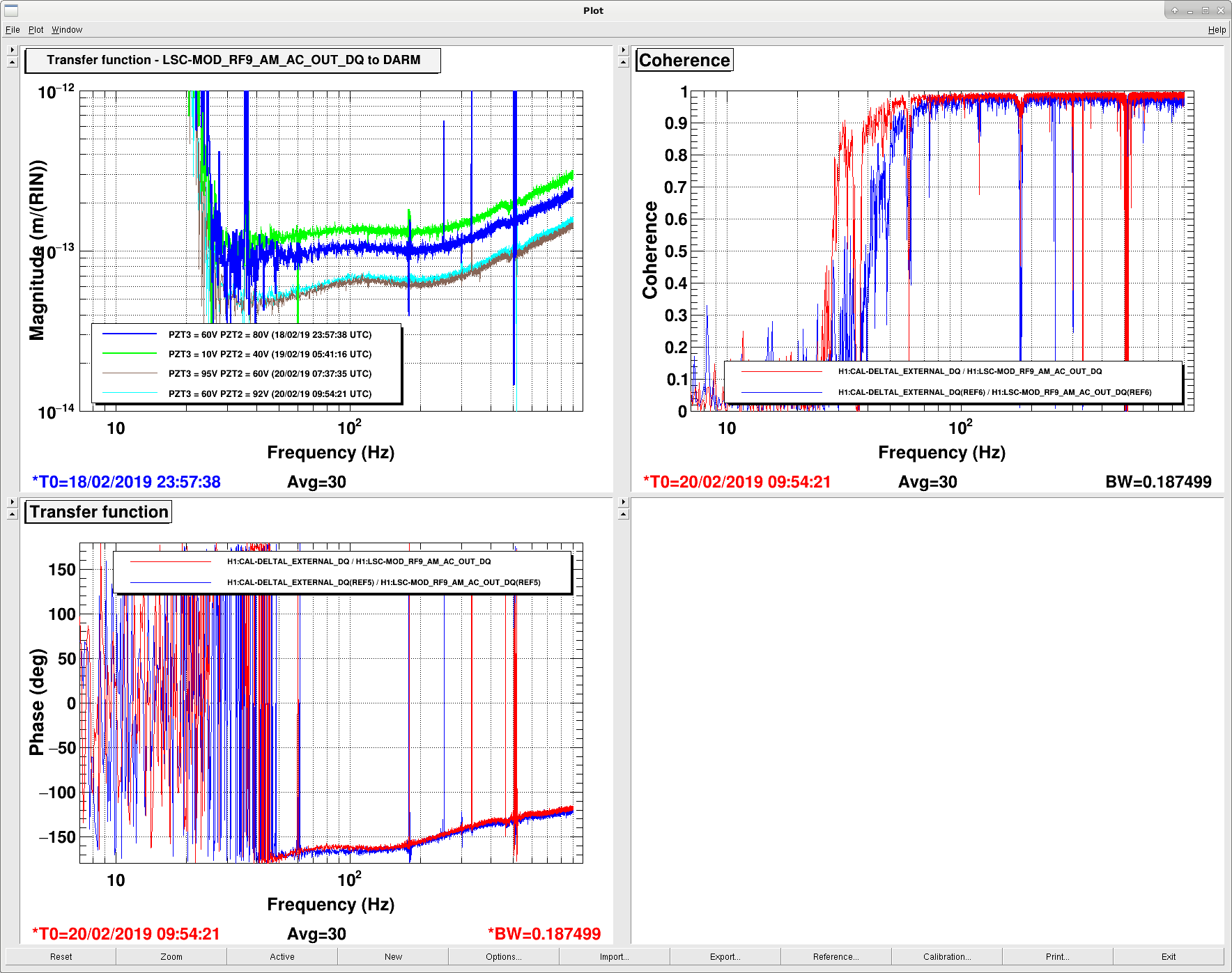
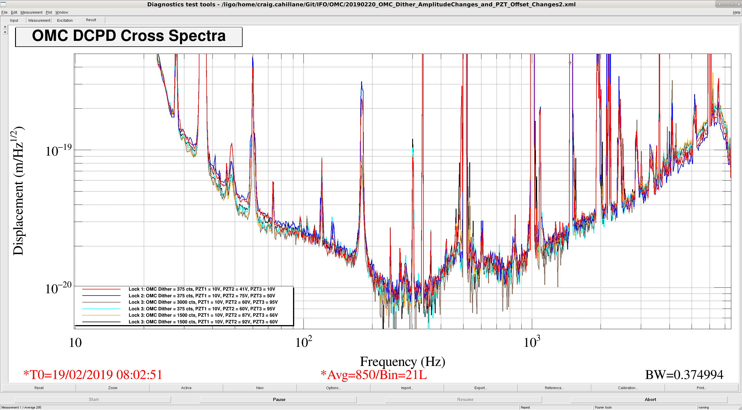
Today locked with an even larger offset on the OMC PZT3 (PZT1). We measured the coupling from RF9 to DARM using the RF amplitude modulation injection (same as Sheila reported yesterday), and found the coupling was reduced by a factor of 2 compared to a lock we had yesterday which had smaller offsets on the PZTs (compare green and brown traces in the attachment). Craig looked at the cross-correlation between the OMC DCPDs and found the cross-correlated noise in the ~50Hz band was also lower compared to yesterdays lock.
We then changed the offset on the PZT within the same lock to try and change the RF9 to DARM coupling. We stepped the PZTs all the way back to the same configuration as two days ago (compare blue and cyan traces), and found there was little change in the RF9 to DARM coupling. So the conclusion is the RF9 to DARM coupling is changing from lock to lock, but it is not the OMC PZT offset which is causing this change.
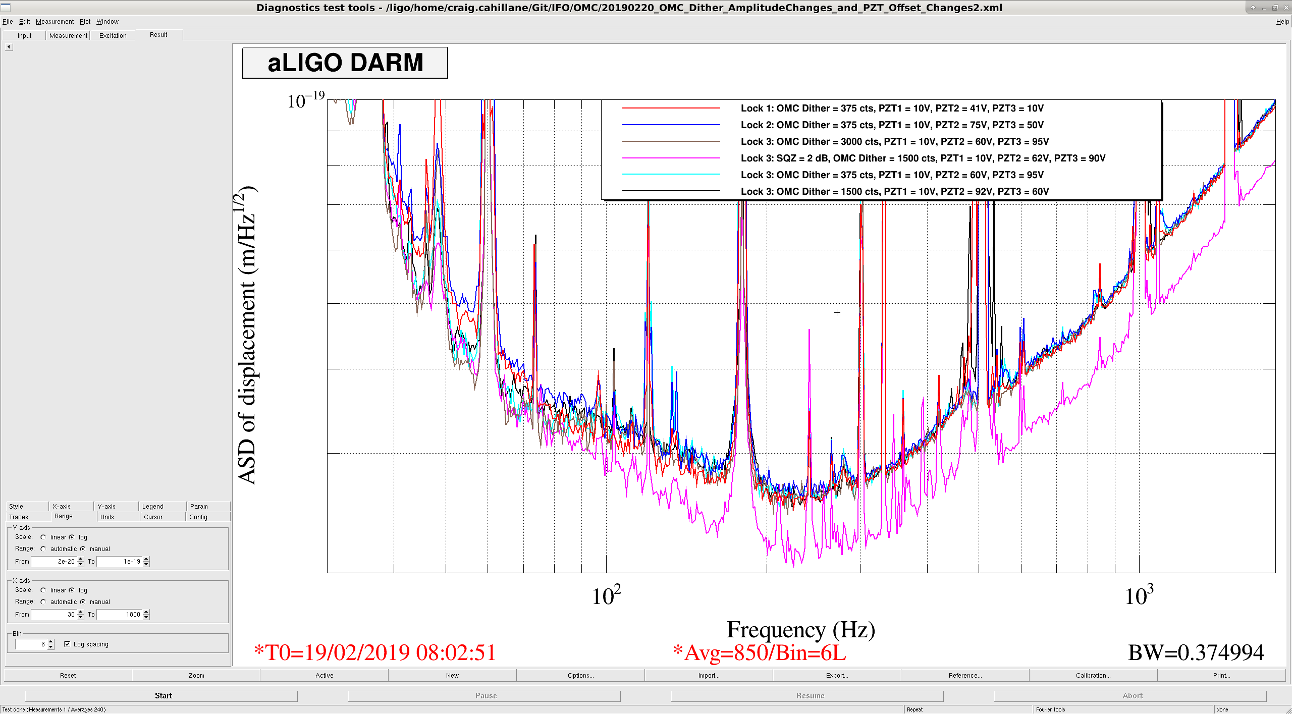
I took some CSDs of the DCPDs to look at the correlated noise of the IFO to see whether the OMC PZT voltage changes or OMC LSC dither amplitude changes helped the coupling to DARM. During the lock tonight (Lock 3 in the legends of attachments one and two), we have seen ~15% lower DARM noise in the 40-80 Hz region. This seems to be because 9 MHz RIN coupling to DARM is lower (seen above). Moving around the OMC PZT voltages does not affect the 9 MHz RIN to DARM coupling. Also the OMC LSC dither amplitude was increased from 375 to 6000, 3000, and 1500 cts. This also did not affect the 9 MHz RIN to DARM coupling. We have left it increased to 1500 cts due to the reduction seen in the 180 Hz shoulders. Simple DARM Noisebudget After taking the DCPD cross spectral densities I began wondering what limited the CSD. I retook the intensity noise projection into DARM based on the extra 12 dB of suppression added to ISS second loop, and plotted the intensity projection, frequency projection, DARM correlated noise with 850 averages, and DARM ASD with 2 dB squeezing. (The correlated noise spectrum was spoiled by squeezing, so I have used the non-squeeze CSD of DCPD A and B) There is a distinct shift in the correlated spectrum at around 200 Hz. Above 200 Hz, I think we see only the remainder shot noise of the imperfectly balanced DCPDs. With 850 averages and perfect balance, we should be able to find resolve coherent power at around 1/850 ~ 0.001, but we are able to achieve an DARM ASD ratio of around 1/2 for DARM CSD/DARM ASD, which is (1/2)^2 ~ 0.25 coherence. We ought to be able to balance our PDs a bit better. At 5000 Hz we see some approximately equal combo of intensity and frequency noise. Both are low enough to not limit us even with 2 dB of squeezing. Below 200 Hz, correlated noise dominates. Today this correlated noise between 40 and 80 Hz was slightly better due to this 9 MHz RIN coupling improvement that we don't understand. 30 Hz and below is likely mostly ASC noise. Probably the most important mystery is what is going on at 100 Hz. There is some shelf of correlated noise DARM is sitting on that gives way around 200 Hz. We see some improvement in DARM at 100 Hz from squeezing, so at least some of the noise there is shot noise. With squeezing we are revealing more of the true limiting noise here.
Sheila, Nutsinee
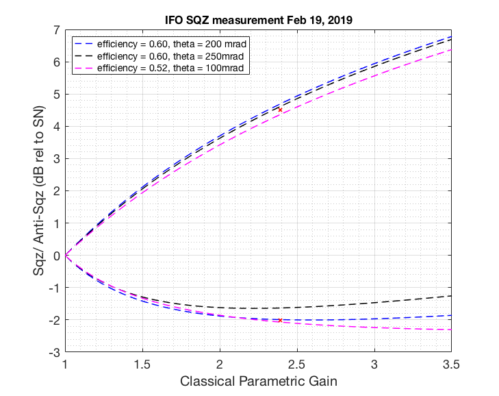
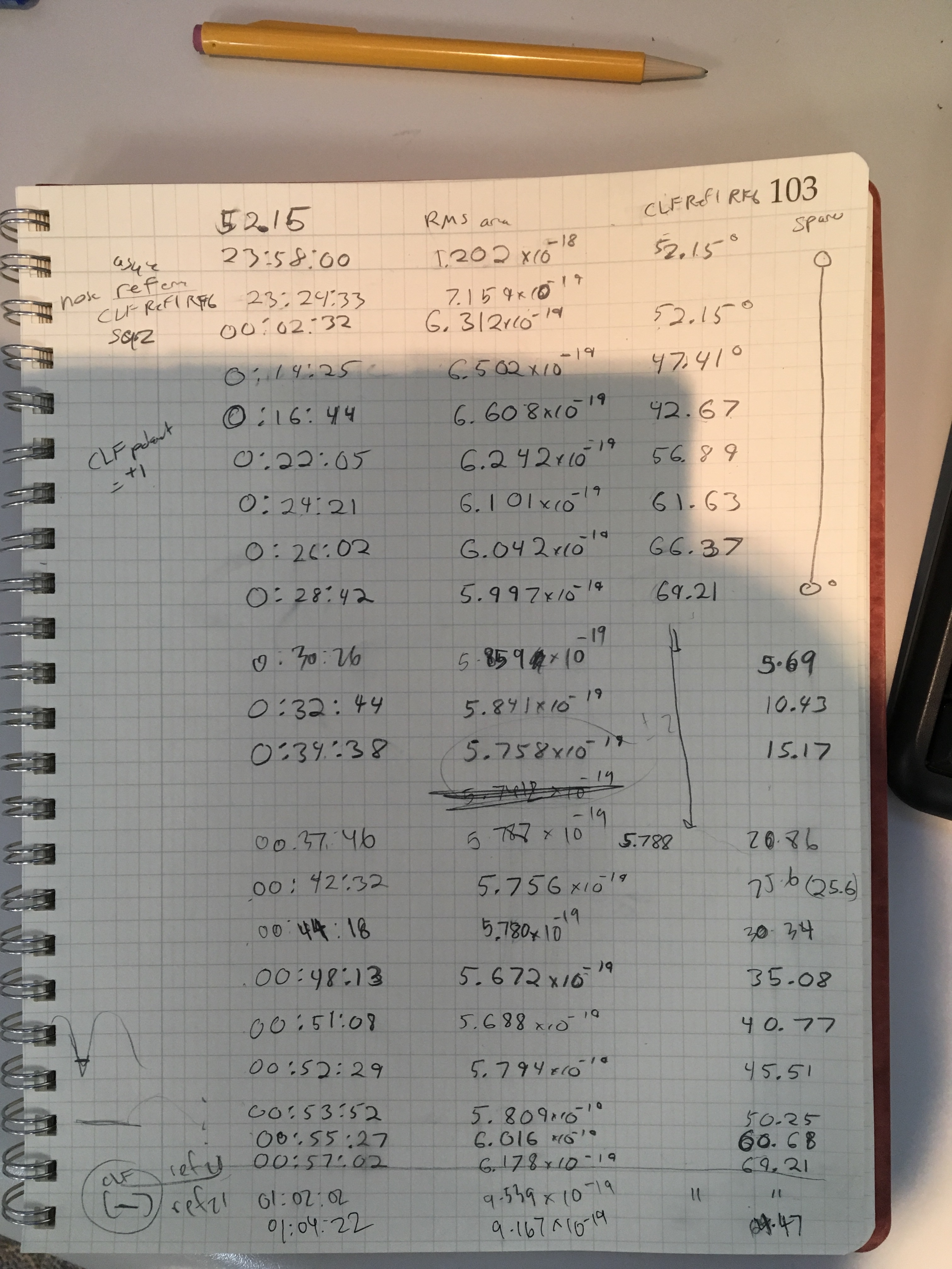
Today we took our time to carefully map out phase vs. amount of squeezing we get. Turned out the best squeezing can't simply be judged by looking at QMON (although I believe this works for asqz). In the end we were able to get 2.02 dB of sqz and 4.5 dB of asqz at a nonlinear gain of 2.39. This measurement still indicates a significant amount of loss. Optimizing the CFL phase is probably what helped the phase noise here. We think we could be limited by some technical noise (to be calculated). But attached below a usual sqz/asqz fit. It seems like our loss is approximately the same as last time (30-40%, alog46814) with better phase noise. We also got a little more RF3 today (-14.7dBm compared to -15.5 dBm last time). We used the same amount of CLF power as last time.

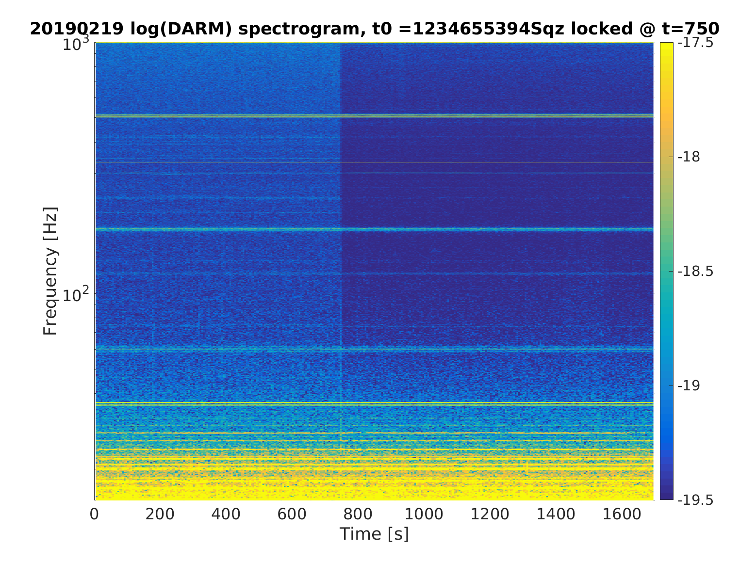
When the beam diverter was opened to inject squeezing this evening we noticed that the 20-29Hz DARM BLRMS got noisier. I made a quick spectrogram and it looks like there are lines at roughly 24 Hz, 26 Hz, 30 Hz, and 32 Hz that show up when the beam diverter is opened. In the first attachment the beam diverter is opened at ~t=500s. Note that the squeezing angle was unlocked for the duration of this spectrogram.
The second attachment shows the spectrogram up to 1kHz when the squeezing angle was locked, showing satisfying broadband noise improvement upon locking.
Since apparently you gain one dB at each attempt, you just need to do squeezing injection one more time! :-D
Great progress, well done!
Very cool! Take that, infinite sea of noisy energy.
Do you see a time dependence or fluctuation in the RF3-Q? That might indicate that some of the loss is time-dependent (and will be removable by controls).
One pedantic note about your plot. It looks like your X-axis is really the nonlinear gain you quote above. Since the seed field you use to measure NLG is injected through a different mirror, it is not measuring the parametric gain that the vacuum is squeezed by, so I wouldn't use that label. The vacuum is a reflection from the cavity M1, not transmission between M2 and M1 like the diagnostics fields. If you do use that label, then you should pass the NLG through the NLG->dbs formula and plot vs. "generated squeezing".
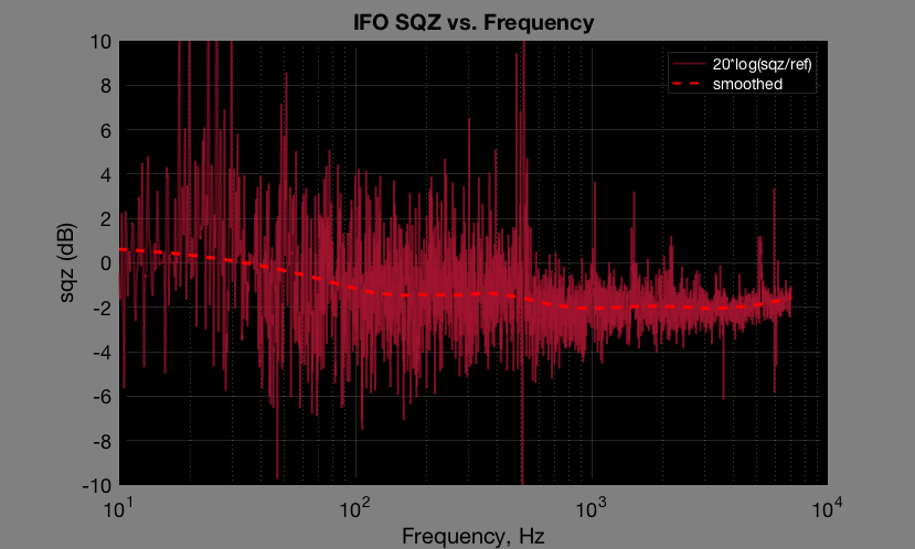
Attached frequency dependent sqz level plot. I divided squeezed spectrum by the reference, turned that into dB and then plot the average (using smooth() function in matlab).

We were moving CLF phase pretty much the whole time we were squeezing so I can't say there is or there isn't a time dependent Qmon fluctuation.
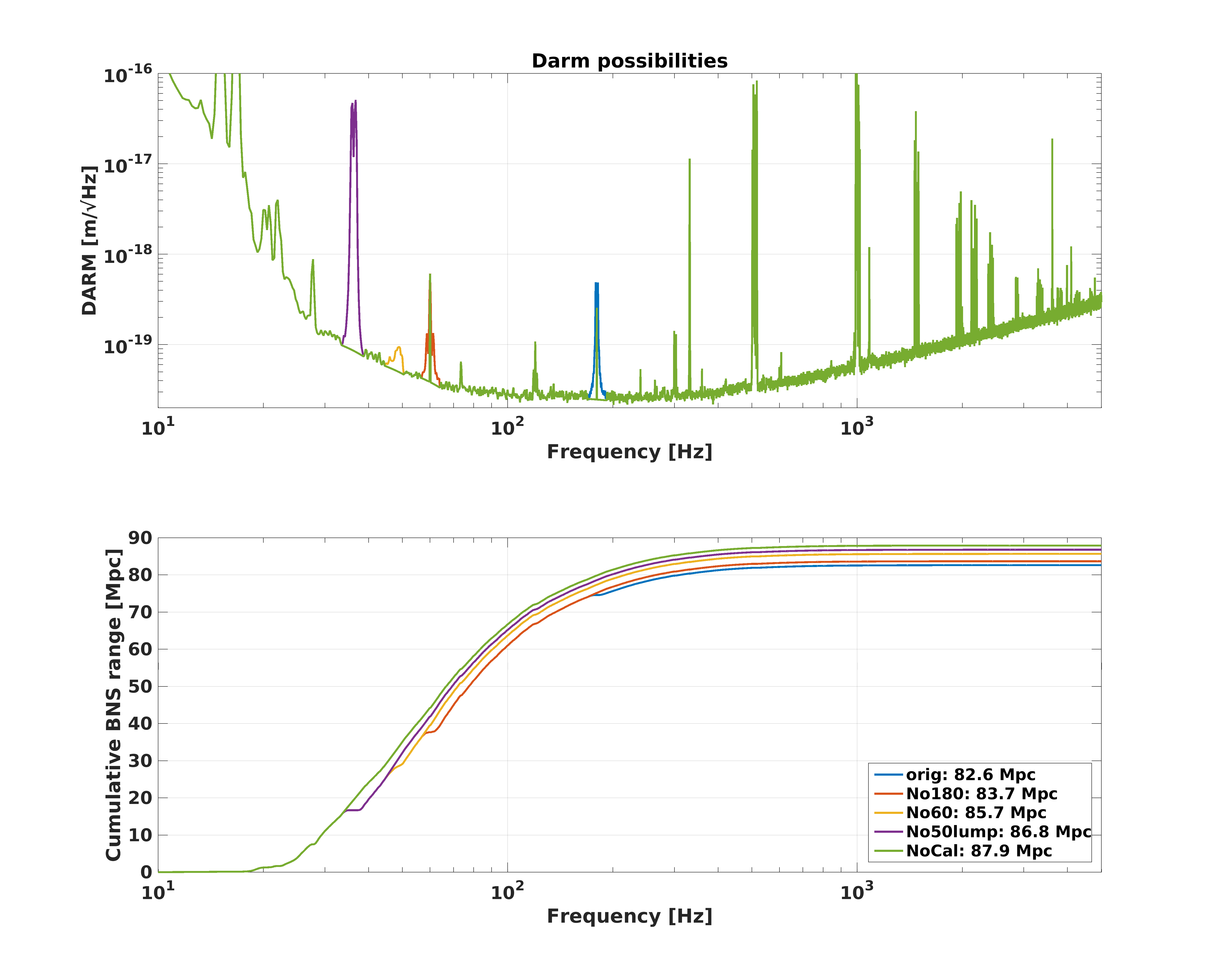
In order to get a rough idea of how much range we're losing to the 60 Hz and 180 Hz broad peaks, I've done a crude interpolation of what our DARM spectrum would look like without them. Short answer: If we could get rid of the 60 Hz, 180 Hz, and also the lump that comes and goes around 50 Hz, we'd have about 6 5 more Mpcs. Note that the absolute value of the calibration is not at all certified (Jeff took more sweeps this afternoon), but the general ~8% improvement is reasonable. EDIT: Now using the Darm spectrum with Pcal correction from Jeff's alog 47003.
In the attached figure, the blue trace is the original spectrum from 19 Feb 2019 08:03:45 UTC the time that Jeff calibrated. Orange-y red is if I cut out the 180 Hz peak. Yellow is if I also cut out the broad 60 Hz peak. Purple is if I get rid of the lump around 50 Hz. Finally, green is if I also cut out the 35 Hz calibration lines (which we know we can subtract offline), for about an 8% 6.4% total improvement over the original (82.6 Mpc to 87.9 Mpc)
This doesn't include the calibration effects that JeffK measured today (an extra few %), or the squeezing that Nutsinee and Sheila measured later today (another extra several %), so the actual absolute range we can achieve is higher than the numbers on my legend here. It also doesn't include the removal of ASC and LSC noise, which for a time a few weeks ago gave us another ~4% (alog 46756).
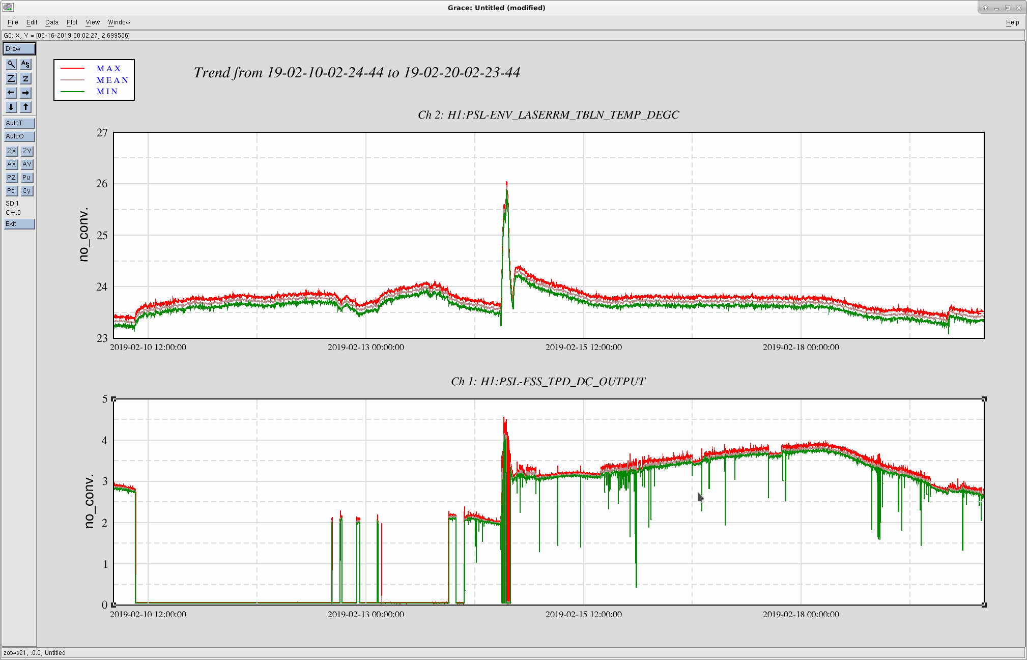
Attached a plot of the FSS trans power over the past 10 days. FYI.

J. Kissel, E. Goetz Since we haven't had a number to reflect the answer to perennial question "what's the status of the calibration?" in what *feels* like a long time (the last time we were able to quantify its badness was on on 2019-01-31, based on a measurement from 2019-01-18, see LHO:46723), I've been given time to take a PCAL to DELTAL_EXTERNAL sweep today. As a result of successfully gathering this sweep, I was able to -- offline -- correct all* systematic errors in the DELTAL_EXTERNAL ASD, and compute the range -- at one time -- 120 seconds of data starting at 2019-02-19 23:00 UTC. This time was a thermally stabilized, and otherwise undisturbed with all calibration lines on. The plot aide is attached, but the sweep indicated a frequency dependent systematic error with excursions as high as 20%. The conclusion is that DELTAL_EXTERNAL is under-reporting H1's range by (85.45 - 75.35)/85.45 = 0.1182 ~ 12%. *This is, of course, assuming PCAL is a perfect calibrator. It should be damn close as the PCAL Y recently had a tune-up and remeasure of its force coefficient -- see LHO:46695, but I only balk a bit because of the recent evidence for clipping -- see LHO:46847. While I can't specifically attribute the systematic error to any one thing, I can point you to an aLOG in which I describe the current (well -- 2 weeks ago now) status of what I believe I need to do in order to correctly *remove* this systematic error: LHO:46806. Sadly, because of the snow-blizzard and lack of person power, I haven't made much *tangible* progress at all. The data lives here: (1) 2019-02-19_H1_PCAL2DARM_TF_5t1100Hz_8min.xml [Contains both DELTAL / PCAL and C/(1+G) measurements] (2) 2019-02-19_H1DARM_OLGTF_5to1100Hz_20min.xml [Contains both G and 1/(1+G) measurements] (3) 2019-02-19_H1_OMCDCPDSUM_to_DARMIN1.xml [Contains information to turn DARM IN1 counts roughly into DCPD SUM Current in "mA"] Note -- I only *need* needed measurement (1), but I was generously given a bit more time. I've worked my way through using Evan's command line function, /ligo/svncommon/CalSVN/aligocalibration/trunk/Common/pyDARM/correct_bns_range.py It required I create a new loop model, /ligo/svncommon/CalSVN/aligocalibration/trunk/Runs/O3/H1/params modelparams_H1_20190219.py The exact command line sequence I used for the function is python3.6 correct_bns_range.py --run='O3' --IFO='H1' --GPSstart='1234652418' --GPSend='1234652538' --PCAL2DARMTF='/ligo/svncommon/CalSVN/aligocalibration/trunk/Runs/O3/H1/Measurements/FullIFOSensingTFs/2019-02-19_H1_PCAL2DARMTF_A_PCALYRX_B_DELTALEXT_tf.txt' --PCAL2DARMCOH='/ligo/svncommon/CalSVN/aligocalibration/trunk/Runs/O3/H1/Measurements/FullIFOSensingTFs/2019-02-19_H1_PCAL2DARMTF_A_PCALYRX_B_DELTALEXT_coh.txt' --DARMmodelfile='modelparams_H1_20190219' --modelFunction='modelPars'
The BNS range corrected strain data can be found attached here, and committed to
/ligo/svncommon/CalSVN/aligocalibration/trunk/Runs/O3/H1/Results/FullIFOSensingTFs/
2019-02-19_H1_sensingFunction_BNSRangeCorrection.txt
Processed the sensing function. Added more points at low frequency to hope resolve the detuning parameters. More details to come.
Removed and replaced the annulus ion pump for GV9 at Y-Mid. No issues were encountered during the replacement, after the new pump was installed the annulus system was pumped for about 3 hours with an aux pump cart. After 3 hours the ion pump was able to maintain vacuum, at which time the aux cart was decoupled and turned off. GV9 annulus system back to nominal.
Done under WP#8091.
Dan, Richard, Jonathan, Carlos, Dave:
h1fw0 is back online writing frames. Dan configured E18-0 POD-1 to rebuild its raid while it is being used by the frame writer.
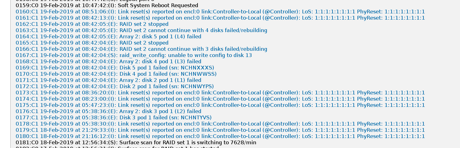
Attached E18 log shows that the problem started at 21:16 PST Mon night, with a repeat at 21:29 and then a disk failure at 05:47 today, at which point I suspect the audible alarm sounded. Problem then became critical at 08:42 with a pod failure, and the frame writer stopped running at 08:44 (all times PST).
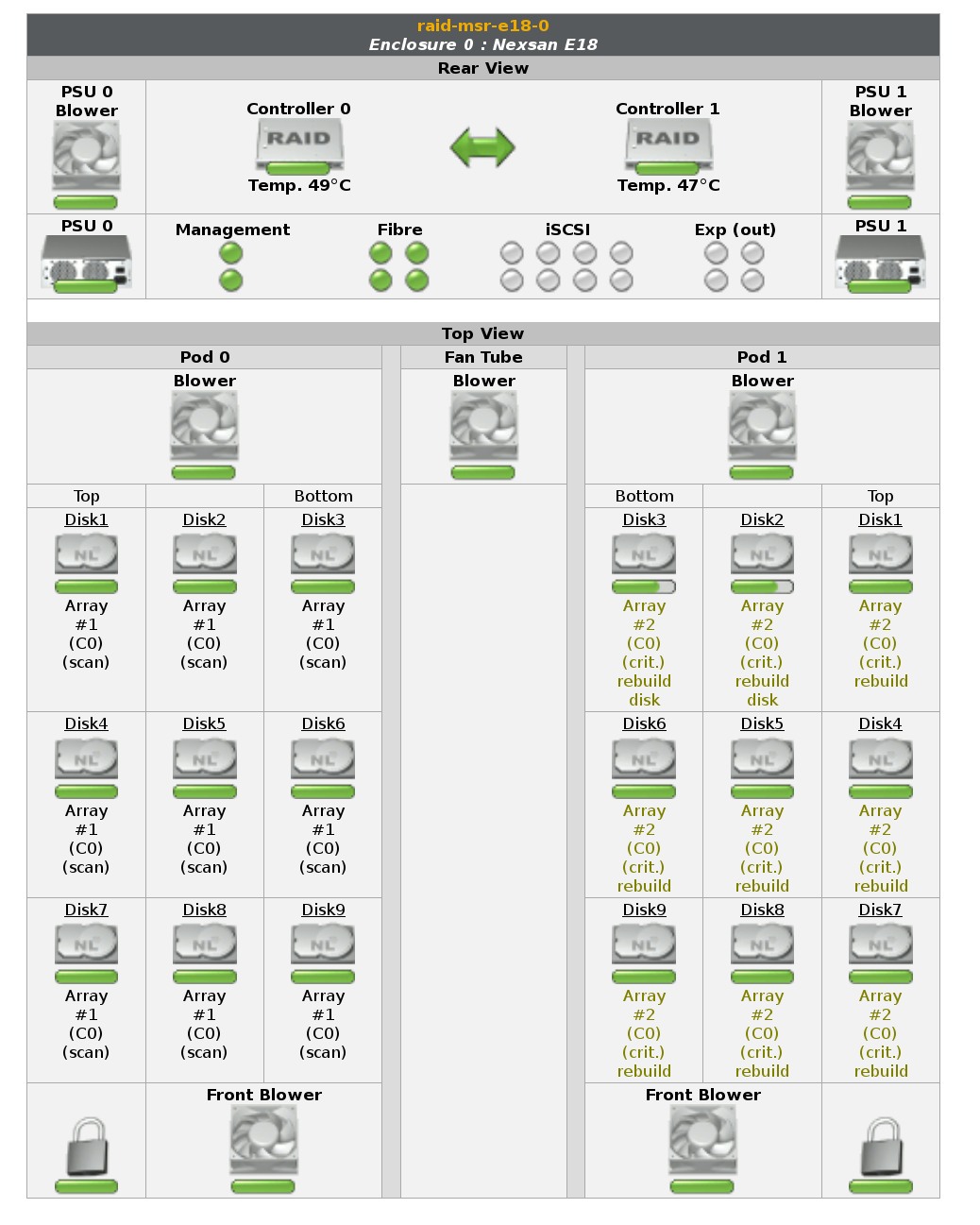
Attached E18 status screen shows POD-1 disk3 and disk2 are actively being rebuilt (green bar is animated growing left-to right), the other disks of POD1 are flashing green-yellow showing they belong to a degraded raid.
Frames gap on hfw0:
-rw-r--r-- 1 controls controls 1.6G Feb 19 08:46 /frames-0/frames/full/12346/H-H1_R-1234629632-64.gwf
-rw-r--r-- 1 controls controls 1.6G Feb 19 11:16 /frames-0/frames/full/12346/H-H1_R-1234629952-64.gwf
FRS12353 was reopened following new developments.
Dan sent our E18-0 logs to the manufacturer (Nexsan) who responded with a recommendation that we 1) upgrade the firmware in the controllers and 2) reseat the controllers.
WP8093 was opened to cover these operations. In staggered sequence, Dan upgraded the firmware and rebooted both controllers. He then removed and reseated the controllers. Controller-0 had no issues, but when controller-1 was reseated it failed. We are hoping the original problem was due to a flakey controller-1, which only came to a head when the card was hard rebooted.
Dan is in contact with Nexsan for a replacement controller card to be shipped to LHO, in the mean time we will operate h1fw0's raid with no redundant controller.
Throughout these operations h1fw0 continues to write frames with no interruption.
I'll extend WP8093 to cover the controller replacement.
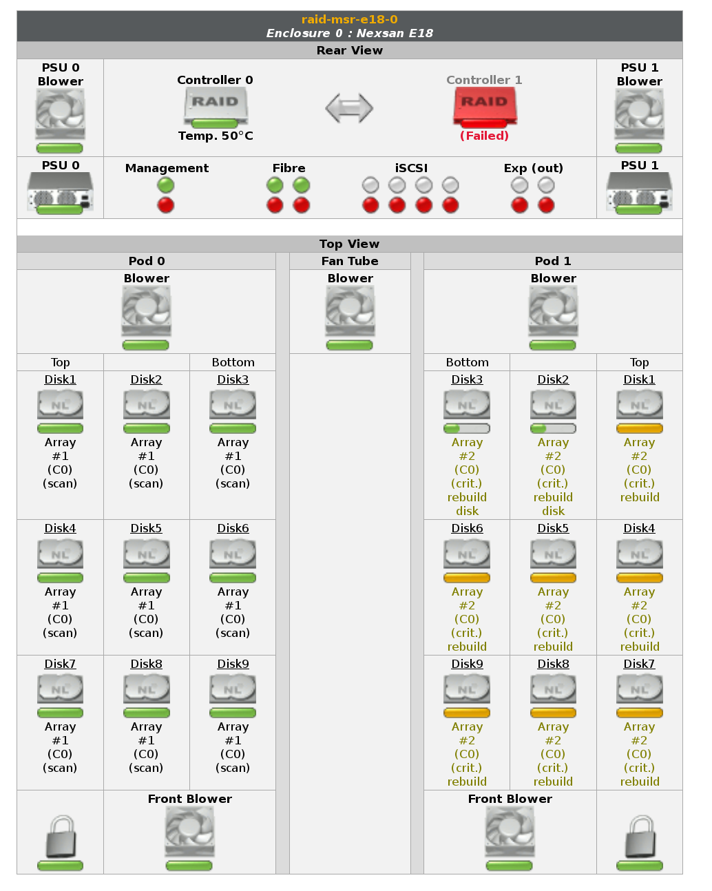
Image of E18-0 status showing failed controller-1
WP 8092
Unit was placed on a temporary HV power supply. This is part of the 180 Hz noise seen in DARM, alog 46839.
After last nights testing showed this did not help. I have removed the temporary supply.