Displaying reports 43161-43180 of 88637.Go to page Start 2155 2156 2157 2158 2159 2160 2161 2162 2163 End
Reports until 13:32, Friday 08 February 2019
LHO FMCS
bubba.gateley@LIGO.ORG - posted 13:32, Friday 08 February 2019 (46873)
Remove Temperature Sensor (B) from the PID Loop at each End Station
Per request from Robert Schofield, I have taken one temperature sensor, (sensor B) out of the PID Loop at both end stations. This will take some time to equalize the temperatures in the VEAs. 
These sensors can be added back if needed.  
H1 ISC
gabriele.vajente@LIGO.ORG - posted 13:32, Friday 08 February 2019 (46872)
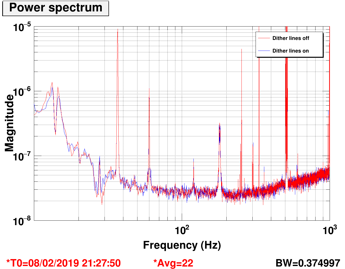
Dither lines off doesn't reduce the noise

With some of the dither lines below 10 Hz, and some at 20 Hz, the low frequency noise is limited by ASC.

I switched off briefly the dither lines and hold the output of the dither loops, to check if the increased ASC coupling is due to the RMS induced by the dither line angular motions.

The answer is: no.

Images attached to this report
H1 ISC (ISC, SUS)
rich.abbott@LIGO.ORG - posted 11:31, Friday 08 February 2019 - last comment - 14:25, Friday 08 February 2019(46870)
More Changes to OMC Piezo Drive
Fil, Dean, Richard, Rich

After removing the newly implemented revised piezo driver two days ago, some modifications were made to see if there was any improvement to the broadening of noise in DARM around 180Hz.  We put the revised chassis back in and the DARM noise is back at 180Hz.

Attached is a detailed description of the state of the changes including:
1.  Noise spectra of the bias HV driver as measured on the bench
2.  Power supply rejection vs frequency of the bias HV driver
3.  Simplified description of the topology used.

Koji reminded me that this type of power line harmonic noise associated with the OMC PZT driver has been seen at LLO, and mitigated by the addition of a ferrite toroid to the shutter trigger cable.  There was also mention of unplugging the Picomotor driver while it was in an unused state.  These changes apparently improved multiple lines in DARM.  It's a good read.  See:
https://alog.ligo-la.caltech.edu/aLOG/index.php?callRep=41374

This should be investigated at LHO prior to removing (again) the modified OMC Piezo driver.
Non-image files attached to this report
Comments related to this report
rich.abbott@LIGO.ORG - 14:25, Friday 08 February 2019 (46874)ISC, SUS
Noticed that at LLO they examined the HV monitors too.  These should be checked for significant stuff at or around 180Hz.  A comparison can be made to the length piezo vs the biasing piezo.  Seems like a good diagnostic.  Those signals are whitened too, so the SNR should be good.
H1 PSL
gabriele.vajente@LIGO.ORG - posted 08:50, Friday 08 February 2019 (46866)
Playing with the ISS second loop

Sorry no plots, the SR785 ate all of them... (for some reason it didn't like my USB stick, it pretended to save successfully all the traces, but there are no files on the device)

Following Craig's measurements reported in 46836, we wanted to increase the ISS gain to 12 dB, and compensate the slow servos. So with the IFO unlocked, we increased the ISS second loop gain to 12 dB and decreased the matrix elements for the slow servo accordingly: H1:PSL-ISS_SECONDLOOP_REFERENCE_IN_MTRX_1_2 from 10 to 2.5 and H1:PSL-ISS_SECONDLOOP_REFERENCE_IN_MTRX_1_4 from 0.5 to 0.125. We could close the ISS second loop at 2 W, then increase power to 10 W. We lost it when increasing power to 15 W. It doesn't work this way.

Even in the nominal gain configuration, there are glitches in the second loop output, that gets larger with increasing input power. With low gain they are not a problem, but with increased gain they seem to get too large and kick the ISS out of lock.

However, we were able to start with 2 W, close the ISS second loop AC coupled, increase power to 30W, then DC couple the ISS second loop. The boosts squeeze down the glitches. At this point we could change the ISS second loop gain by as many dBs as we want, without causing problems, and without compensating elsewhere. So maybe this is a viable strategy.

We went out to the floor to take some ISS second loop transfer functions, and understand if the gain of the ISS first loop was marginal (as it happened in the past, see for example 44841). The ISS second loop TF looks ok for gains of the first loop between 6 and 12 dB. A gain of 10 dB seems to be the best to get a smoother TF at high frequency. The gain was originally 8 dB, now we left it at 10 dB.

Increasing the gain of the second loop more than 12 dB does not do what one would expect. From 8 dB to 12 dB the ISS second loop transfer function scales roughly as expected. By gains of 15 dB, 18 dB or 20 dB results all in a smaller amplitude of the transfer function, and a steeper roll off at high frequency (>50 kHz). I wish I had some plots, but see the note at the beginning). So the suspicion is that gains larger than ~10-12 dB cause a saturation somewhere in the ISS loops.

H1 ISC (ISC)
craig.cahillane@LIGO.ORG - posted 04:04, Friday 08 February 2019 - last comment - 09:59, Friday 08 February 2019(46864)
Frequency Noise Projections into DARM
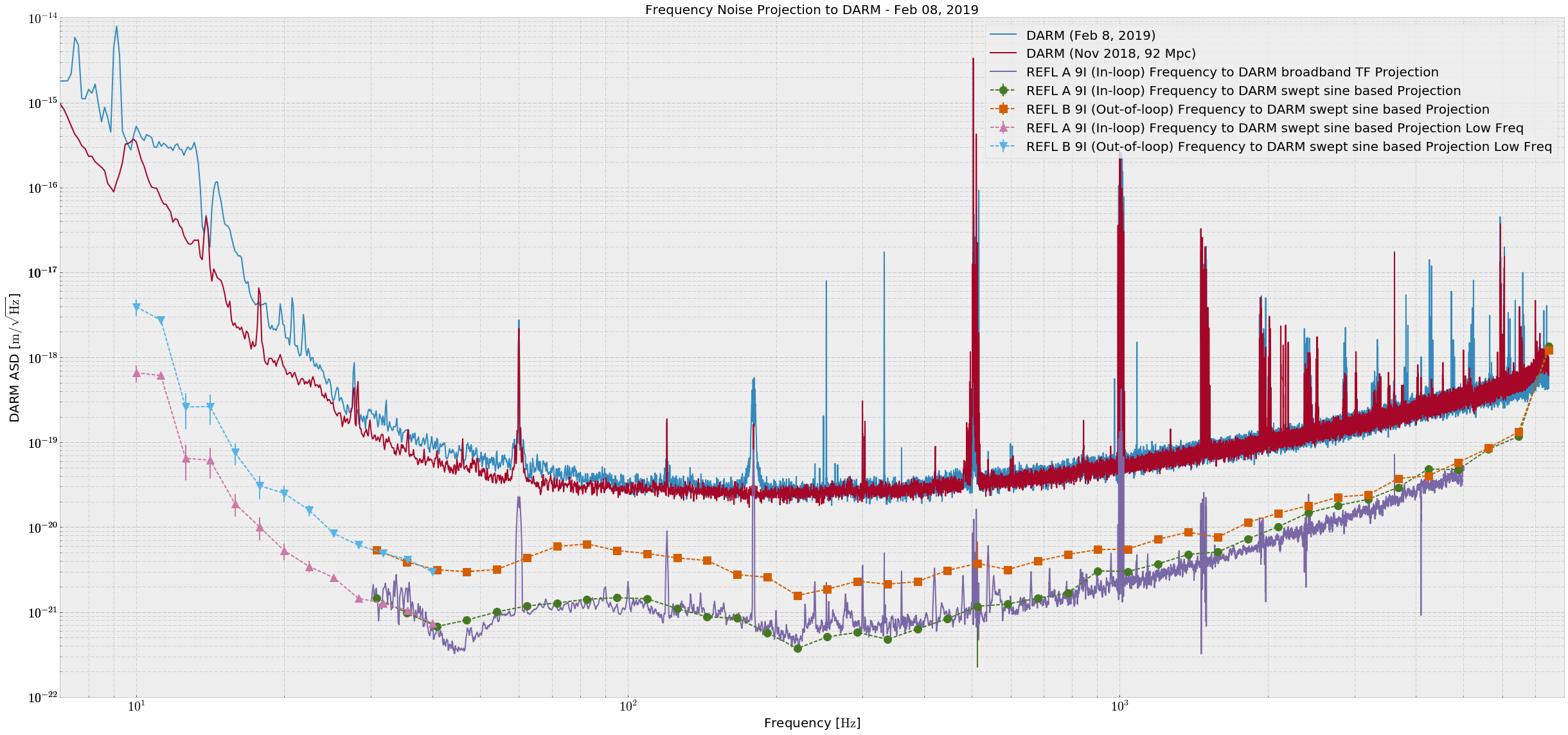
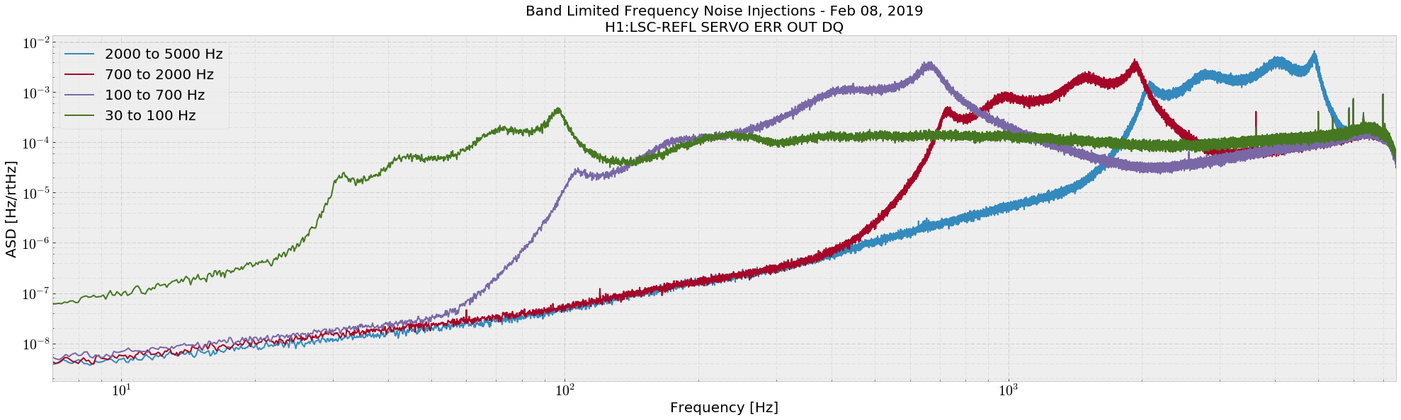
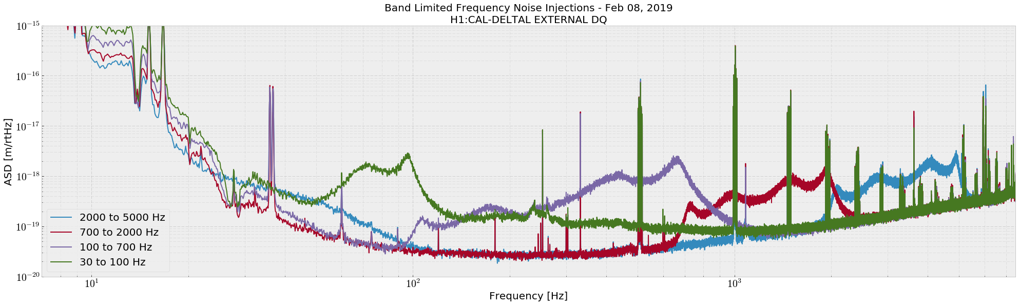
I projected frequency noise into DARM using the swept sine TF and broadband noise injection TF.

At 80 Hz we are a factor of 5 away from DARM with frequency noise, according to REFL B.  Otherwise we are not close except at very high frequencies.  (Attachment one)

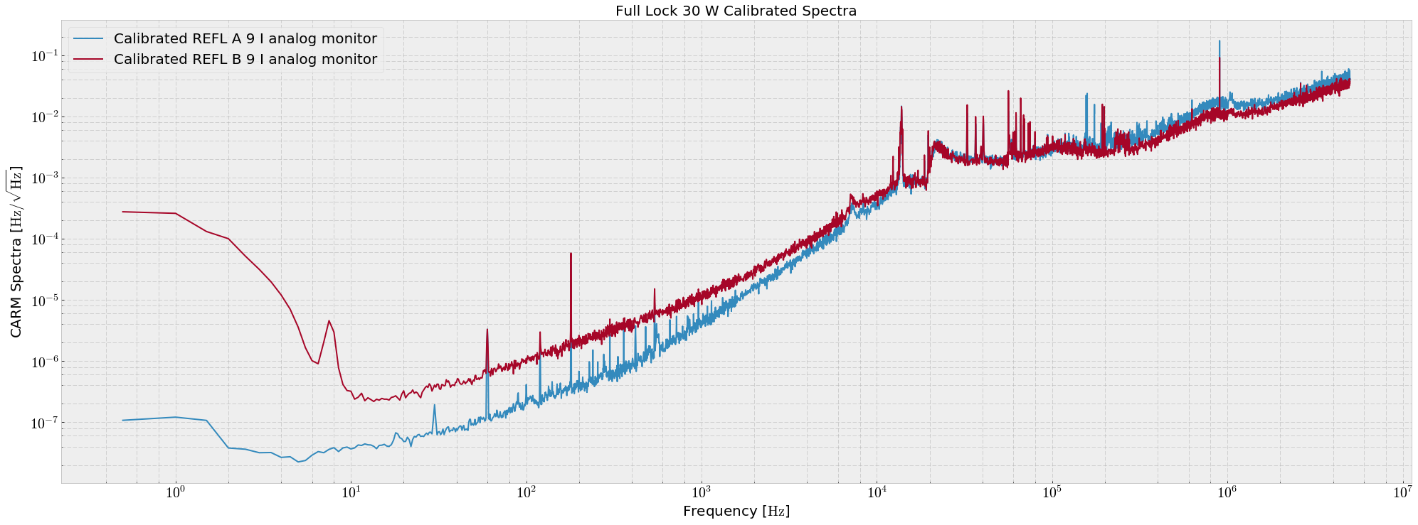
REFL B is the out of loop witness of frequency noise, and at low frequencies (below 2 kHz) this PD sees the shot noise on REFL A, the in-loop sensor.  The REFL spectra were taken directly out of the analog monitor of the demod boards, and calibrated with a CARM gain of ~ 10 mW/Hz, CARM pole of 0.85 Hz, and some REFL sensing chain TFs (Transimpedance A = 4900 Ω, (includes demod gain) Responsivity = e λ / (hc), Quantum Efficiency = 0.9)  (attachment four).  The calibration was not used for the projections.

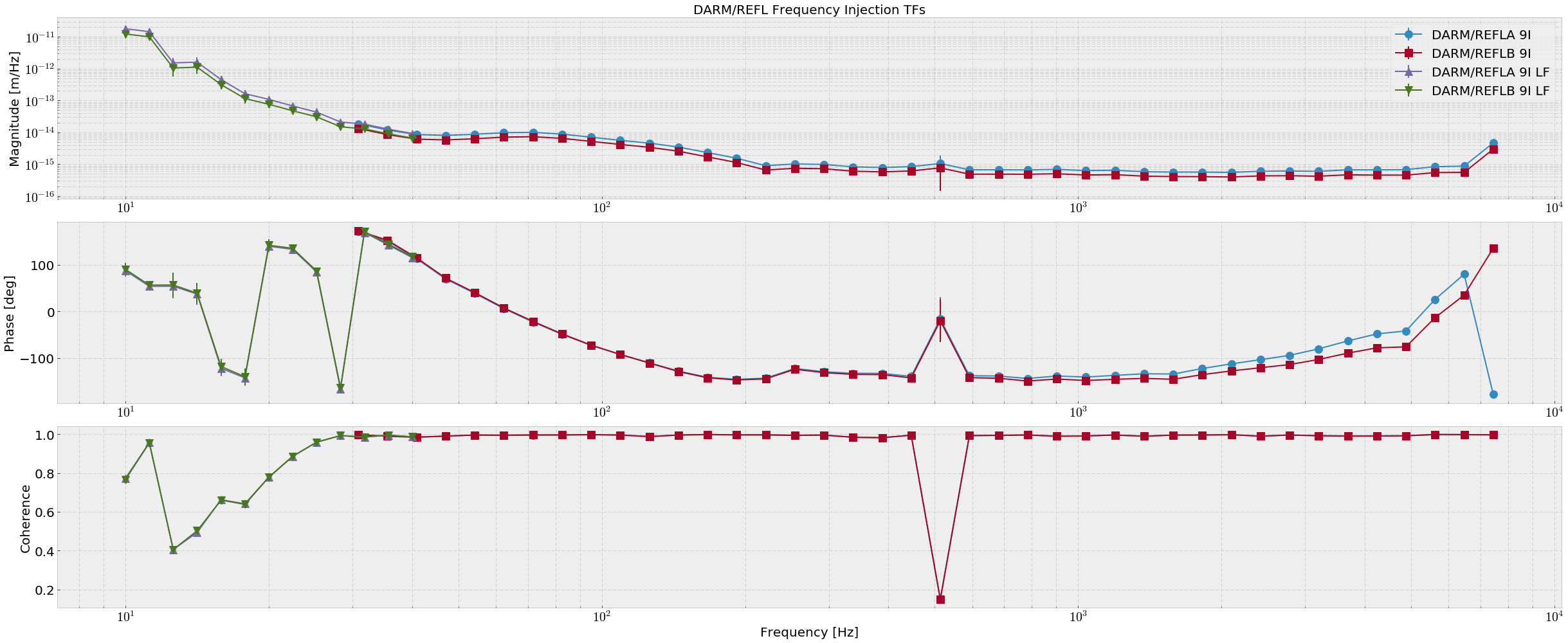
The swept sine TFs were measured from H1:LSC-REFL_{A,B}_RF9_I_ERR to H1:CAL-DELTAL_EXTERNAL_DQ (attachment two).  I have previously measured the conversions from the REFL analog pickoff IMON monitors to the digital REFL I ERR channels.  I have done this because H1:LSC-REFL_B_RF9_I_ERR is well calibrated into volts, but REFL A is not.
analog REFL A 9 IMON / H1:LSC-REFL_A_RF9_I_ERR = 7.87e-4   # V/cts
analog REFL B 9 IMON / H1:LSC-REFL_B_RF9_I_ERR = 1.02 # V/cts

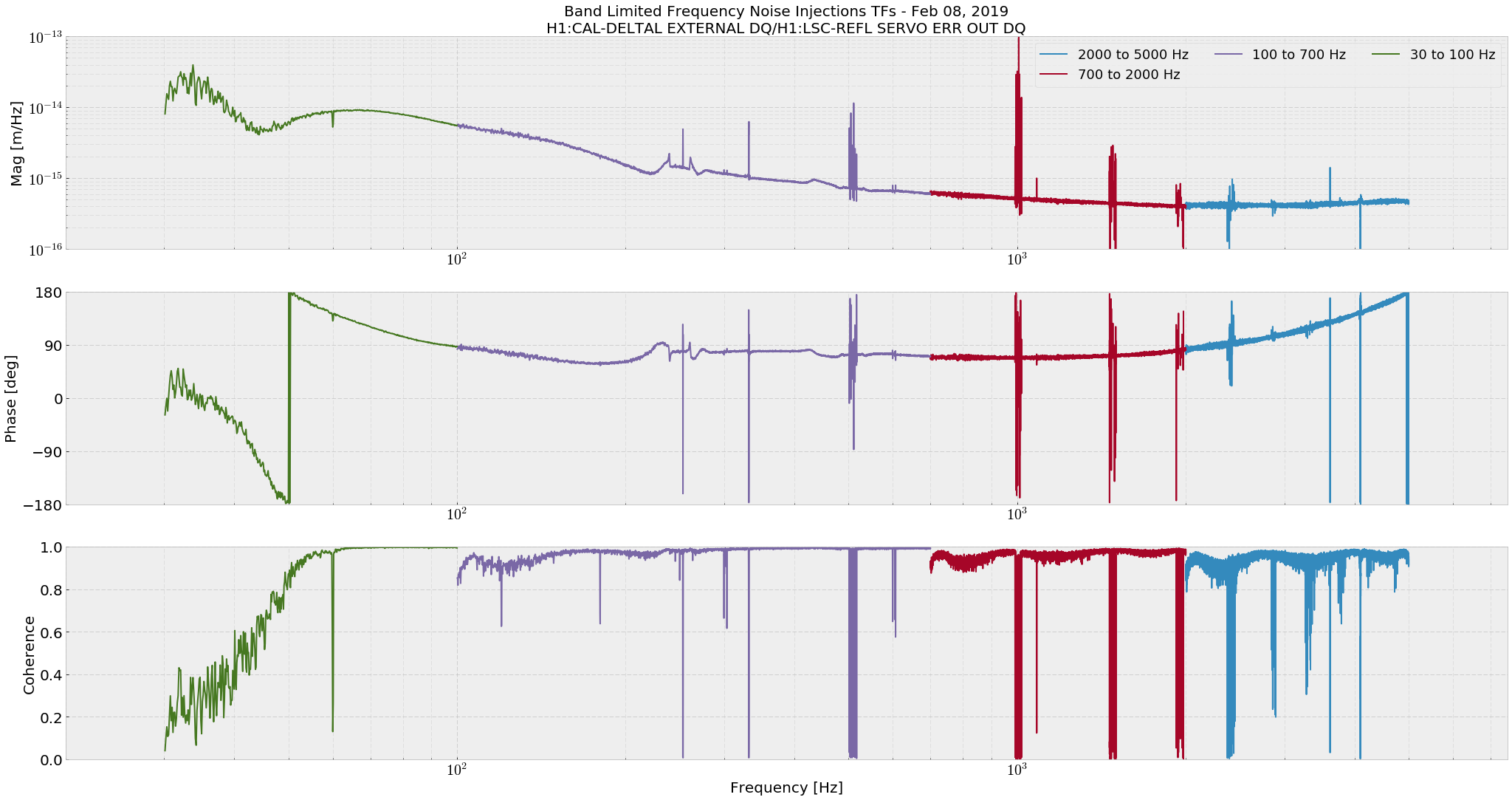
The broadband injection TF was estimated using H1:LSC-REFL_SERVO_ERR_OUT_DQ and H1:CAL-DELTAL_EXTERNAL_DQ (attachment three).  The only difference between H1:LSC-REFL_A_RF9_I_ERR and H1:LSC-REFL_SERVO_ERR_OUT_DQ is a factor of 13.1 dB of gain. 

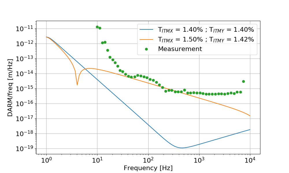
The increased laser frequency to DARM noise coupling we see at low-frequency likely follows from this arm power imbalance, and gives rise to the characteristic dip at around 45 Hz where the contrast defect and radiation pressure coupling mechanisms slightly cancel due to the phase difference.  Some modeling will be done to explain this curve.  
The high frequency flattening of the TFs is still not understood, explained colloquially by "carrier HOMs somewhere in the corner".  Anything in the arms would see the CARM and DARM poles and decay at high frequency, and previous tests show that the carrier is likely the main bearer of frequency noise witnessed by DARM at high frequencies.
Images attached to this report
Comments related to this report
gabriele.vajente@LIGO.ORG - 09:59, Friday 08 February 2019 (46867)

Here's a simulation of frequency noise to DARM coupling, based on the same parameters used before (46845, 46683). As for other couplings (PRCL to DARM for example), there is a discrepancy at low frequency, probably due to cross coupling through other LSC loops. And the high frequency flattening in the measurement is probably due to mismatch between the two arms (but in simulation, using the nominal RoCs and adding the ITM lenses do not change the result).


Images attached to this comment
H1 AOS
georgia.mansell@LIGO.ORG - posted 03:02, Friday 08 February 2019 (46863)
Moved PIT5 dither line back, and other locking notes

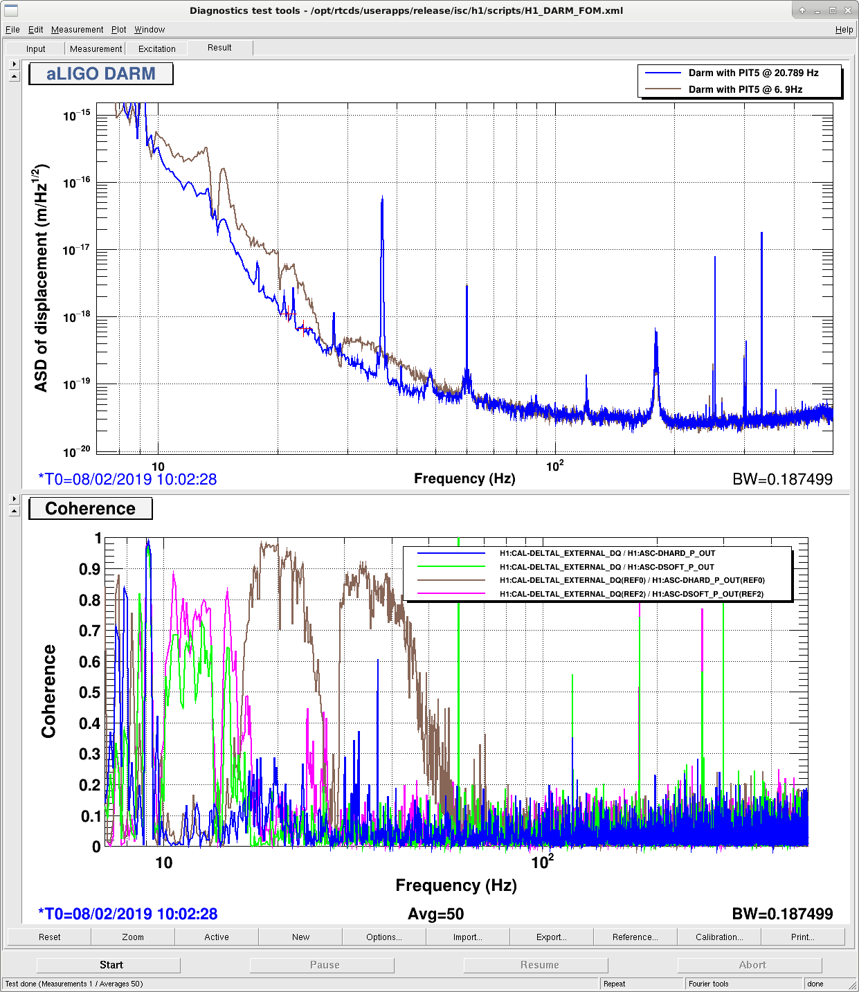
Dither line

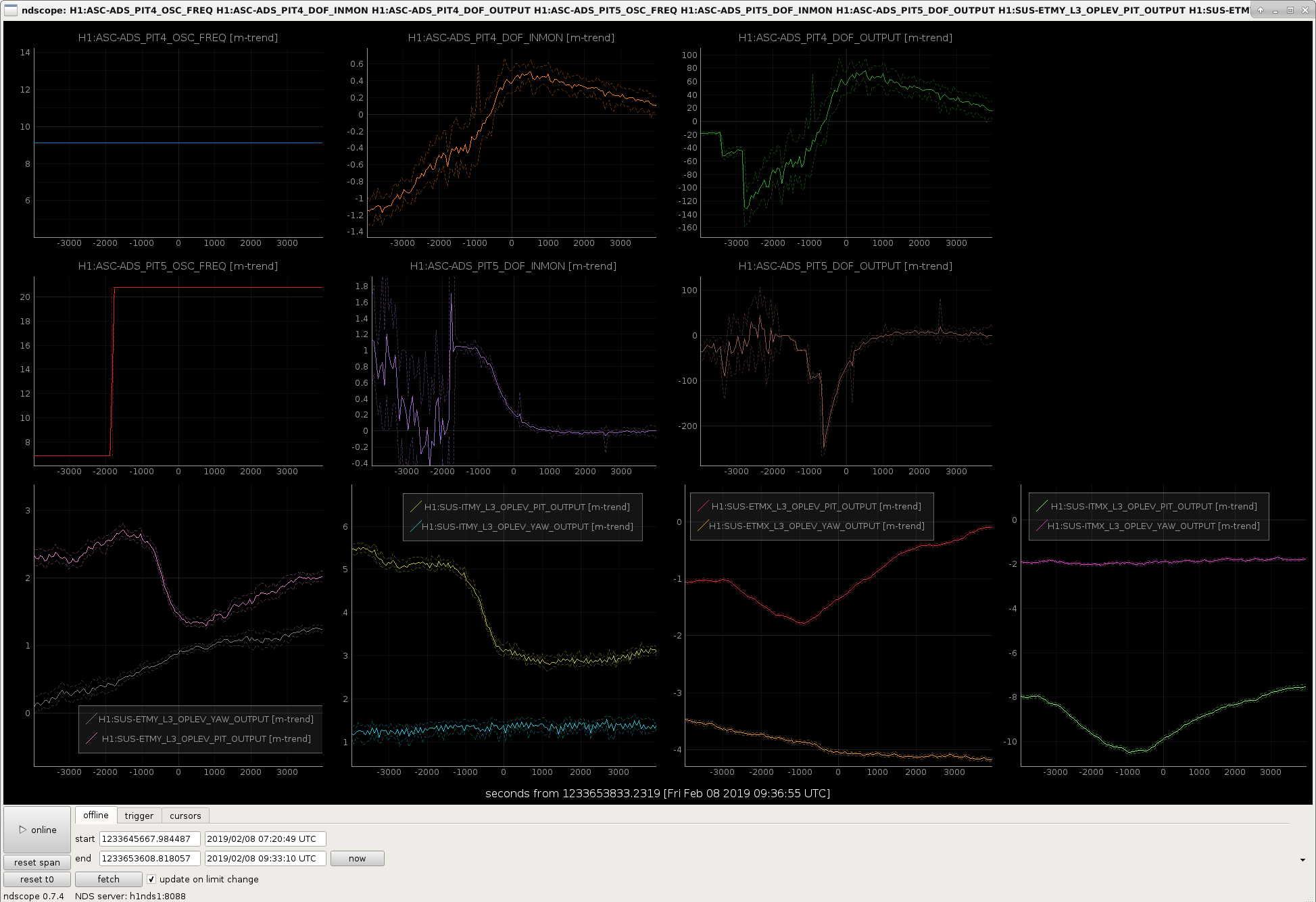
With lownoise_ASC back to a stable state, we had a chance to move another of the dither lines back to the 20Hz region (carrying on from last month). I moved PIT5, which controls the spot position on ETMY, back from 6.9 Hz to 20.789 Hz, and saw an improvement in DARM (first attachment). Still unclear why there is such a dependence on the dither line frequency. Second attachment is the time series of PIT4 (X arm) and PIT5 (Y arm) converging (in the case of PIT4 very very slowly) after I move the line. Bottom row is test mass op levs.

I reverted the settings in the guardian however tomorrow commissioners might want to pay attention in ENGAGE_SOFT_LOOPS and LOWNOISE_ASC and add extra gain if things are taking too long to converge.

180 Hz and OMC PZT3 out

With the new OMC PZT driver we've had a problem with a broad 180 Hz peak in DARM (third attachment shows a high-ish resolution spectrum taken between references). Currently while locking, the high voltage driver is sending a 10 V offset to PZT1 which is used to dither the length of the OMC. On Rich's suggestion I tried slowly adding an offset to this PZT (PZT3 in the OMC control screen), allowing the length change to be offloaded onto PZT2, and looked to see if the 180Hz peak changed. I got to 0V on PZT3, and saw no change in the 180 Hz noise.

Soft loop engagement

While acquiring lock earlier today we got stuck in engage_soft_loops. In the guardian we first turn on PIT3 and YAW3 which control the PRM pointing, and only engage the other loops once they're within a certain range, at one point today PIT4 (Xarm pitch) was not within that range. I used Hang's handy arm-slider-moving script to move the X soft P degree of freedom until it the dither error signal was close enough to be turned on. If this becomes a recurring problem we might need to loosen the convergence checker in guardian.

Images attached to this report
H1 ISC
marie.kasprzack@LIGO.ORG - posted 00:16, Friday 08 February 2019 (46862)
DSOFT P gain increase

Sheila, Georgia, Jenne, Marie

We modified the DSOFT P loop today:

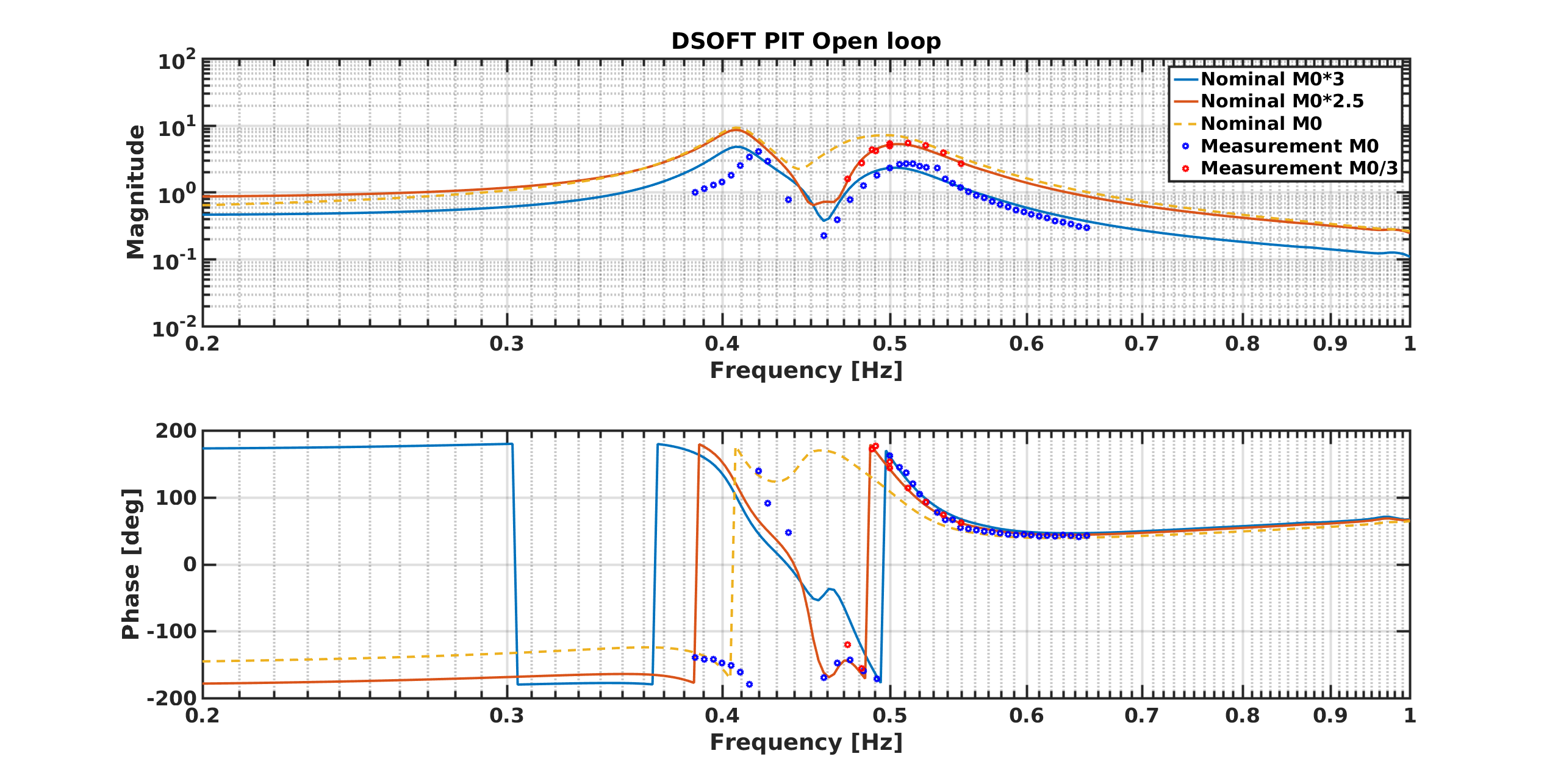
The measurement might be compatible with a reduction of the cross-over frequency, but the phase shift is small compared to what I expected (see figure 1). We might need to add a roll-off in M0 to further reduce the cross-coupling.

We lost lock tonight several times due to dtt excitation, but the good news is that we relocked fast each time to low noise without seeing any oscillation.The increase of DSOFT P gain is probably helping.

Images attached to this report
H1 INJ (INJ)
keith.riles@LIGO.ORG - posted 17:07, Thursday 07 February 2019 - last comment - 11:10, Friday 08 February 2019(46858)
CW injections restarted wth new actuation function
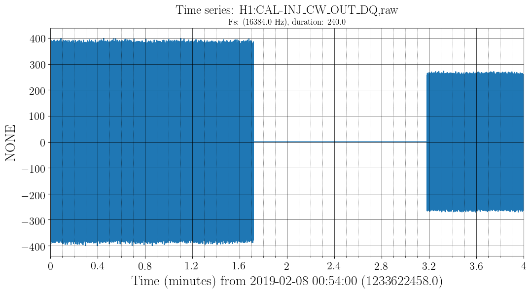
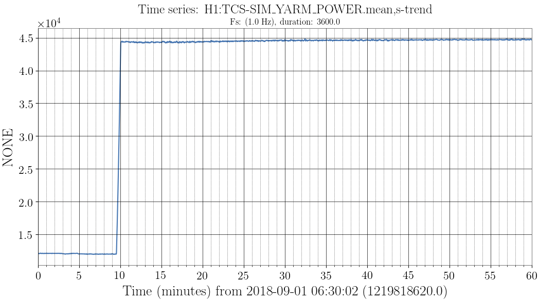
I have restarted the CW injections using the new actuation function that Evan posted here. The attached screen shot confirms the expected reduction in the envelope of H1:CAL-INJ_CW_OUT. The new injections are running as of GPS 1233622649 (Feb 08 2019 00:57:11 UTC).
Images attached to this report
Comments related to this report
keith.riles@LIGO.ORG - 08:20, Friday 08 February 2019 (46865)INJ
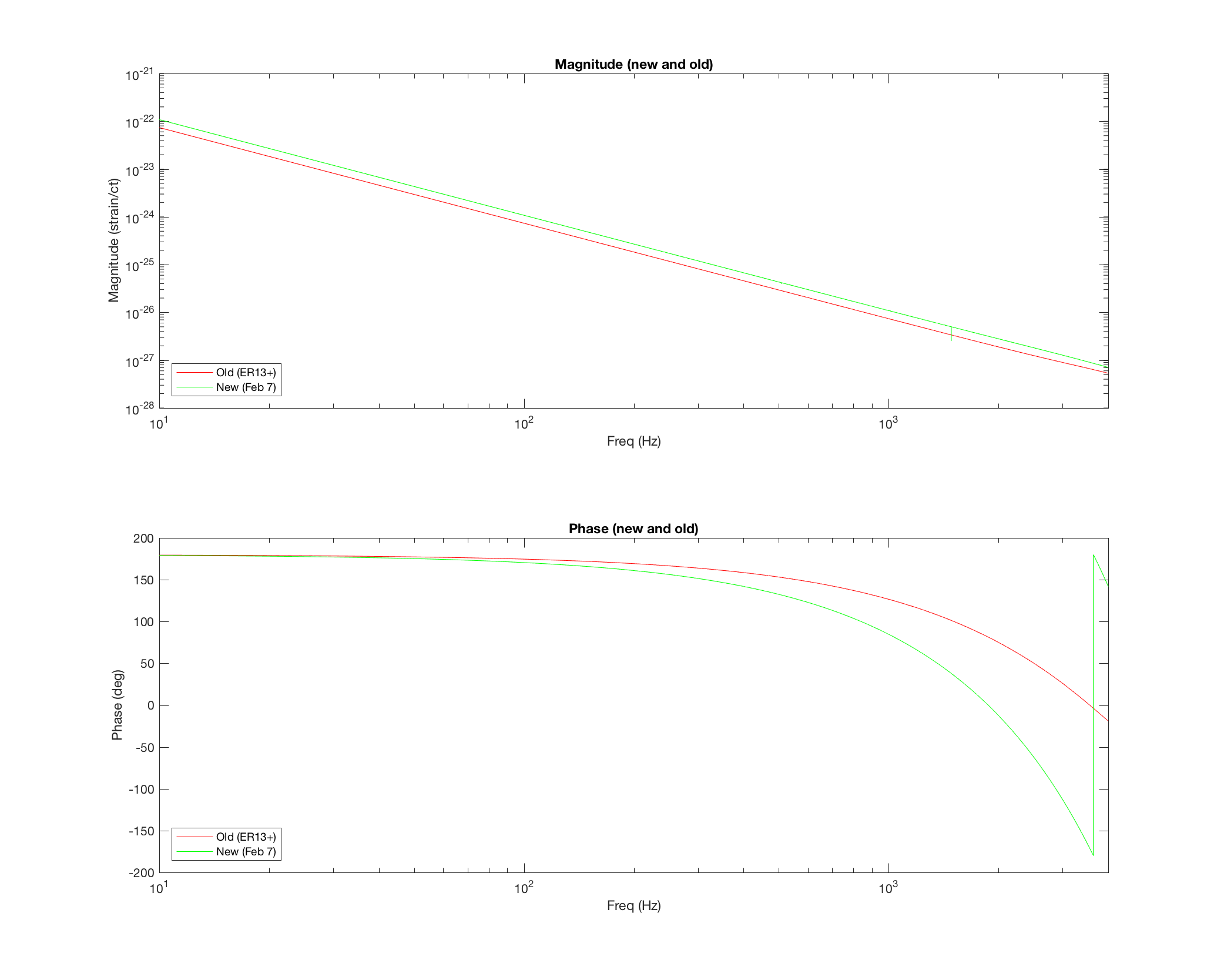
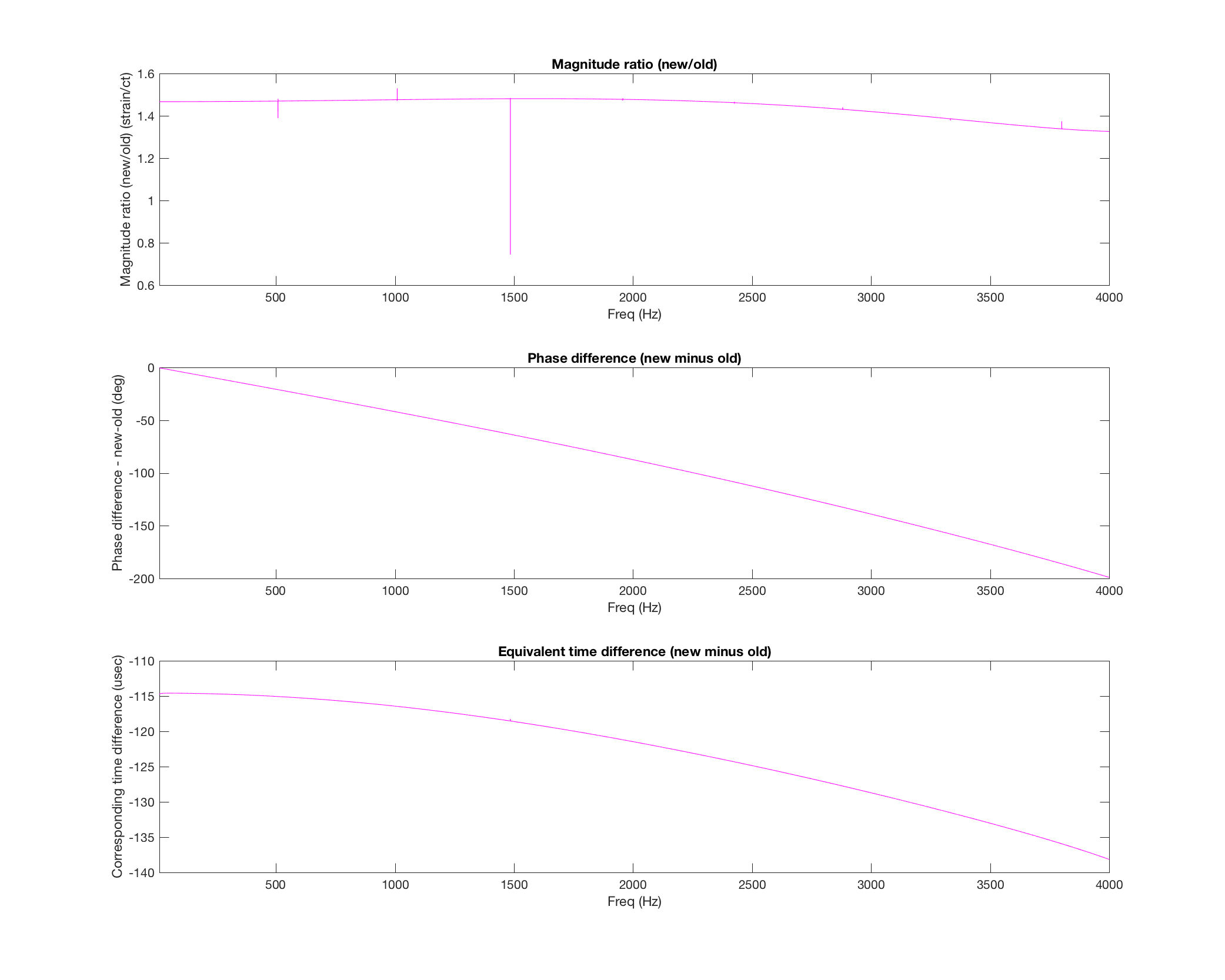
To understand what differences we should expect between previous and future CW injection recoveries, I have looked at differences between the actuation function used since ER13 and the one now in use. The attached graphs show the intended 1.47 magnitude rescale (near DC) and an additional time delay ranging from 115 usec at 10 Hz (low end of CW injections) and 138 usec at 4000 Hz.
Images attached to this comment
keith.riles@LIGO.ORG - 11:10, Friday 08 February 2019 (46869)INJ
Responding to an email query from Evan: The old actuation function used from ER13 until yesterday was the same one used in O2. Given the known 1-clock-cycle discrepancy in that run (discovered near the end of the run) and the additional 1-cycle delay from the new Guardian-driven actuation, we do expect to see a ~120 usec difference between these functions at low frequencies. Preliminary estimates from Jessica's injection monitoring suggest a ~130 usec discrepancy in recovery. So I think we're in good shape. We should know better in a week or so after accumulating more statistics.
H1 CAL (CAL, ISC, SUS)
jeffrey.kissel@LIGO.ORG - posted 16:42, Thursday 07 February 2019 (46854)
H1 SUS ETMX Driver Electronics Measurements Complete (Again; Different Method -- Less Information)
J. Kissel

In continued efforts to reduce the frequency-dependent systematic error in the actuation functions for each stage of ETMX (step ii in LHO:46806's "steps to [actuation function] success"), I've measured all three stages of the ETMX driver electronics using the remote infrastructure of monitor circuits, as was done for ETMY before O1 (see LHO:20846). 

As before, I have to use the secret functionality of the digital requests of the binary I/O switching -- requesting negative state numbers, which gives you control over the COILOUTF filters. This allows one turn off any existing digital compensation, and drive through all the COILOUTF banks simultaneously with DTT. The only difference from the previous attempt at this method: I remembered to set all gains in all COILOUTF for all quadrants to +1.0, so the data is not confused by magnet polarity compensation or gain balancing.

For the Jeff Kissel in 2023 when he has to make these kinds of measurements again, and doesn't want to drive to the end stations and use the mess of electronics -- you still have to:
Now -- although this method is much more convenient and fast, this method has the distinct problem for the coil drivers -- the fast current monitor (aka FAST I MON) circuitry pick offs are up-stream of the output impedance networks of the coil drivers, so one cannot fit and poles and zeros that impact the system's transfer function from that part of the driver (for the UIM driver, the network results in a simple pole-zero pair; for the PUM driver, network is complex and switchable, with a different set of poles and zeros between "on" vs. "off" of the switch). Thus, we're going to try to salvage what we can from the flawed Sunday measurements (LHO:46754), and stitch them together with today's data.

Fitting details and results to come, but the measurement templates live here:
/ligo/svncommon/CalSVN/aligocalibration/trunk/Common/Electronics/H1/Data/SUSElectronics/ETMX/
    UIM/2019-02-07/
        2019-02-07_H1SUSETMX_UIMDriver_WhiteNoise_0p1to7000Hz_State1_TF.xml
        2019-02-07_H1SUSETMX_UIMDriver_WhiteNoise_0p1to7000Hz_State2_TF.xml
        2019-02-07_H1SUSETMX_UIMDriver_WhiteNoise_0p1to7000Hz_State3_TF.xml
        2019-02-07_H1SUSETMX_UIMDriver_WhiteNoise_0p1to7000Hz_State4_TF.xml

    PUM/2019-02-07/
        2019-02-07_H1SUSETMX_PUMDriver_SweptSine_0p01to30_State1_TF.xml
        2019-02-07_H1SUSETMX_PUMDriver_SweptSine_0p01to30_State2_TF.xml
        2019-02-07_H1SUSETMX_PUMDriver_SweptSine_0p01to30_State3_TF.xml
        2019-02-07_H1SUSETMX_PUMDriver_SweptSine_0p01to30_State4_TF.xml
        2019-02-07_H1SUSETMX_PUMDriver_WhiteNoise_1to7000Hz_State1_TF.xml
        2019-02-07_H1SUSETMX_PUMDriver_WhiteNoise_1to7000Hz_State2_TF.xml
        2019-02-07_H1SUSETMX_PUMDriver_WhiteNoise_1to7000Hz_State3_TF.xml
        2019-02-07_H1SUSETMX_PUMDriver_WhiteNoise_1to7000Hz_State4_TF.xml

    TST/2019-02-07/
        2019-02-07_H1SUSETMX_ESDLVLNDriver_WhiteNoise_0p1to7000Hz_State1_TF.xml
        2019-02-07_H1SUSETMX_ESDLVLNDriver_WhiteNoise_0p1to7000Hz_State2_TF.xml

As we begin to fit, we're finding that the broad-band excitations are a little lacking in low-frequency data points (and wasting high frequency data points), resulting in a ~3% systematic error in magnitude. Too big! In the future, I may suggest we do as we did for the PUM driver and use a swept sine excitation, and sadly go beyond 0.1 Hz down to 0.05 Hz. 
H1 TCS (TCS)
aidan.brooks@LIGO.ORG - posted 16:35, Thursday 07 February 2019 (46856)
ETMY absorption (probably) not correctly measured

I've been attempting to create a repository of all the self-heating wavefront maps measured with the HWS and I reviewed each of the 8 test masses. Some of the measurements are much cleaner than others.

In particular, I discovered that the ETMY HWS is somehow not functioning correctly as it shows a negative thermal lens associated with the interferometer powering up which would imply negative absorption. This is clearly non-physical as it probably violates several laws of thermodynamics. My suspicion is that the mode-matching on the source beam needs to be improved (difficult with the multi-mode fibers we need to use to get the required intensity). We will investigate further. 

https://ldas-jobs.ligo.caltech.edu/~aidan.brooks/

Images attached to this report
Non-image files attached to this report
H1 SEI
jim.warner@LIGO.ORG - posted 16:20, Thursday 07 February 2019 (46857)
Corner Station Sensor correction switched to HAM5 STS

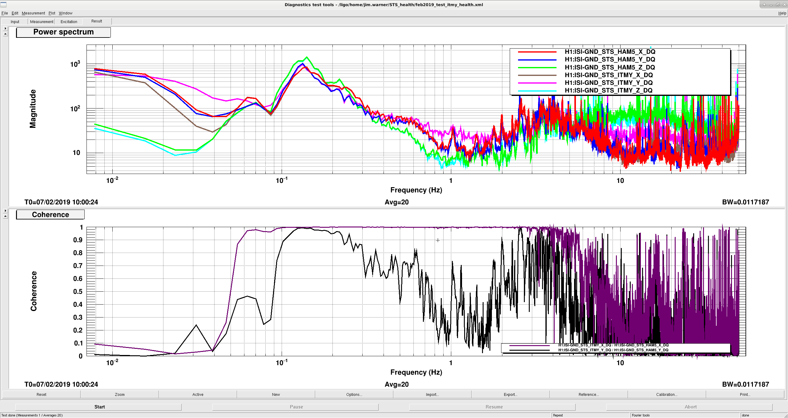
Arnaud and I noticed last week that some of the ISIs were moving differently in their beam axis directions in the corner. Looking more closely this week it looks like the ITMY STS has some extra noise on its Y-axis. Fortunately, Hugh had moved the HAM5 seismometer near the biergarten long ago, looking for a lower tilt location, so I have switched all the corner station chambers to use this instrument instead.

Attached plot shows asds for the ITMY and HAM5 STS, they should agree up to several hz, but the ITMY sensor shows extra noise around 1 hz in Y. The bottom plot shows the coherence between the two sensors, X coherence is very good, but the Y coherence is not so good. I've also looked at the coherence to the ITM HEPI L4Cs, and the story that the HAM5 sensor is better hangs together.

Somebody said something about T360s? Can I have one please?

Images attached to this report
H1 General
jim.warner@LIGO.ORG - posted 16:11, Thursday 07 February 2019 (46850)
Shift Summary

18:00 Kyle to MY

19:15 Karen to MY

21:30 DickG to CER

21:30 TJ, Danny to TCSY

22:15 RAbbot and Dean to HAM6

22:15 Robert to LVEA


LHO VE
kyle.ryan@LIGO.ORG - posted 15:58, Thursday 07 February 2019 (46855)
Tested rebuilt ion pump (s/n #70115) at Y-mid

Gerardo M., Kyle R.

Today we uncrated and tested the newly rebuilt ion pump that is intended to replace the iLIGO IP9 at the Y-mid station.  Both internal pumps (A and B), seemed to work and behave normally - for the most part.  It did seem to take longer for it to reach a steady current (4.7 uA) than the previous pumps and may not be as low of current(?)  Additionally, both 1.33 CFF flanges for the HV feedthroughs were noticeably "gappy".  We will leak test these prior to installation (anticipated to be Tuesday, February, 12th). 

Disregard the indicated pressure in the picture as it doesn't apply to this size of pump.  The indicated current is valid. 

Non-image files attached to this report
H1 CAL (CAL, DetChar, INJ)
aaron.viets@LIGO.ORG - posted 15:24, Thursday 07 February 2019 (46853)
GDS calibration pipeline restarted with updated configuration

[M. Wade, A. Viets, J. Rollins, T. Massinger]

I restarted the primary and redundant h(t) pipelines around GPS time 1233614282.  This restart picked up new filters and configurations.  The new filters file is identical to this one except that it makes the pipeline use the actuation pcal line (fpc1 = 17.9 Hz) instead fpc4 = 7.93 Hz to compute the frequecy fs and quality factor Q of the optical antispring of the signal recycling cavity.

The configuration changes are the following:

H1 PSL (PSL)
peter.king@LIGO.ORG - posted 07:21, Thursday 07 February 2019 - last comment - 18:49, Friday 08 February 2019(46841)
Reference cavity alignment tweak
Tweaked the alignment into the reference cavity.  Transmission went from ~1.3 to 4.1.

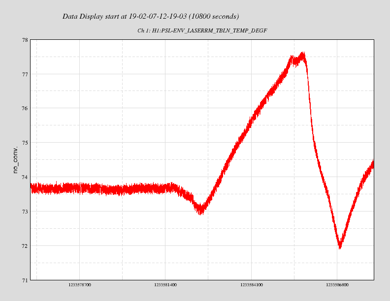
    whilst I was in the enclosure, the HEPA fans and AC tripped off.  Don't know why.  As a
result it may take the temperature inside the enclosure a while to settle.  The pre-modecleaner
heater drive voltage nearing zero was the tell-tale sign that gave it away.

    Attached is a plot of the room temperature around the time of the mishap.
Images attached to this report
Comments related to this report
rana.adhikari@LIGO.ORG - 17:59, Thursday 07 February 2019 (46860)PSL

is there a new FSS loop measurement to go with this increased cavity power (and increased optical gain)?

rana.adhikari@LIGO.ORG - 18:49, Friday 08 February 2019 (46882)

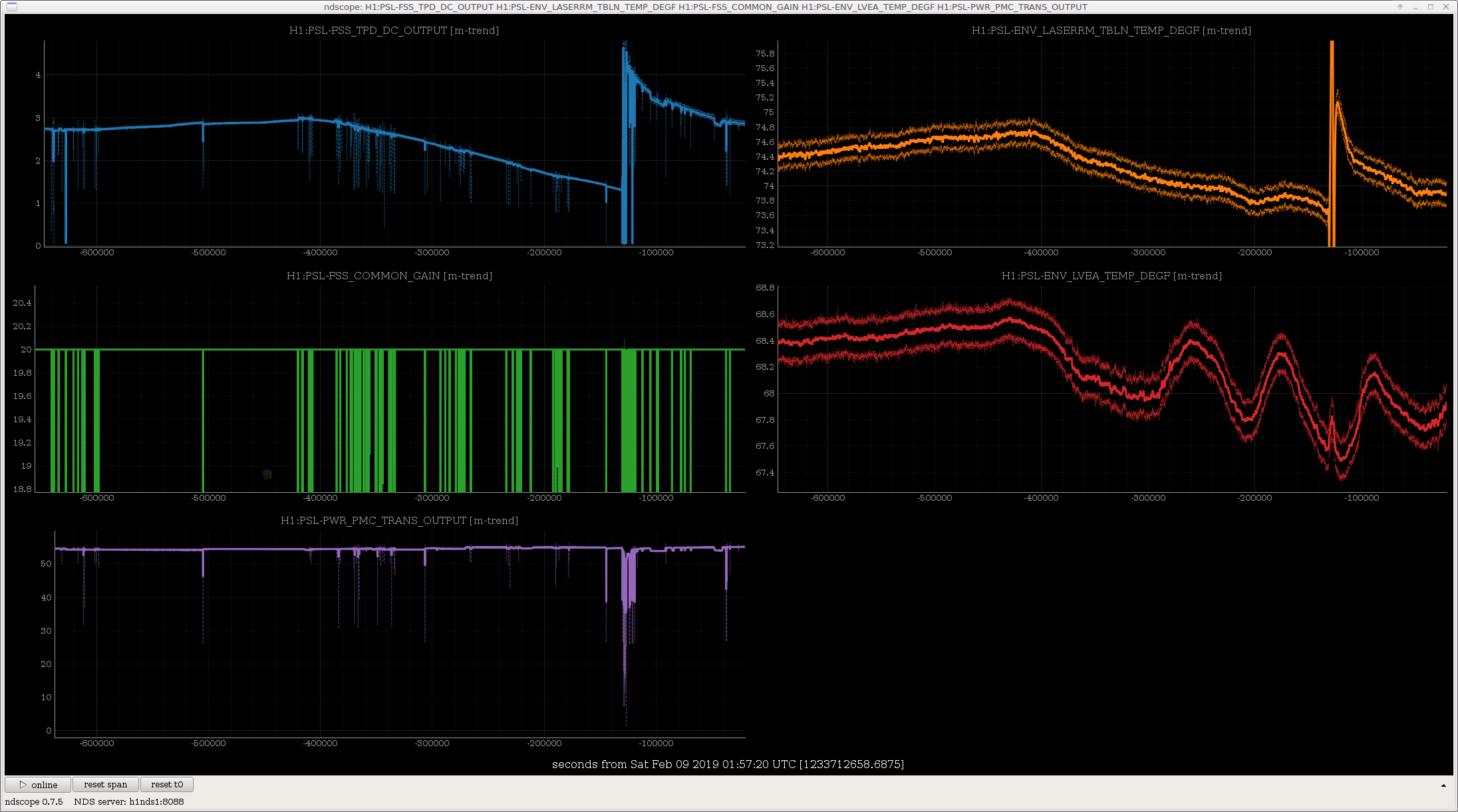
as I suspected, the FSS Common gain has not been adjusted to follow the drifting ref cav transmission, so the FSS UGF has been all over the map. Presumably, the transmitted light, which is used for ALS, is also changing by this large factor.

There is something in the reference cavity optical path which drifts way too much. A 1 degF change in the table temperature is making a 2x change in the cavity power.

You can see that Peter's tweak up happens with the temperature high and so the power degrades again as soon as he leaves the PSL and the temperature changes.

The PMC, on the other hand, has almost no temperature dependence to its transmission.

Options:

  1. Take a couple weeks to diagnose what is wrong with the optical mounts in the refcav path.
  2. Block the beam to the refcav/FSS as LLO and 40m have done.
  3. Redesign the FSS & IMC loops to be stable with 3x gain fluctuations.
Images attached to this comment
H1 SYS (CAL, GRD, INJ, ISC)
jameson.rollins@LIGO.ORG - posted 14:47, Tuesday 15 January 2019 - last comment - 15:11, Thursday 07 February 2019(46428)
initail ODC removal work

ODC removal (as per ECR 12045) has begun.  Summary:

Detailed front end changes:

Further removal of ODC from the rest of the system (ISC, SUS, PEM, etc.) is deferred to later maintenance. 

Comments related to this report
keita.kawabe@LIGO.ORG - 17:17, Tuesday 15 January 2019 (46447)

Following models were changed to remove ODC completely and compiled but not installed. Deferred to another opportunity.

h1ascimc (1 IPC sender (PCIE) and an entire ODC block were removed, doesn't use the library, one less fast channel on the frame)

h1pslpmc (1 sender (SHMEM) as well as an entire ODC block was removed from h1 model, ODC-related things were purged from the library, no change in fast channels)

p1psliss (2 receivers (SHMEM) for FSS and PMC as well as two ODC blocks were removed from h1 model, ODC-related things were purged from the library, one less fast channel on the frame)

h1pslfss (1 sender (SHMEM) as well as an ODC block were removed from h1 model, ODC-related things were purged from the library,  no change in fast channels)

h1tcscs (1 sender (SHMEM) as well as an ODC block were removed from h1 model, ODC-related things were purged from the library, one less fast channel on the frame)

h1iscex (done by Jamie, no change in fast channels)

h1alsex (1 sender (SHMEM) as well as an ODC block were removed from h1 model, doesn't use library, one less fast channel on the frame)

h1alsey (1 sender (SHMEM) as well as an ODC block were removed from h1 model, doesn't use library, one less fast channel on the frame)

h1lsc (1 sender (PCIE) and an ODC block are removed from the h1 model, doesn't use library, one less fast channel on the frame)

h1omc (1 sender (PCIE) as well as an ODC block were removed from h1 model, ODC-related things were purged from the library, one less fast channel on the frame)

h1pemex (1 sender (SHMEM) as well as an ODC block were removed from h1 model, doesn't use library, no change in fast channels)

h1pemey (1 sender (SHMEM) as well as an ODC block were removed from h1 model, doesn't use library, no change in fast channels)

all SEI models at the end stations (done by JeffK)

Following models are yet to be changed.

all sus models (TBD by JeffK)

keita.kawabe@LIGO.ORG - 13:17, Tuesday 22 January 2019 (46576)CDS, DetChar, SYS

Update on Jan 22

During the maintenance on Jan22, the following models without ODC were installed.

h1lsc, h1ascimc, h1omc, h1iscex, h1alsex, h1alsey, h1tcscs, h1pemex, h1pemey.

(h1asc was updated and installed for something unrelated to ODC.)

Remaining frontends that are yet to be replaced with new ones without ODC:

All SUS (models are yet to be changed/compiled).

All end station SEI (models are ready).

h1pslpmc, h1pslfss, h1psliss (models are ready).

Remaining frontends that will be changed again after new HW injection infrastructure is confirmed to work by transient injection group(s):

h1calex (model is yet to be done, PINJX will be completely removed).

h1odcmaster itself (this will be retired).


keita.kawabe@LIGO.ORG - 14:35, Monday 04 February 2019 (46769)

Update Feb/04/2019

All SUS models were modified to remove ODC, compiled successfully, but not installed. These are:

h1susetmx, h1susetmy, h1susitmx, h1susitmy, h1susbs, h1suspr3, h1suspr2, h1susprm, h1sussr3, h1sussr2, h1sussrm, h1susmc1, h1susmc2, h1susmc3, h1susomc, h1susopo, h1susim (and h1sustmsx and tmsy and h1sushtts on Feb/05/2019)

One PCIE IPC sender and one fast channel were removed per each model, as well as many EPICS channels. One new EPICS channel (ODCCHAN_PLACEHOLDER) was added per each model.

Library parts (QUAD_MASTER, QUAD_ITM_MASTER, BSFM_MASTER, HSTS_MASTER, HLTS_MASTER, OMCS_MASTER, OPOS_MASTER) are still compatible with old models, so if you want to compile any of old sus models with the new library you can. In that case ODC IPC will be plugged to zero.

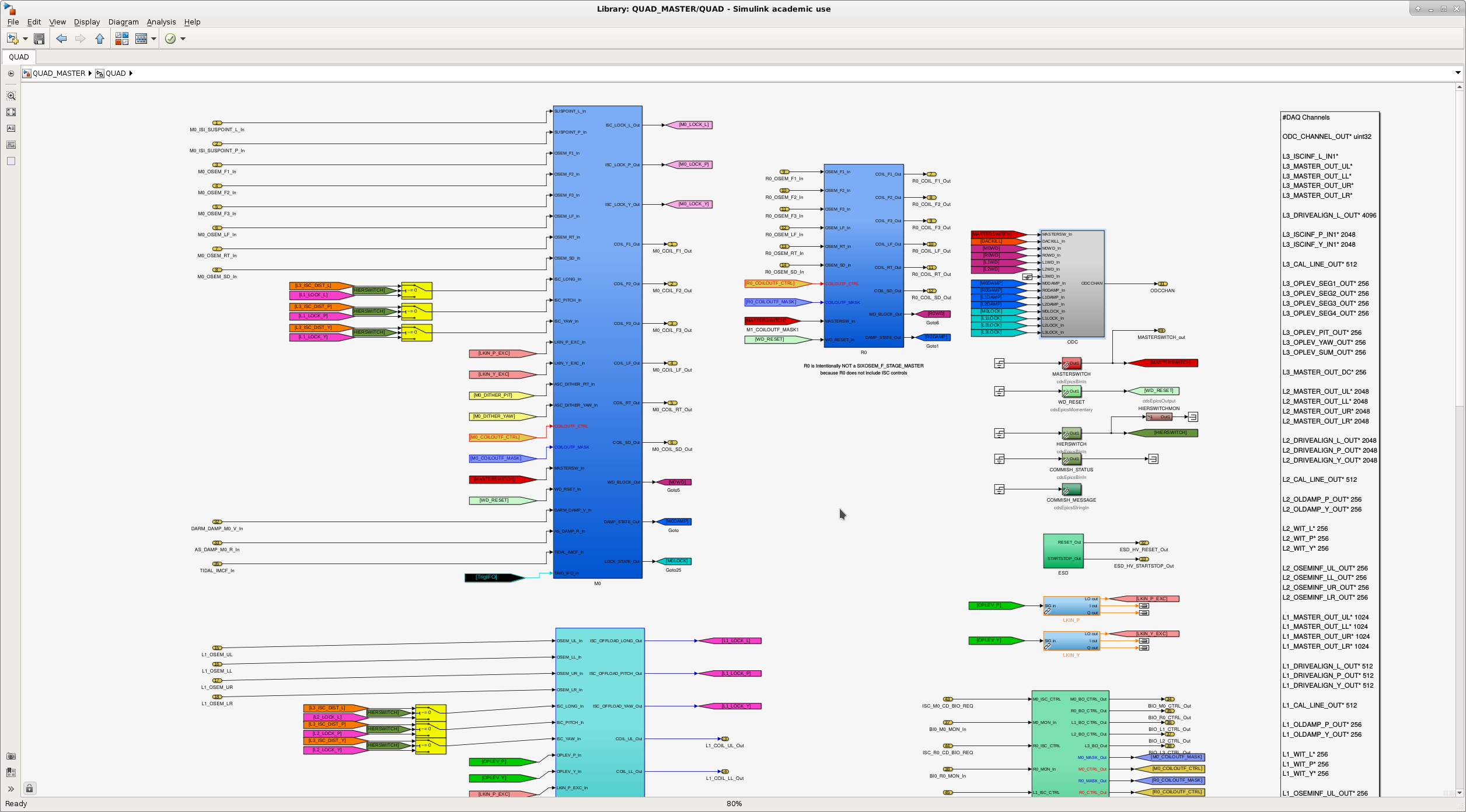
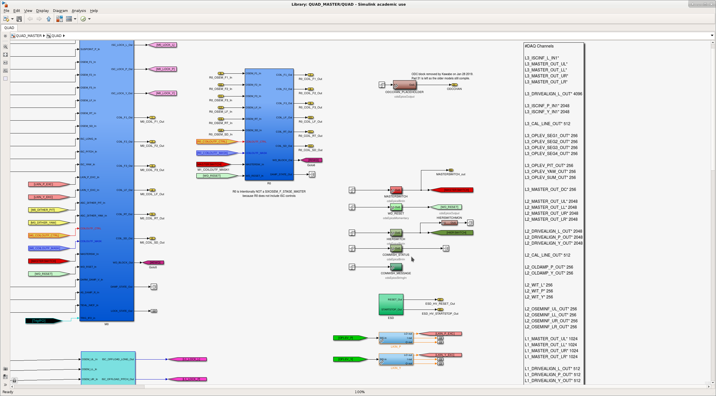
Attached are typical before/after view of the library parts.

Images attached to this comment
keita.kawabe@LIGO.ORG - 16:38, Tuesday 05 February 2019 (46803)

Boo. I just assumed that MC1, MC2 and MC3 all use HSTS_MASTER library part, but MC2 actually uses MC_MASTER part. I only edited HSTS_MASTER and individual model (h1susmc1, 2, 3).

As a result, ODC was not completely removed out of h1susmc2. This is going to be fixed in the next opportunity.

rahul.kumar@LIGO.ORG - 15:11, Thursday 07 February 2019 (46852)CDS, SUS
Keita and Rahul

Keita showed me how to make changes to the front end model of SUS. We made changes to MC_MASTER library parts to remove ODC. We complied h1susmc2 successfully, however we didn't install it. 
Displaying reports 43161-43180 of 88637.Go to page Start 2155 2156 2157 2158 2159 2160 2161 2162 2163 End