Daniel, Nutsinee
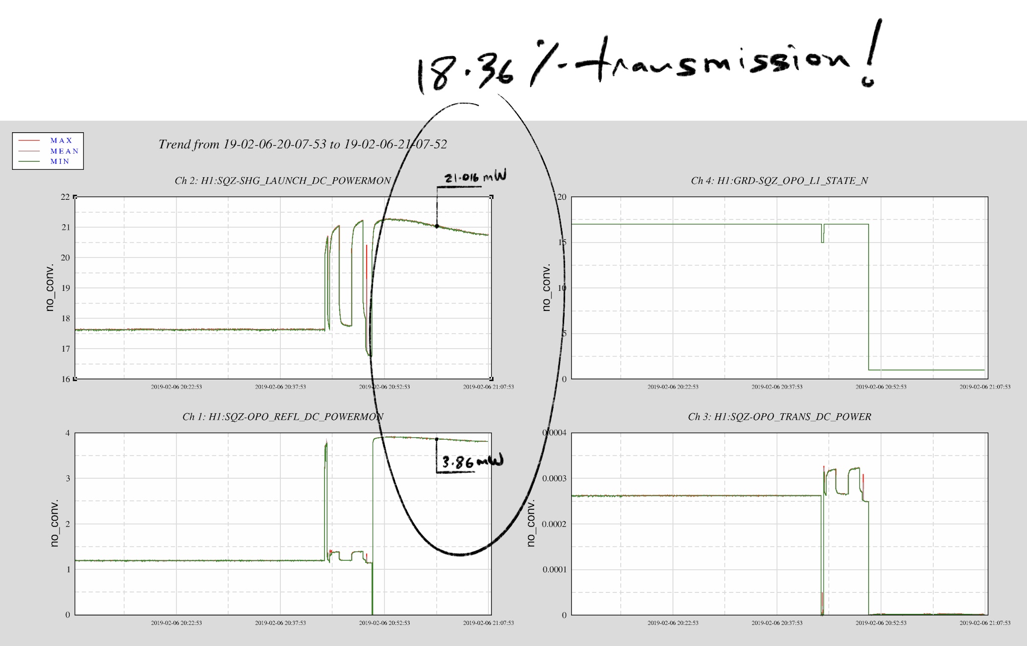
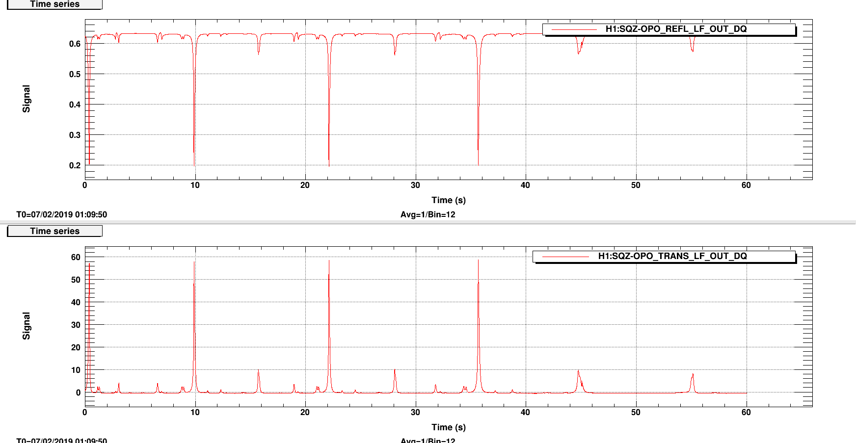
Today we saw the most green transmission we haven't seen in awhile. As of today we are back to 18% transmission (we have been at 13% transmission since beginning of January). Here's a plot looking at OPO REFL when OPO was unlocked and totally off-resonance.

This bizarre behavior happened very suddenly, today morning at 8:14 local was the clearest turning point. The intensity servo tried to engage but hit the limit because the set point was too far off from the actual OPO refl power.

Looking at the OPO scan it seems like TEM10 has just disappeared compared to alog46474. We now have 83% mode matched (was 78% back in January).
It appears that we have a self-align OPO cavity. I'll take that.
This is rather starting to sound like SBS (speculated as so by B. Lantz on the SYS fiber call). Im not sure of another mechanism that could move the modes like this over such a short timeperiod. Possibly a 01 acoustic mode pulling energy out of the 00 and moving it slighly into 01, while generating a reverse propagating stokes 01??
If/when it goes back to the lossy state, can you look at the retro-reflection from the fiber from your power monitor pickoff mirror?
Tweaked the alignment into the reference cavity. Transmission went from ~1.3 to 4.1.
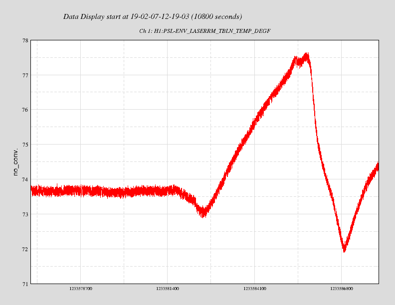
whilst I was in the enclosure, the HEPA fans and AC tripped off. Don't know why. As a
result it may take the temperature inside the enclosure a while to settle. The pre-modecleaner
heater drive voltage nearing zero was the tell-tale sign that gave it away.
Attached is a plot of the room temperature around the time of the mishap.
is there a new FSS loop measurement to go with this increased cavity power (and increased optical gain)?
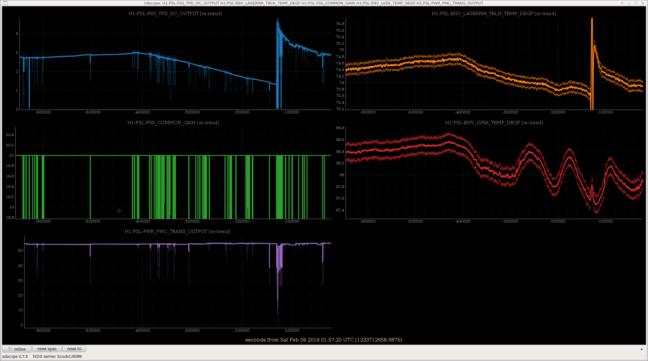
as I suspected, the FSS Common gain has not been adjusted to follow the drifting ref cav transmission, so the FSS UGF has been all over the map. Presumably, the transmitted light, which is used for ALS, is also changing by this large factor.
There is something in the reference cavity optical path which drifts way too much. A 1 degF change in the table temperature is making a 2x change in the cavity power.
You can see that Peter's tweak up happens with the temperature high and so the power degrades again as soon as he leaves the PSL and the temperature changes.
The PMC, on the other hand, has almost no temperature dependence to its transmission.
Options:
Filiberto, Dean, Daniel, Rich More to follow, but today we reversed the installation of the recently modified OMC Piezo Driver. Removing the driver fixed the broad 180Hz peak in DARM. There was a suspicion that the installation of the modified chassis was causing an increase in a broad peak in DARM (about 50Hz wide at 180Hz center). Initially, we terminated the inputs of the newly installed chassis, and removed the monitor readback cables used to monitor the newly enabled bias function (the possibility existed that there was a ground loop associated with the monitor cable). None of these attempts seemed to remedy the broad noise around 180Hz. We even speculated that the increased dither associated with the change to the new system may have manifested in an increase in the 180Hz component, but after reverting to the old chassis and observing a "normal" 180Hz component with the OMC locked, we increased the dither to see if the broad 180Hz noise came back, but it didn't. At this point, we must conclude that there is some aspect of the newly modified approach that causes an unfortunate addition of noise at 180Hz. There is a possibility that the observed noise may be related to the change in the source impedance associated with driving the second piezo with the new HV driver board. With this in mind, we have prepared an inline circuit that will emulate the output impedance of the new HV driver. We plan to insert this circuit tomorrow as a test. This device may yield insight into whether the addition of the second HV driver causes some form of environmental pickup in the wiring leading to the OMC that manifests in a broad 180Hz peak.
Thinking about this more, I suppose it is possible that by adding the second HV board to the OMC cavity, there might exist a greater susceptibility to power supply noise due to the low voltage (10VDC) that the second HV board's quiescent operating point was set to. In other words, it may be close to a rail, and the feedback loop has diminishing gain due to the circuit configuration, which might lead to higher power line harmonic susceptibility. I will check this on the newly constructed OMC driver. A simple mitigation if this is the case, would have been to command the second HV (the biasing amp) to a higher voltage away from the 0V lower rail. More to follow later, as this still seems like a priority to understand in terms of electronics.
The figure shows that there were a few small peaks in DARM during last night’s squeezing that were coherent with an accelerometer at ISCT6.
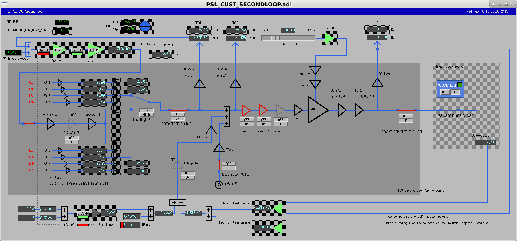
After the intensity projection yesterday Daniel asked me to look at the ISS OLG. Gabriele showed me how to take the analog ISS OLG measurements. We seem to be marginally stable (7 degrees phase margin) with the ISS loop where we nominally sit (OLG in attachment one, ISS Secondloop nominal medm screen in attachment two). Nominally, H1:PSL-ISS_SECONDLOOP_GAIN = 0 dB, and this is how I took the first measurement, the dark blue line in the plot. I increased the ISS SECONDLOOP GAIN by 6 dB (light blue), and then another 6 dB (orange). This gave us an additional 30 degrees of phase margin. The gain seems to not want to increase more, so I didn't push it past +12 dB. Looking at the ISS to DARM coherence at HF, it seems to be reduced from 0.5 to 0.2 now. This is good, but still needs to be reduced further if we are going to reap the benefits of squeezing.
The ISS second loop UGF used to be higher than this, right in the middle of the phase bubble.
See for example 45185
Increasing this gain needs some more thought. We failed to Increase_Power due to an ISS instability.
For now, we've just decreased the VGA gain slider back to 0dB, and are able to lock.
Sheila, Gabriele and I tried increasing the VGA gain by 1dB and decreasing the slow offset feedforward path by 1dB (with the goal of slowly stepping toward the 12dB that Craig used last night), but even that 1dB step made the ISS diffracted power go crazy. We'll need to relook at this in an IMC-only configuration.
Since the low ISS second loop gain is a problem for high frequency noise, but not at all a problem for locking stability or low frequency sensitivity, we're leaving it as it used to be for now.
We were stable at POWER_30W for a while, then we tried to go to LOWNOISE_ASC. A pitch instability rang up. I could fix it by changing DHARD_P gain from -42 to -60 and CHARD_P from 0.6 to 1.
I suspect CHARD is the culprit, since we changed the blend filter for the QPDs reducing the gain by 10 dB.
I did not put the CHARD and DHARD changes in the guardian, but the -10dB change in the CHARD_P blend is in the filter.
We have hardware to upgrade h1tw1. Our goal is to move it into production prior to O3. Today we got the disks sorted, physically connected it to the daq broadcast network and did what should be the last configuration. As it is the end of the day, we will start the service up tomorrow morning when we are around to observe it. h1fw2 (the test fw) was taken down today to take its slot on the broadcast switch. We will need to tweak the switch config later and enable more ports.
Evan G., Keita K., Jamie R., Dave B., We tested the transient hardware injection infrastructure to make sure that we could still run transient hardware injections. While the IFO was not in low noise, we successfully made a DetChar set of injections. These were injected starting at 1233537100. We saw the injection on the TRANSIENT filter bank and on the PCALX RX PD. The STATUS did change from 3 to 40 and back to 3. The value was displayed weirdly by DTT, ndscope and dataviewer, possibly because it is a uint32 data type, but we believe it is doing the right thing. The obs_channel_name variable in INJ_TRANS.py had to be updated to "GRD-IFO_INTENT".
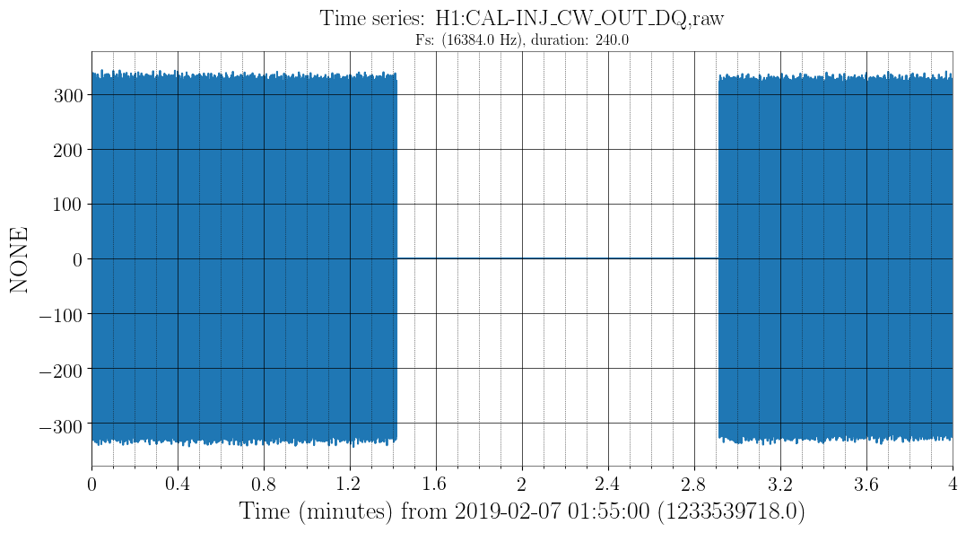
Since some of this work involved redefining the directory structure on h1hwinj1, I have recreated the RELEASE sym link to point to preO3_H1 and have restarted the CW injections to verify things still work, which they seem to do (see attachment).
Sheila, Georgia
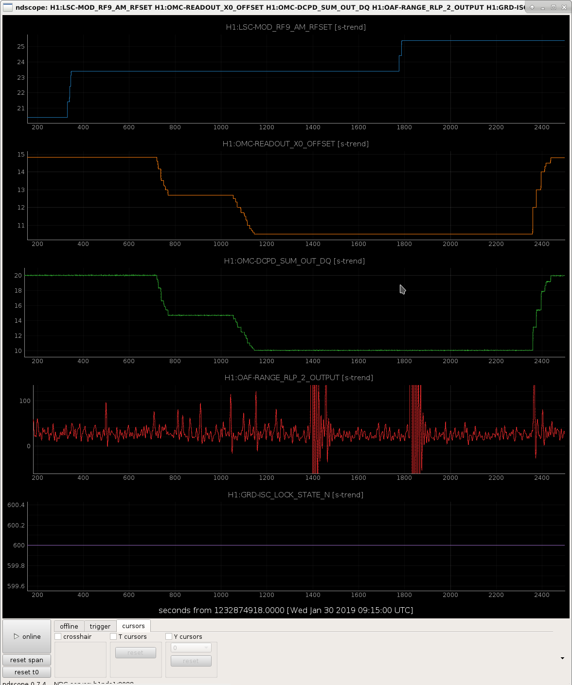
Last week Sheila posted some times where she increased the RF9 modulation depth, and decreased the DARM offset, increasing the coupling of RF9 RIN to DARM.
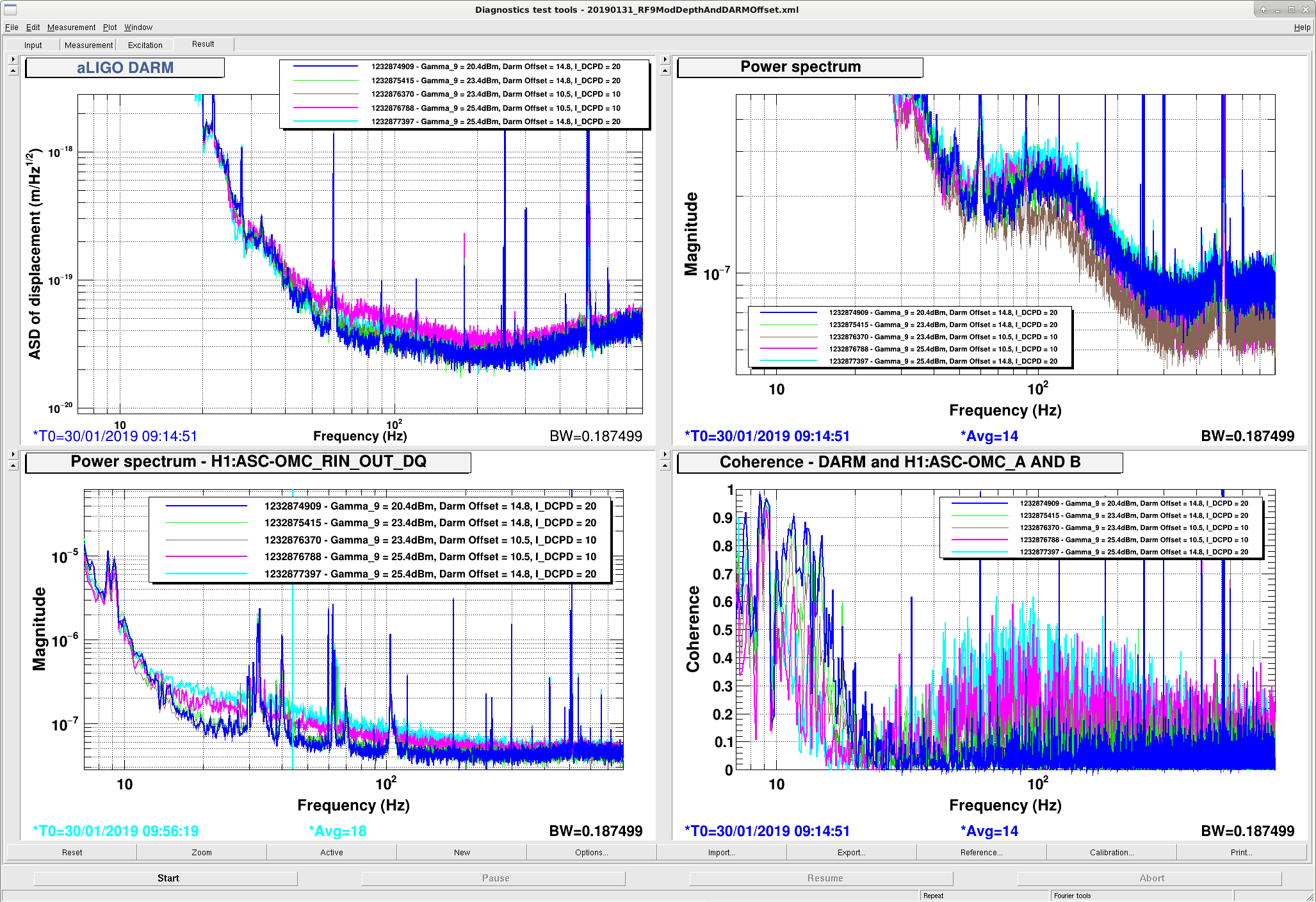
I had a look back at these times, and recorded the DARM spectrum, OMC QPD RIN, and coherence between the QPD RIN and DARM, as well as the DCPD sum channel. First attachment shows these spectra. Note the QPD RIN channel is a new addition which is the sum of the RINs of the two QPDs on the OMC breadboard. The second attachment is just the time series of the modulation depth (dBm), DARM offset, OMC DCPD sum, and the 20-29Hz DARM BLRMS so I can avoid glitchy times.
Things to note from figure 1:
When we first increased the modulation depth from 20 to 23 dBm there is no difference in DARM or the DARM coupling (compare blue and green traces)
When we reduce the DARM offset so that there is 10 mA on the DCPDs (compared to the usual 20 mA), there is still no increased coupling to DARM (brown trace), we see a reduction of noise in the DCPD spectrum which makes sense. There's no change in the QPD RIN. At 20 dBm modulation depth the relative contributions to the RIN are as reported in alog 46490. When we increase the modulation depth, these relative contributions change.
When we further increase the modulation depth to 25.4 dBm (fuchsia trace) we see a broadband increase in the QPD RIN and in DARM (but a decrease in the DCPD spectrum?). Note though that there might be a problem with saturations in the EOM when we increase the modulation depth above 24 dBm.
When we increase the DARM offset back to 20 mA (cyan trace), with this new high modulation depth, the DARM noise decreases (makes sense, less RF9 contribution at higher DARM offset), but the QPD RIN increases, as does the coherence between the QPD RIN and DARM.
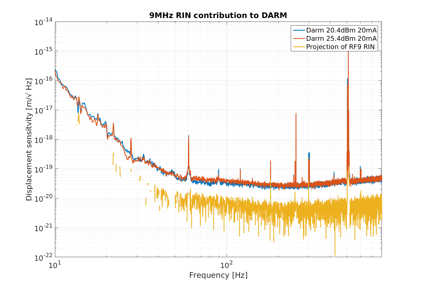
Assuming there's nothing strange going on when we increase the modulation depth by 5dB, we can use this data to make a noise projection. Third attachment shows an attempt at this. We did a quadrature subtraction of the normal (low modulation depth) DARM spectrum from DARM with the increased modulation depth, and then scaled this by the 5dB modulation depth change, which gives the yellow trace.
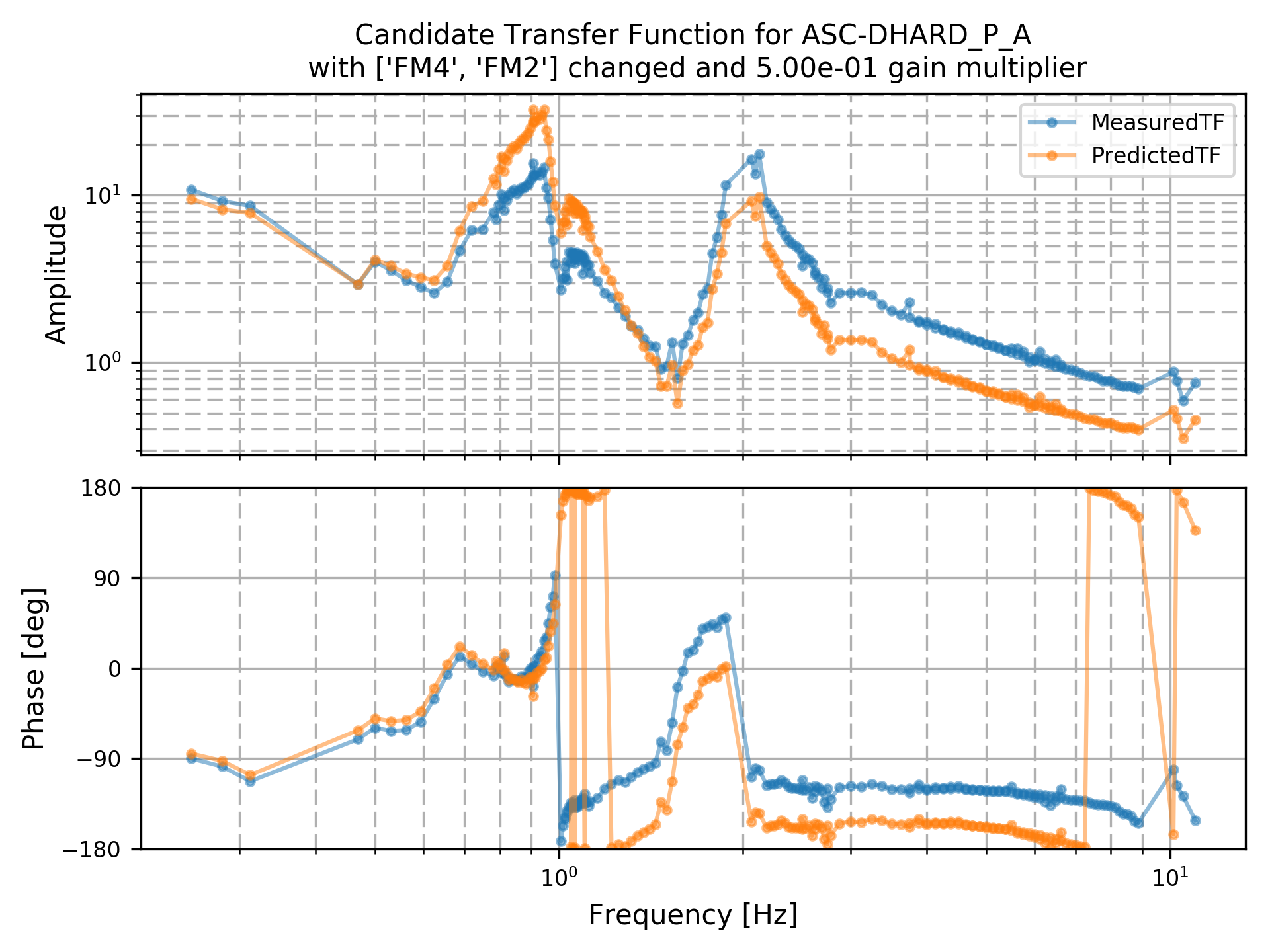
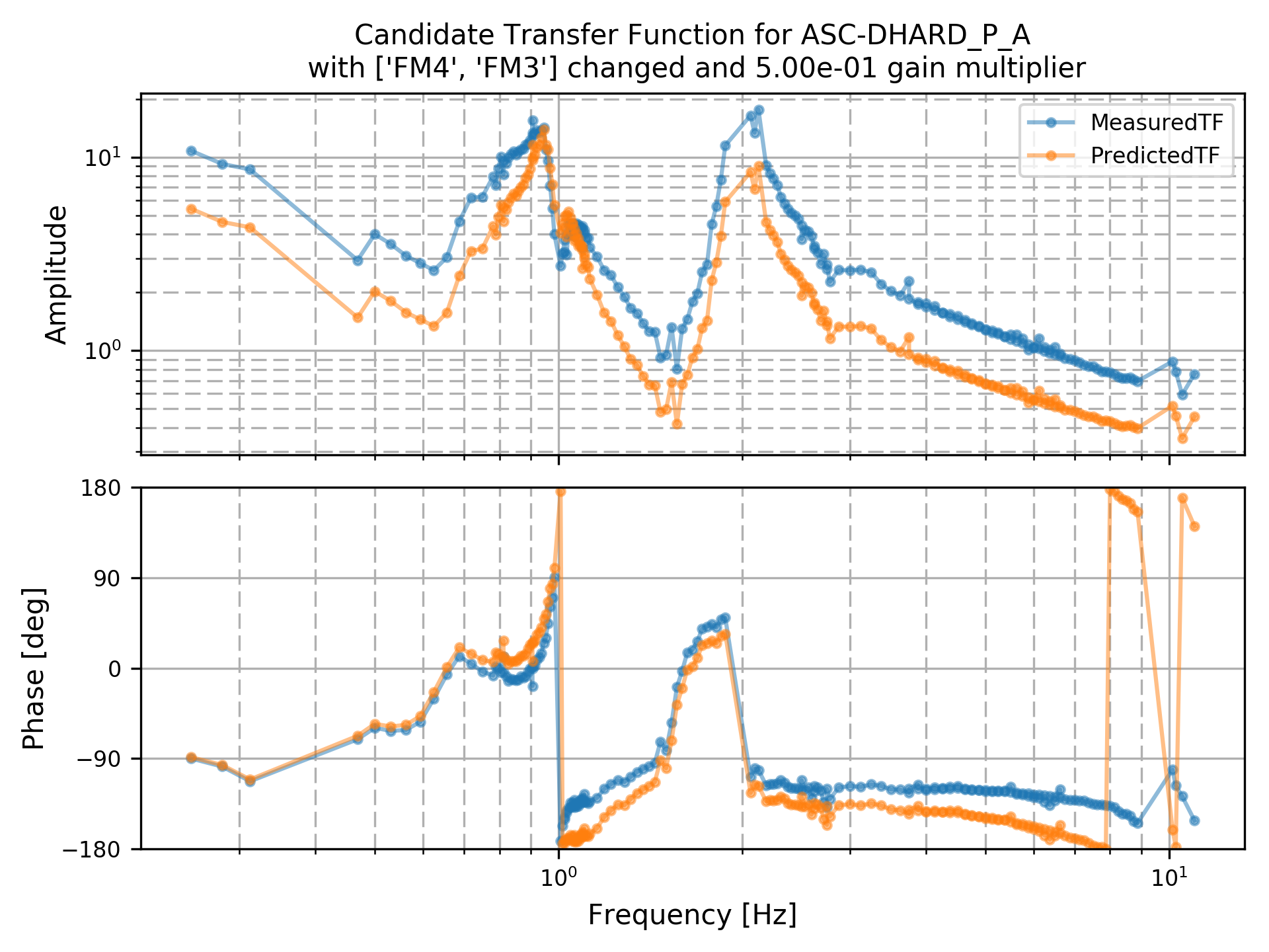
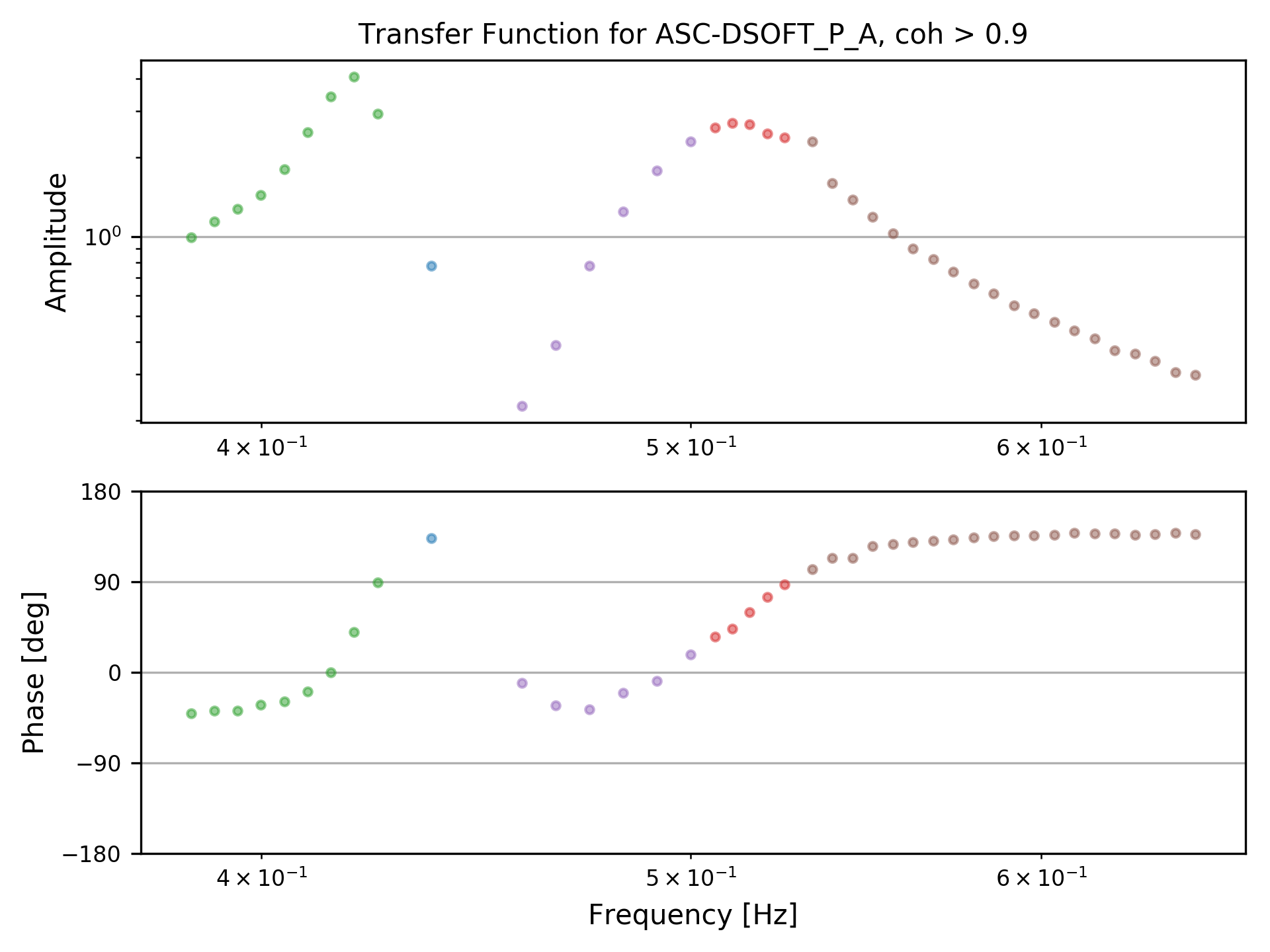
Attached are 2 TFs of DHARD Pit, and one of DSOFT Pit.
In each of the DHARD plots blue is the measured TF (and is the same for both of these 2 plots), and orange is taking that measured TF and applying the gain and filters indicated in the title (during the measurement my DHARD_P gain was -60, rather than the -50 that the guardian would put in, but the orange with the 0.5 gain multiplier puts the gain down to -30, which is where we used to put it at the end of LOWNOISE_ASC). The DHARD plot with boost_cutoff in the name is what our loop would look like with the 1Hz boost filter and the ELP17 lowpass filter, and it's clear that it's very marginal. The DHARD plot with resG_cutoff in the name is what the loop would look like with a resonant gain filter at 1Hz that is narrow enough to not eat very much phase near the 1.5Hz dip. This is the loop that Marie and I put into the guardian this morning, and seems to have worked well for our long lock this morning, except we used a gain of -42 (which, on this plot, would mean a gain multiplier of 0.7 rather than 0.5, so the orange loop should scoot up a little).
The DSOFT plot is just a measurement of the loop that we have, with the DSOFT_P radiation pressure compensation still engaged. We will likely turn off the RPC for the soft loops.
The additional status channels added to guardian in the recent 1.3.1 release have enabled us to now handle all OBSERVATION status logic in the GRD-IFO top node. The following binary channels (0=False, 1=True) indicate the overall OBSERVATION state of the observatory:
The IFO top node is monitoring the status of every other guardian node in the full system. The primary tasks of the top node is to wait until all other nodes are individually reporting OK status. If any node is not reporting OK status, the top node H1:GRD-IFO_READY bit reports False/0(zero). Once all nodes are reporting OK, the READY bit flips to True/1.
The top node has two requestable states: "OBSERVE" and "COMMISSION". These states represent the intent of the human observatory staff. When the "OBSERVE" is requested (and the top node is not "stalled") the H1:GRD-IFO_INTENT bit will be True/1. Otherwise it will be False/0.
Once both the READY and INTENT bits are both True, the system will proceed to the OBSERVE state, and the H1:GRD-IFO_OK bit will flip to True/1. This will indicate that the observatory is in OBSERVATION/SCIENCE mode.
The top node can also be in one of two operational modes: MANAGED or AUTO.
In MANAGED mode, the on-shift operator is expected to re-confirm intent *after* the system has transitioned to READY and before the system will flip the OK bit. Observation intent is expressed by re-requesting the "OBSERVE" state.
In AUTOMATIC mode, which is intended for unattended operation of the facility, no reconfirmation of intent will be required after transitioning to READY. Once the "OBSERVE" state has been requested, the OK bit will flip as soon as the READY bit flips. In other words, in AUTO mode, if the OBSERVE state is requested, we will go straight to observation mode as soon as the IFO locks and all guardian nodes report OK status.
The OBSERVATION_OVERVIEW MEDM screen has been updated to expose all of the above behavior in an intuitive way (very similar to how it was in O1 and O2). This screen can be viewed independently, but it is also primarily embedded into the top of the GUARD_OVERVIEW screen.
To illustrate the above behavior, we examine the OBSERVATION_OVERVIEW screen using an "IFO2" node acting as a stand-in for the IFO top node, monitoring a single "TEST" node acting as a stand-in for the full guardian hierarchy.
When the interferometer is not in it's final configuration (e.g. TEST node not OK), the screen looks like this:

The READY, INTENT, and OBSERVE boxes are all orange, indicating that their values are False.
Note that we are in "MANAGED" mode: the box on the left is purple and the "MANAGED OPERATION" button is highlighted. This means that the operator will always need to confirm OBSERVE before final observation.
Once the instrument reaches the nominal low noise state (e.g. TEST_OK = True), the READY bit will flip to True, and the READY box will turn green:

Note that the INTENT box is now yellow, indicating that the operator must re-confirm the intent to go to OBSERVE. Once the operator confirms intent by clicking the "OBSERVE" button, the OK bit flips and we are in the full OBSERVE state:

If we lose lock, all status bits are reset to False (the INTENT box is yellow to indicate that the INTENT bit was forcibly unset by lock loss because of being in MANAGED mode):

In AUTO mode (left box blue and "AUTOMATIC OPERATION" button highlighted), if we lose lock, the READY bit flips but the INTENT bit remains set:

Once nominal low noise is regained and the READY bit flips, the OK bit also flips immediately and the system goes straight back into OBSERVE:

The following channels have been added to the GDS broadcaster frames:
The following channels were already frames:
The ISC_LOCK OP/MODE/ERROR channels are not really required anymore, since all that information is now better encapsulated in the ISC_LOCK_ACTIVE channel. If you want to know the state of the ISC_LOCK guardian node look at ISC_LOCK_STATE_N with ISC_LOCK_ACTIVE==1. Once downstream consumers move to using the ACTIVE channel we should be good to remove the OP/MODE/ERROR channels.
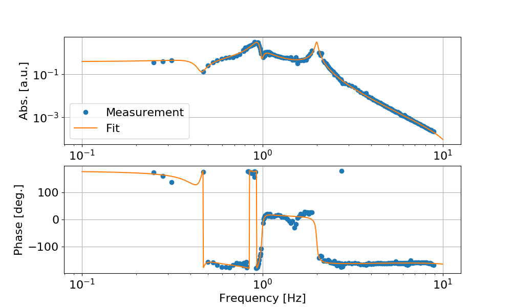
I used a recent measurement of the DHARD pitch transfer function done by Jenne, to extract the plant transfer function and fit it. The idea was to identify why there is that spurious phase rotation around 1 Hz.
It turns out that the phase rotation is not due to a right-half-plane zero (that would have resulted in a phase rotation in the other direction) but it is due to a right-half-plane pole at 0.96 Hz.
In a ideal case, the plant should have two stable (left-half-plane) double poles corresponding to the two mechanical resonances (we are actuating from L2). Those two double poles are indeed there at 0.95 Hz and 2.0 Hz. But there is also a close double-pole / double-zero pair at about 1 Hz. This can be due to cross-couplings from other loops. In normal, stable conditions, this pair would produce a small wiggle in the phase, since a stable double pole would induce a phase rotation of -180 degrees and a double zero a phase rotation of +180 degrees. But the double pole in this case is unstable, so its phase rotation is +180 degrees, and this cancels out the -180 from the 0.95 Hz stable double pole.
Interestingly, if I use the plant fit and the control filter, and simulate the system stability with MATLAB's sisotool, I find out that the loop is indeed stable. So the situation seems to be that cross-coupling of DHARD with another loop creates a unstable pole/zero pair at about 1 Hz. And the current DHARD design is good enough to stabilize it. This is not that surprising, since the unstable pole has reasonably large Q, so it's not that hard to stabilize. Also I think that once the cross-coupling is fixed, the current loop shape should still give a stable feed-back (assuming we just remove the pole/zero pair).
For reference, see below the fit parameters
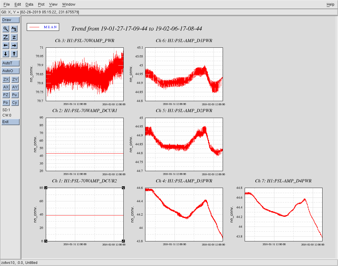
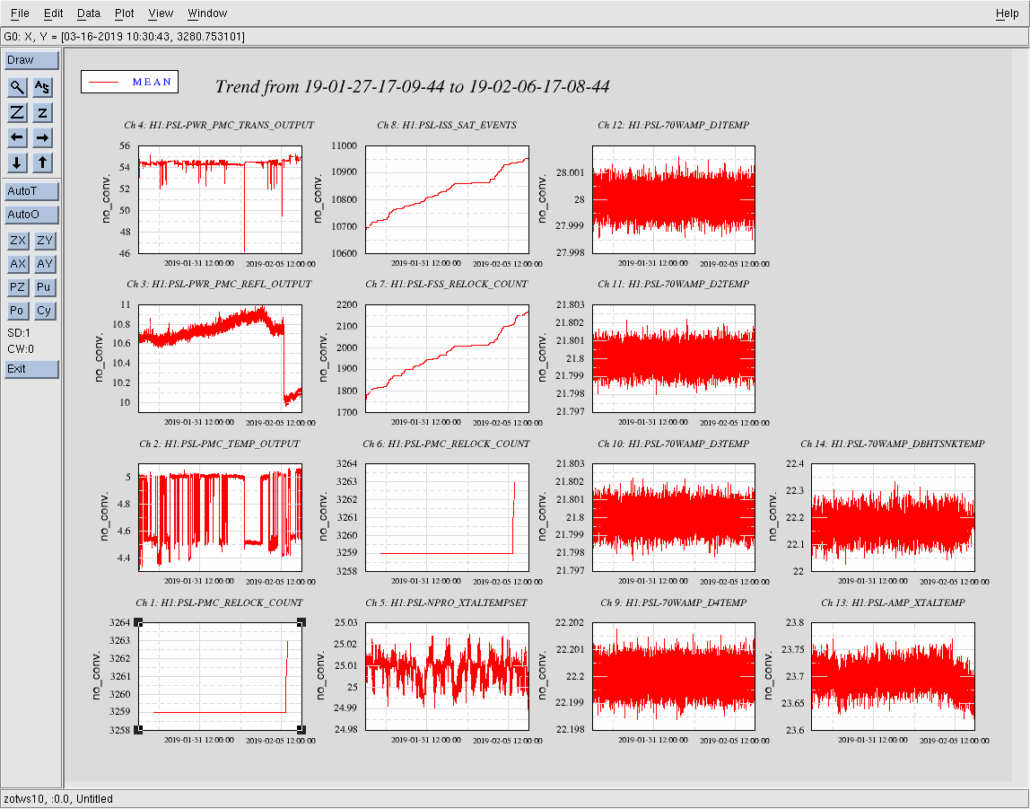
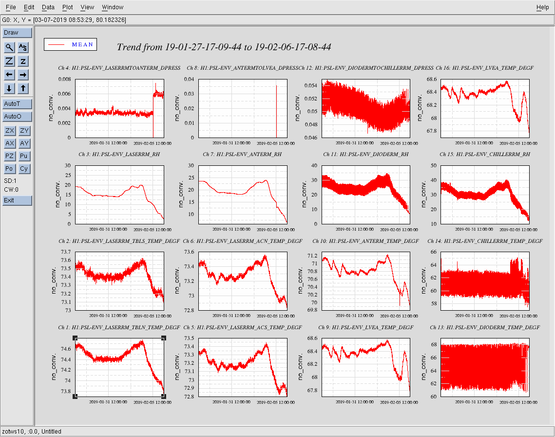
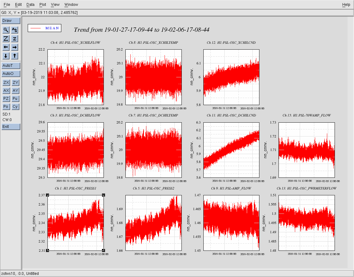
All trends look nominally ok. There seems to have been a decrease in temps in the laser room by a degree, or so.
Sheila, Daniel, Terry, Nutsinee, Craig, Jenne, and others who were cheering in the control room
We used the lowest amount of CLF we could reasonably operate at, 0.05mW into the coupler. 20.5 mW of pump was sent into the coupler on the ISCT6 (this corresponds to ~2.6-2.7 mW hitting the OPO, the nlg wasn't optimized before we injected the squeezing but that's about the best we've seen). We read -15dB of 3MHz demod signal from the Homodyne. The common gain at the LO common mode board was 7dB which gave us a UGF of 10kHz with plenty of gain margin. Boost 1 and 2 on the common path was turned on.
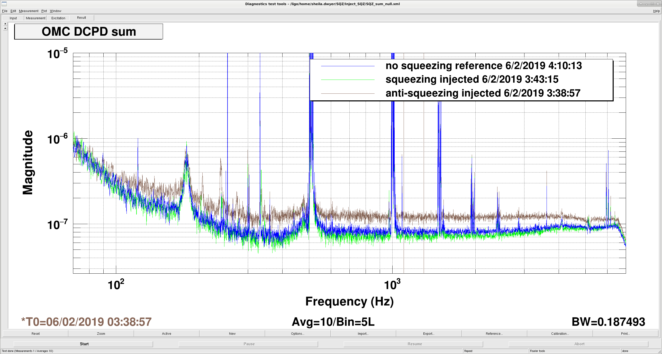
Sheila has the sqz/asqz plot and the OMC DCPC traces. I have LO phase noise measurement. We will be posting these plot later.
Things we could optimize still is the alignment (which wasn't done at the beginning of the lock acquisition, we did try our best to optimize it while the LO was locked). A single bounce measurement with tonight's alignment should give us a loss estimate.
We locked the interferometer in a state that had a lot of DHARD noise, so that we would have a chance to make some measurements with the squeezer. The DHARD noise is dominating the spectrum below about 300 Hz.
Some times:
First set of measurements, before Nutsinee pushed the LO loop ugf to about 10 kHz and added the boosts:
After the LO loop was set and we made some small alignment tweaks:
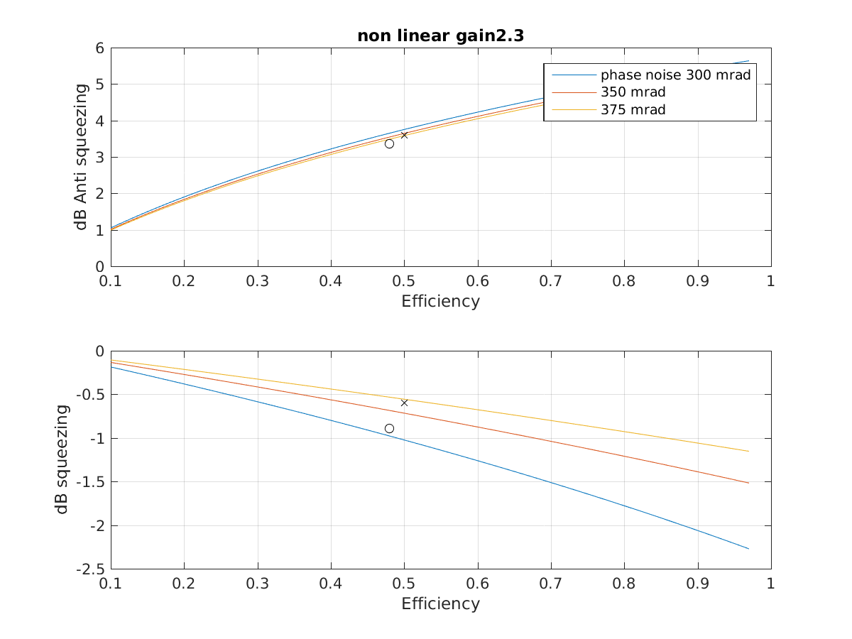
The second attachment shows what these squeezing and anti-squeezing levels roughly mean for a nonlinear gain of 2.3 which is what Nutsinee measured. This indicates that our total efficency is something around 50%, since we have 19.5% known losses this means that we have almost an additional 40% losses somewhere. We tried to walk the beam a littel using ZM1+2, but we would like to take some time with the squeezer beam reflected off the SRM and the interferometer unlocked to make sure that we are not close to clipping on anything. The first measurement taken before Nutsinee adjusted the LO loop implies something between 350-375 mrad of phase noise, after tuning the loop we saw a bit more squeezing but this still implies a large phase noise, something between 300 and 350 mrad.
Fantastic!
Nicely done LHO Team!
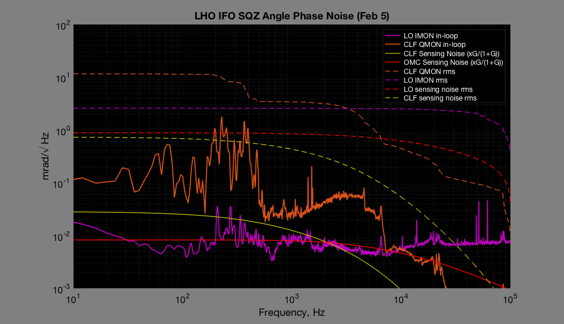
Here's a quick look at the sqz angle phase noise from that night. I haven't had time to add them all up but this plot should give you all the information you need. Right now we believe that LO is mostly seeing CLF noise and its own sensing noise. So the low limit sqz angle phase noise is sqrt(CLF rms^2 + CLF sensing rms^2 + LO sensing rms^2). Look at ~100Hz for example, the low limit of sqz angle phase noise would be sqrt(11.4^2+0.69^2+0.88^2) = 11.5 mrad.

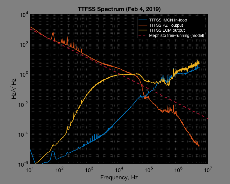
Also attached a very crude plot of an in-loop TTFSS spectrum up to 5 MHz for those who might be interested. Overall noise projection is coming.
*update* The previous TTFSS plot wasn't calibrated properly. I've replaced the plot with a new one that's actually in Hz/sqrt(Hz).
Awesome!
Dean, Filiberto, Daniel, Jenne, Rich Following up on work done by Koji wherein he discovered that multiples of the IFO sidebands can resonate in the OMC cavity, a revision has been made to the OMC High Voltage Driver Chassis (D1300485). The OMC higher order mode (HOM) content changes due to deformation of the OMC cavity mirrors as voltage is applied to the OMC piezos. The OMC piezos are donut shaped and do not simply move a mirror in piston motion. The mirror, which is glued rigidly to the piezo, is stressed as well as translated in piston motion by the piezo, which changes the radius of curvature of the OMC cavity mirrors. It is this effect that changes the HOM content of the OMC cavity. Attached are some diagrams that will simplify the explanation of the changes made to the OMC High Voltage Driver Chassis. In a nutshell, an additional high voltage driver was added to drive one side of the piezo used to perform the shutter function and inject a dither. The other side of this same piezo is still attached to the Low Voltage Driver board within the OMC High Voltage Driver Chassis. A result of this topology change is that the sign of the dither flips, and the amplitdue of the dither is reduced by a factor of 1.5. This reduction in amplitude may be due to the source impedance of the high voltage driver circuit now terminating the other side of the piezo used to inject the 4.2kHz dither signal. This source impedance looks like 50kohms in parallel with 0.47uF. Effectively the piezo and the terminating capacitor form a capacitive voltage divider. The factor of 1.5 was derived by Jenne looking at the change in the OMC length locking loop gain before (by archived transfer function thanks to Shiela) and after the modification. This is a bit odd though as it would imply that the piezo capacitance is of order 1uF, which seems high. Another possibility is that the archived transfer function differs from the transfer function taken today due to some other factor unrelated to dither amplitude. We don't know yet, but once the value of the OMC piezo capacitance is known, the calculation can be made. 1. The serial number of the chassis removed from ISC-R5, slot 13 is S1301298 2. The serial number of the modified chassis returned to ISC-R5, slot 13 is S1301297 3. The serial number of the chassis taken from 3rd IFO to donate the new HV driver board is S1301299. D060283 circuit board S1301295 was removed from this chassis and is now installed in the modified chassis as the OMC length loop HV driver as shown in the attached PDF containing a high resolution photo of the modified chassis. 4. A Y-cable was added to use two unused ADC channels previously associated with the HAM6 RFPD Interface chassis channels 3 and 4. These channels are now used to read the DC (channel 3) and AC (channel 4) of the newly installed additional HV driver board within the modified chassis. Details of this cable are shown in the attached PDF.
Koji informs me that the manufacturer's nominal OMC piezo capacitance is 510nF. This is similar to the terminating capacitance, so the dither reduction factor of 1.5 that Jenne derived by before and after comparison of the OMC OLTF gains is likely to be real, and should be compensated by an increase in the dither amplitude as she thought.
Verified that the two HV drives to the PZTs have the same polarity. Adding a slow ramp to the bias of the new PZT, when the OMC is locked, shows the servo PZT reacts in the opposite direction to compensate.