Displaying reports 43221-43240 of 88625.Go to page Start 2158 2159 2160 2161 2162 2163 2164 2165 2166 End
Reports until 14:22, Tuesday 05 February 2019
H1 SEI (CDS, OpsInfo)
jim.warner@LIGO.ORG - posted 14:22, Tuesday 05 February 2019 - last comment - 09:17, Wednesday 06 February 2019(46795)
SEISMON got broken by the FS issues yesterday, running again

I noticed yesterday that Seismon was not recovered after the file system issues yesterday, but I caught it after Carlos had left for the day, so I didn't get to ask if they were still recovering. Working with Carlos this morning I was able to get it back up and running, but I wanted to capture the process here.

1. ssh onto the seismon vm as controls:

    ssh controls@seismon

2. Launch 2 screen sessions for the seismon scripts, this is not completely straight forward. The scripts live in /usr/local/seismon/seismon/bin, but 2 of them need a virtual environment, which I launched using an alias:

controls@seismon:~ 0$ cd /usr/local/seismon/seismon/bin
controls@seismon:bin 0$ screen

Activate the virtual environment for seismon:

controls@seismon:bin 0$ seismon_ve 

Then run the traveltimes script:
 (ve) controls@seismon:bin 0$ ./seismon_run_traveltimes.py

This will start outputting stuff to the terminal, so leave it running and CTRL+A+D to disconnect from the screen session, launch a new screen session and repeat for seismon_run_info, including the seismon virtualenv (seismon_ve alias).

3. The run a third screen session for the epics client seismon_epics_client_v5.py. this does NOT use the seismon virtualenv, and won't run with it set. When done there should be 3 screen sessions running.

controls@seismon:bin 0$ screen

controls@seismon:bin 0$ ./seismon_epics_client_v5.py

4. There is also an epics IOC on h1fescript0, ssh to that machine as controls and ps -elf | grep seis to see there is only one copy of seismon_epics_ioc_v3.py running.

controls@h1fescript0:~ 0$ ps -elf |grep seis
0 S controls  2952  2590  1  80   0 - 32756 poll_s  2018 pts/2    18:20:36 python ./seismon_epics_ioc_v3.py
0 S controls  4532  4301  0  80   0 -  2350 pipe_w 14:21 pts/0    00:00:00 grep --color=auto seis

That should be it.


Comments related to this report
jeffrey.kissel@LIGO.ORG - 14:34, Tuesday 05 February 2019 (46796)
FS = "file system"

These recovery instructions are for issues with Seismon are related to cdsfs0 going down on Monday afternoon. See some details from Carlos / Jonathan in 46767.
jim.warner@LIGO.ORG - 09:17, Wednesday 06 February 2019 (46823)CDS

I forgot to add that the USGS java client needs to be running on the seismon machine as well. This lives in /usr/local/seismon/ProductClient, there is a script called init.sh. This is launched with the command:

controls@seismon:ProductClient 0$ ./init.sh start

However, the client often gets confused or something by old data in the /usr/local/seismon/ProductClient/data folder, it's probably best to remove this folder:

controls@seismon:ProductClient 0$ rm -rf data/

When the client starts, it will populate this folder and subfolders. I think it works okay to remove this folder while the client is running, but if that doesn't work the USGS client can be stopped with:

controls@seismon:ProductClient 0$ ./init.sh stop


H1 TCS (AWC, TCS)
daniel.vander-hyde@LIGO.ORG - posted 13:48, Tuesday 05 February 2019 (46787)
SRM heater alignment update (Now aligned in yaw. Clipping is no longer an issue)

TJ, Marie, TVo, Danny

TJ set up a temporary rail for the table to slide along to avoid the table from changing angle of incidence on the first in-vaccum mirror when shifting the table position.

After shifting the table a bit more to the left of where we nominally were trying, we were able to pass the CO2 beam through the ifo beam position in yaw (using the procedure detailed in alog 46766). I forgot to take photos of the red alignment laser position on the Zn-Se viewport and SRM-HR baffle but I'll supplement this post with those photos as a comment next Tuesday.

There was quite a bit of pitch motion/drift on the AS_A_DC and AS_B_DC pds. Not very clear why this was, but the motion made it difficult to verify the pitch alignment was still good. We might have to double check next Tuesday (or sooner if there is a need to test) but I suspect that we are nominally in a good position in pitch since we made very little changes. 


H1 CDS (DAQ)
david.barker@LIGO.ORG - posted 13:03, Tuesday 05 February 2019 (46789)
CDS Maintenance Summary: Tuesday 5th February 2019

ODC removal

Keita, Jeff, Jamie, Dave:

The following models were restarted after ODC removal: h1sus{etm[x,y], tms[x,y], itm[x,y], bs, pr[m,2,3], sr[m,2,3], mc[1,2,3], omc, opo, im, htts} h1isietm[x,y], h1isce[x,y].

ISC model changes:

Jenne, Daniel, Dave:

The following models were restarted: h1ascimc, h1omc

Guardian new base code:

Jamie:

h1guardian1's guardian base was updated. Its OS was upgraded and the machine was rebooted. The EDCU to connect to the new channels.

h1odcmaster removal

Dave:

I completed the h1odcmaster model removal from the DAQ with a new H1EDCU_DAQ.ini.

DAQ Restart

Dave:

The DAQ was restarted at 11:44PST for the above changes.

H1 CAL
evan.goetz@LIGO.ORG - posted 12:41, Tuesday 05 February 2019 (46788)
Installed whitening filters in CFTD paths
After the CAL-CS model upgrade to have highpass/whitening filters on the CFTD CTRL paths, I've installed whitening filters on the CFTD paths. This is the same as we did at LLO (see LLO aLOG 42961). This has to be installed on both inverse sensing and actuation paths, but does not need to be in the CFTD_DELTAL_EXTERNAL whitening bank. We will dewhiten in DTT.

These are installed in FM1 of the CFTD_DARM_ERR bank and FM1 for each of the CFTD_DELTAL_CTRL*_HP banks.

The design string is: zpk([0.3;0.3;0.3;0.3;0.3;0.3],[30;30;30;30;30;30],1,"n")
H1 SEI (FMP)
jim.warner@LIGO.ORG - posted 11:52, Tuesday 05 February 2019 - last comment - 13:56, Tuesday 05 February 2019(46785)
Temperature changes at endstation almost drove BRSX out of ranger overnight

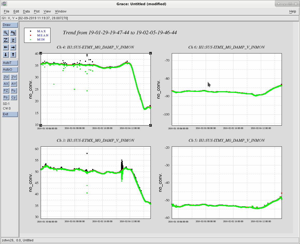
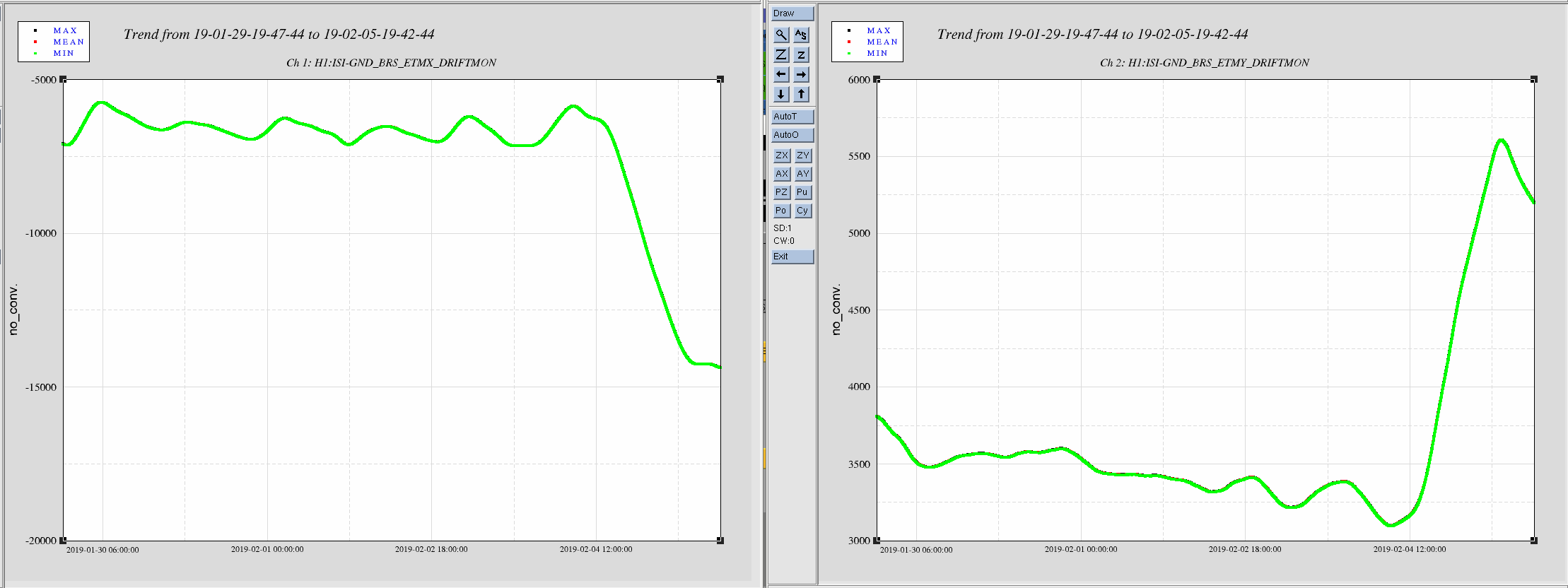
Overnight the end station BRS enclosures at both endstations heated up about .5 degrees C. This very nearly drove BRSX out of range, which would have probably tripped the ISI. This wasn't a big issue for BRSY, but BRSX went through 8k counts of the ~28k usable range, it probably also has an effect on the noise of the BRS. The damping for the BRS also goes unstable when the ccd image goes out of range.

Attached plot shows trends for the last week of each BRS driftmon, X is the left image, Y is the right. The BRS go out of range at about +/- 15000 counts, BRSX will need adjusted immediately, unless temperatures are changing back.
Was there some change to building heating or something? Nothing was changed on either BRS enclosure.

Images attached to this report
Comments related to this report
jim.warner@LIGO.ORG - 12:05, Tuesday 05 February 2019 (46786)FMP

All 4 quads also see movement over the same time period. Attached trends are the last week of the quad topstage osems.

Images attached to this comment
bubba.gateley@LIGO.ORG - 13:20, Tuesday 05 February 2019 (46790)
The FMCS controlled set point was not changed at either end station.  
aidan.brooks@LIGO.ORG - 13:31, Tuesday 05 February 2019 (46791)

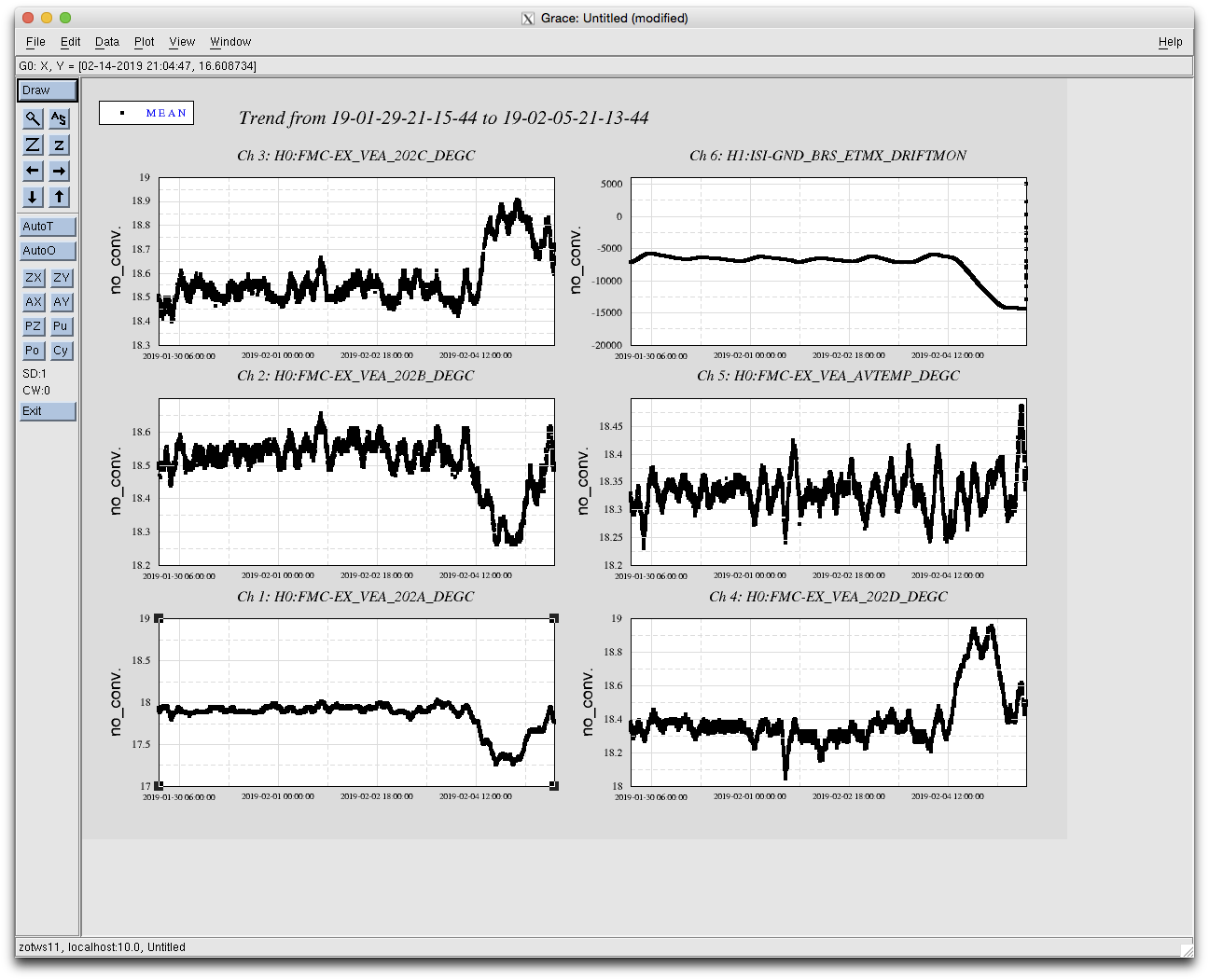
We've seen a similar issue before with the ETM temperature. It stems from the fact that the HVAC is stabilizing the average temperature of 4 temperature sensors: (A+B+C+D)/4.

The ETM chamber is down at one end of the building (near A & B). If, for example, the local temperature rises at the other end of the building (near temperature sensors C&D) then the HVAC reacts to keep the average temperature constant. A little bit of math shows that if C+D becomes hotter than A+B must become cooler. (Or it could be that the region near A is getting cooler and forcing C+D to get hotter - which is probably more likely given the current weather).

You can see that the ETM BRS DRIFTMON is much more strongly correlated with individual temperature sensors than with the average temperature. Stabilizing the VEA temperature to (A+B)/2 should minimize this issue.


Here's similar data from the LLO ETM - the RH RTD is much more strongly correlated with the 202B temperature sensor than it is with the average temperature.


Images attached to this comment
jim.warner@LIGO.ORG - 13:56, Tuesday 05 February 2019 (46794)FMP

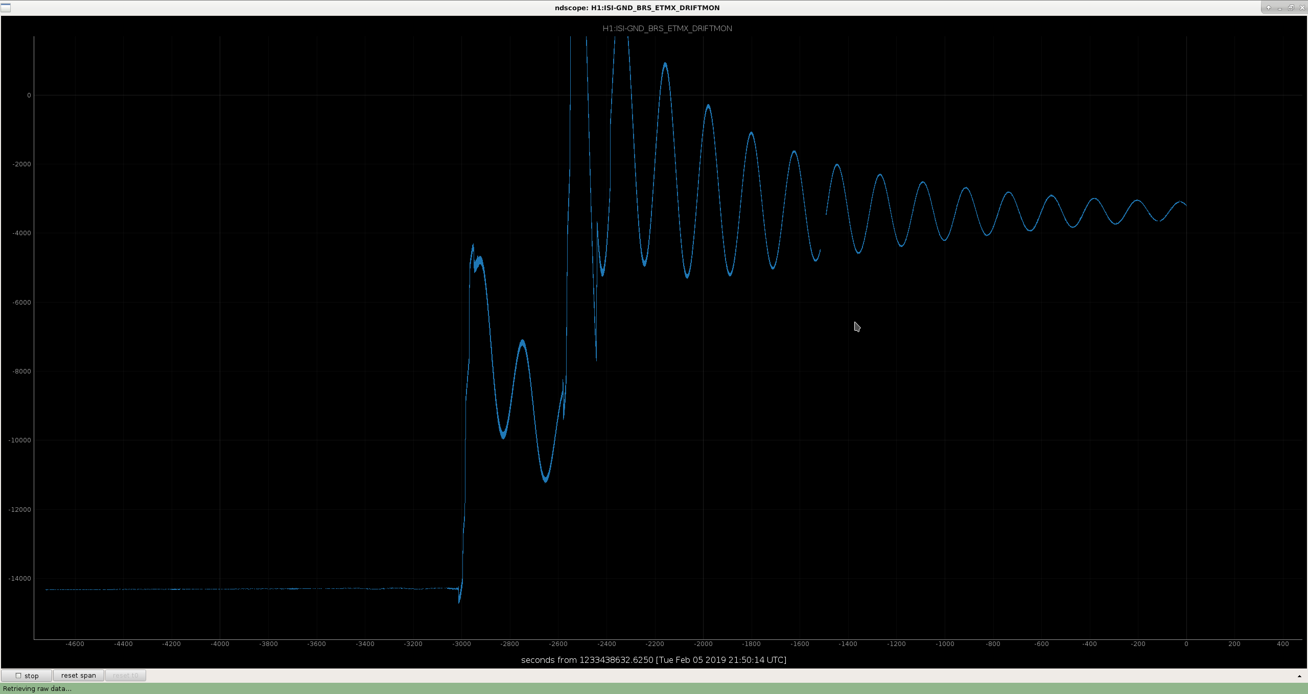
I've done a quick rebalance of BRSX to get it closer to the middle of it's range, it's still damping down and temperatures will take a little while to stabilize. We may want to think about some weekly-ish checks of things that can get driven by temperature swings? I don't know what that would look like.

Images attached to this comment
H1 AOS
jeffrey.kissel@LIGO.ORG - posted 10:45, Tuesday 05 February 2019 - last comment - 16:34, Tuesday 05 February 2019(46784)
Accepting QPD Offsets in ISCEX/EY Models Before Restarts to Remove ODC
J. Kissel
8077

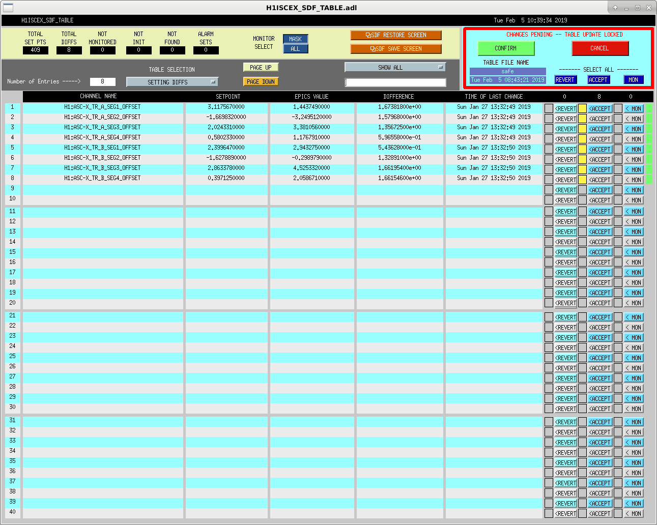
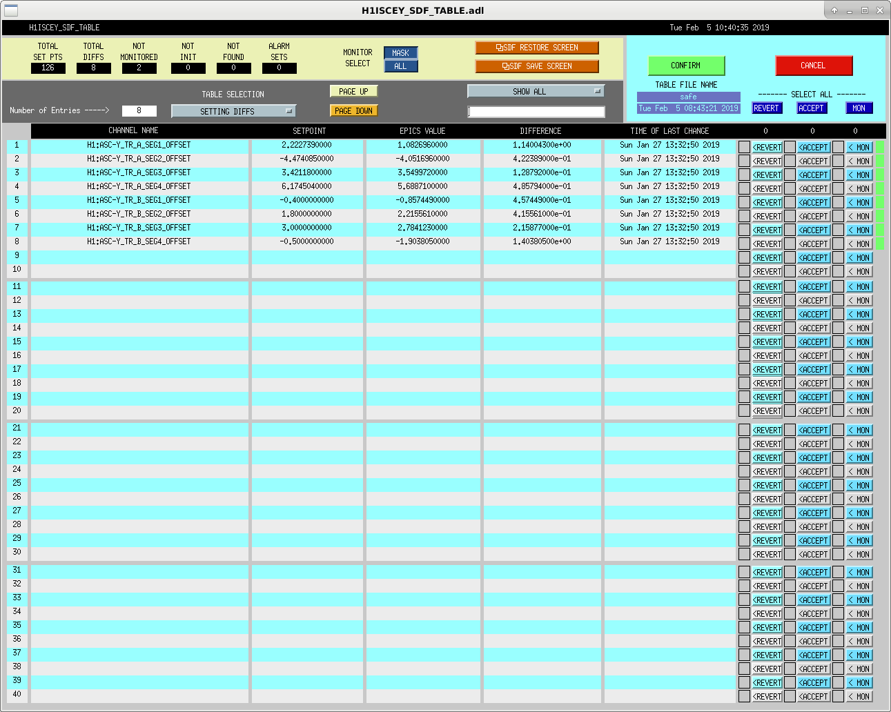
Reconciling SDFs prior to the h1iscex/h1iscey model restarts, I've accepted QPD offsets that were last changed on Jan 27th 2019. see attached screenshots.
Images attached to this report
Comments related to this report
keita.kawabe@LIGO.ORG - 16:34, Tuesday 05 February 2019 (46802)

Some of h1susetmx and h1susetmy L2 GAINs and associated TRAMPs were accepted.

Channel new (old)

H1:SUS-ETMX_L2_DRIVEALIGN_P2L_GAIN 2.647711781 (2.655)

H1:SUS-ETMX_L2_DRIVEALIGN_Y2L_GAIN 3.2292331724 (2.7)

H1:SUS-ETMX_L2_LOCK_P_GAIN 1.05 (1.04)

H1:SUS-ETMX_L2_LOCK_Y_GAIN 1.0 (0.99)

H1:SUS-ETMY_L2_DRIVEALIGN_P2L_GAIN 3.5500448048 (3.4)

H1:SUS-ETMY_L2_DRIVEALIGN_Y2L_GAIN 0.8850832254 (1.95)

H1:SUS-ETMY_L2_LOCK_P_GAIN 0.94 (0.96)

H1:SUS-ETMY_L2_LOCK_Y_GAIN 1.0 (1.01)


ETMX sus callines were disabled (because we haven't successfully get back to EX-only), and ETMY sus callines were enabled instead, and were accepted.

H1:SUS-ETMX_L1_CAL_LINE_CLKGAIN 0

H1:SUS-ETMX_L2_CAL_LINE_CLKGAIN 0

H1:SUS-ETMY_L1_CAL_LINE_CLKGAIN 150

H1:SUS-ETMY_L2_CAL_LINE_CLKGAIN 400

H1 PSL (PSL)
peter.king@LIGO.ORG - posted 09:19, Tuesday 05 February 2019 (46782)
Attempted TTFSS transfer function measurements
This morning I attempted to measure some transfer functions of the TTFSS out by the PSL rack.  In short, it
didn't work.  Enabling the TEST2 input did not do anything.  The switch can be enabled inside the enclosure
however.  I also took some noise measurements of the fast and EOM when the fast gain was varied between
9 dB and 19 dB.

    Unfortunately I cannot retrieve the data from the floppy disc because either my floppy drive does not
work (unlikely) or I did not pay attention as to what format the HP4395A formatted the disc to (LIF as
opposed to DOS).

    Fixing the TTFSS field box will require some laser down time, or more correctly, some FSS down time.
H1 AOS
craig.cahillane@LIGO.ORG - posted 04:49, Tuesday 05 February 2019 - last comment - 03:50, Wednesday 06 February 2019(46781)
Nominal Low Noise tonight
- There is an unsolved problem somewhere around DARM_TO_RF.  I believe it has to do with the DIFF PLL OFFSET stepper servo not quite working fast enough to keep H1:ASC-AS_A_RF45_Q_SUM_NORM near enough to 0 before the switch happens.  I am able to slowly step through the state successfully, but not request beyond it with the guardian without losing lock.

- I removed REDUCE_RF9_MODULATION_DEPTH from the guardian path because this seemed to trigger the 1.4 Hz DHARD instability.  I have been able to sit at NLN for 6 hours without problems.

- We are still controlling DARM with L1 and L2 on ETMY and L3 on ETMX.  Because of this the calibration is a complete mess at low frequency.  At high frequency it is good to one percent (assuming we trust the PCAL at this point, unclear if we do because the force coefficients are changing.)
I fiddled with the DARM calibration screens and switched the calibration back to ETMY L1 L2 such that the DARM calibration should be good to 15% according to PCAL.

Some notes about the noise with the actuator switch:

- MICH FF would need retuning, since MICH is coherent with DARM.  
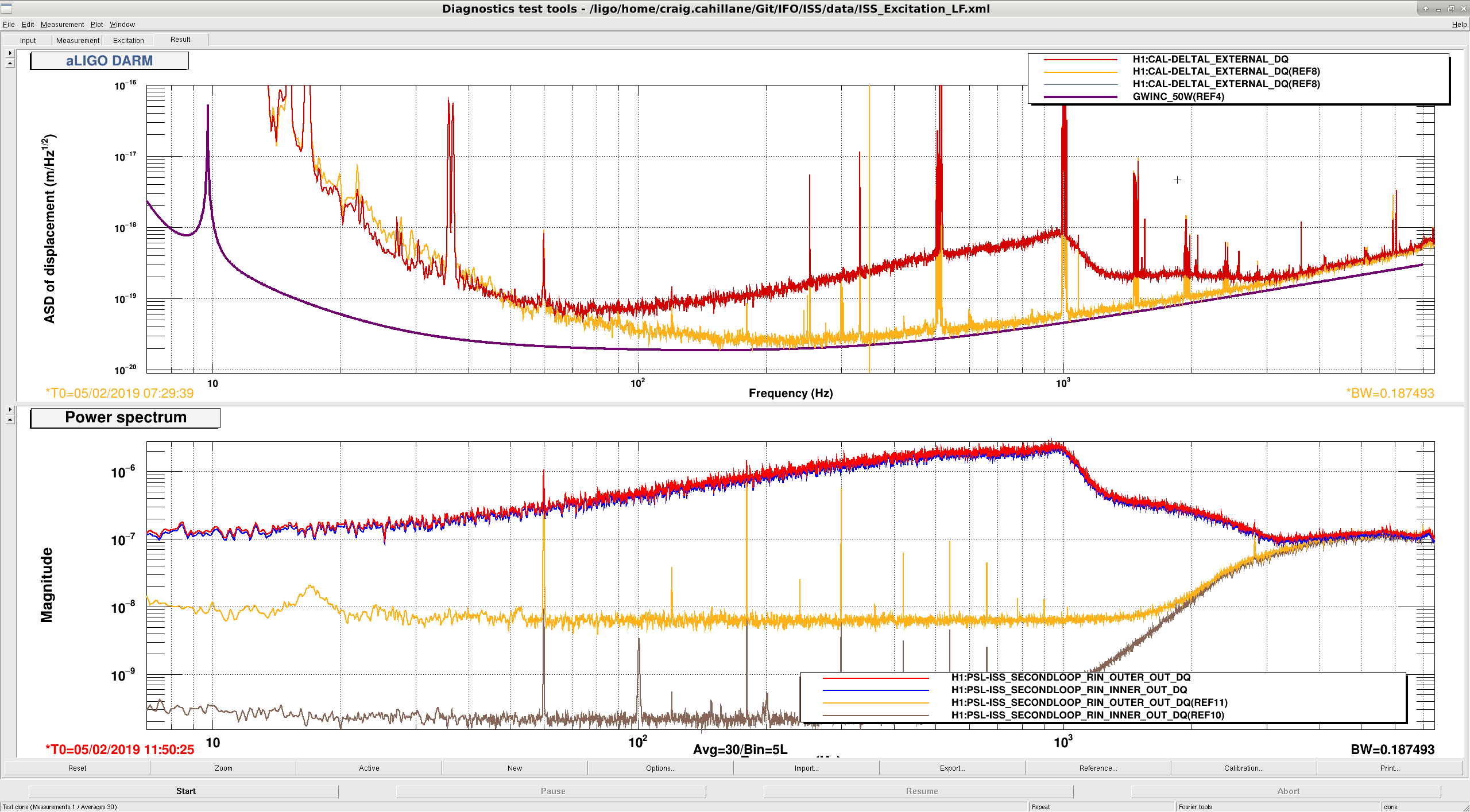
- The ISS coupling to DARM was reduced at high frequencies.  However, after two hours of sitting locked at NLN, the ISS is back to limiting high frequency DARM.
- The scatter shelf is back and happens pretty consistently every two minutes.

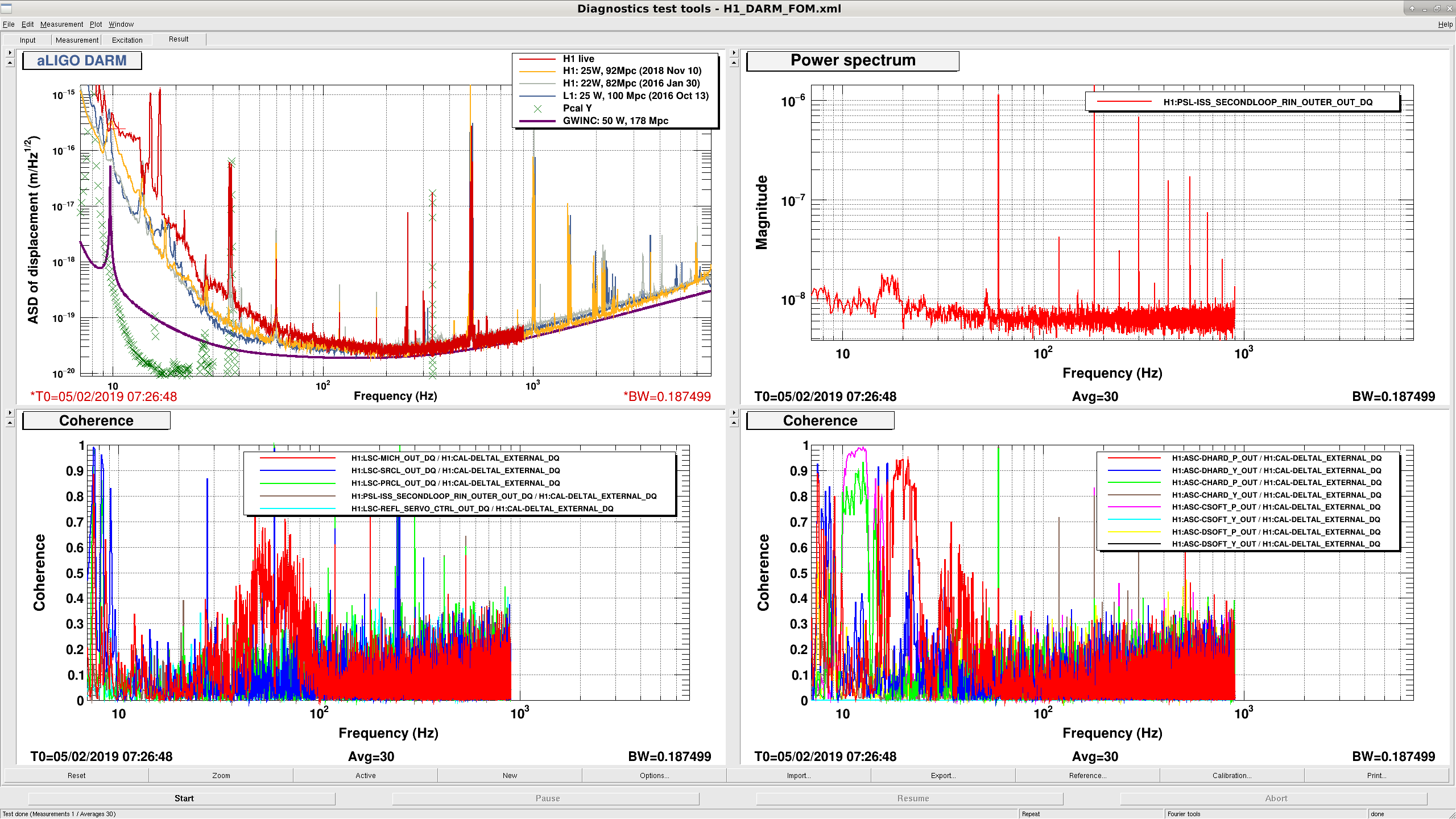
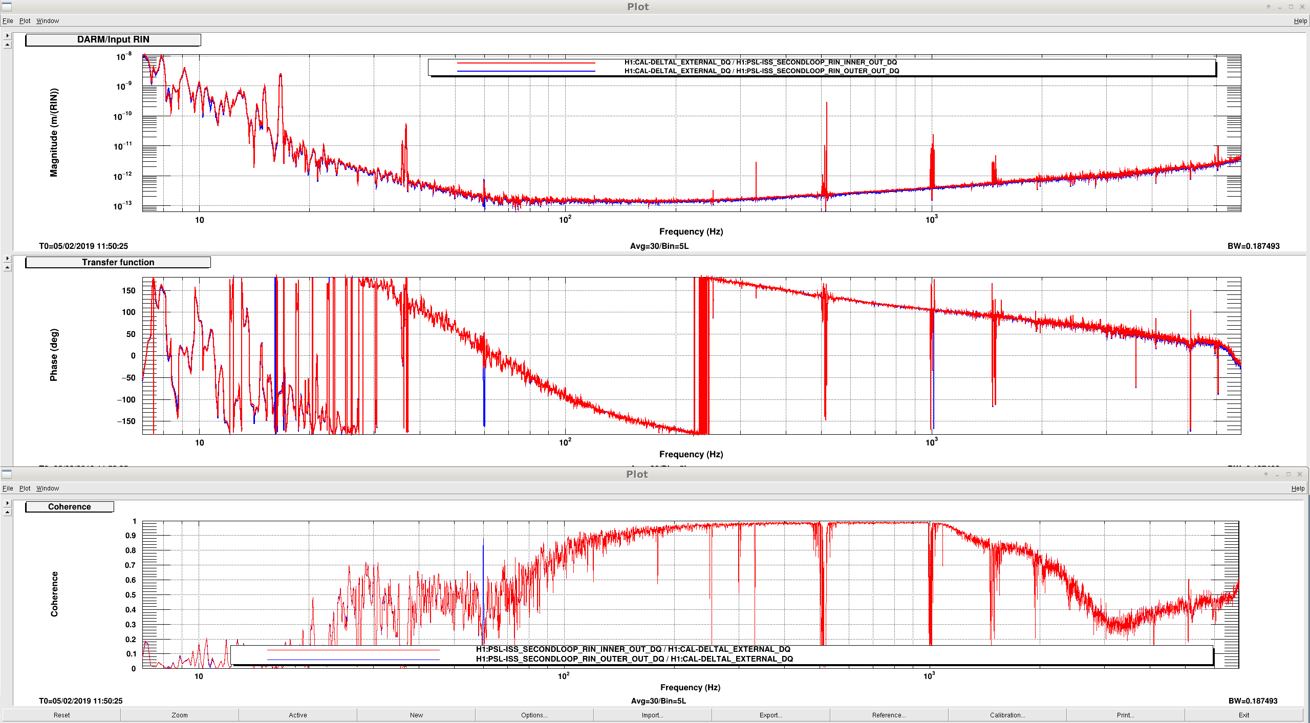
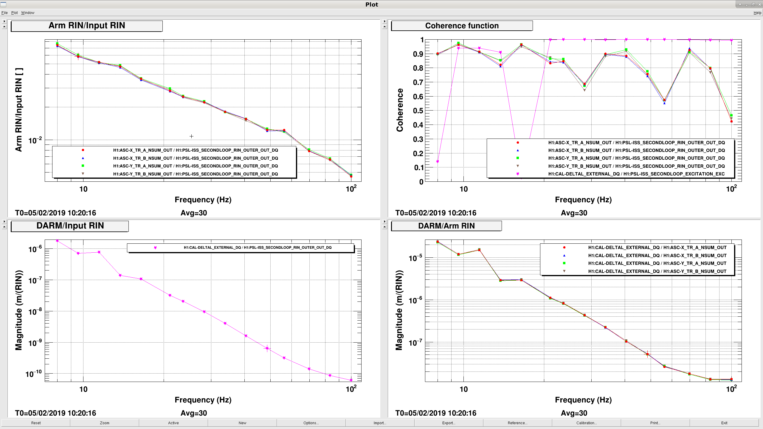
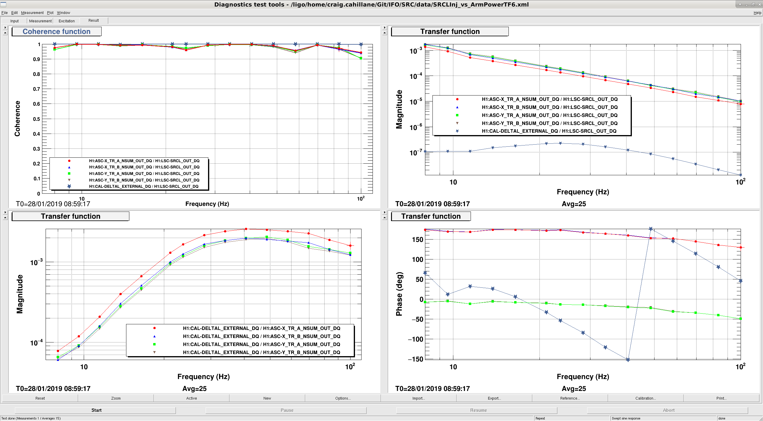
I did a couple of ISS broadband injections and TFs to test the arm power and intensity noise.  I attached the TF template.  Some notes:
- Our ambient input RIN is ~10-8, according to ISS OUTER RIN.
- DARM is limited by the ISS at high frequency (~2k on).  DARM is not limited by the ISS anywhere else.
- Arm RIN/Input RIN goes like f-1 as expected.  
- DARM/Input RIN goes like f-5 according to my TF measurement, and not like f-3.  I do not yet understand this, I would have predicted -3, with -1 from the CARM pole filtering of the Input RIN, and -2 from the compliance of the quads coupling due to radiation pressure effects.
- DARM/Arm RIN goes like f-4.  
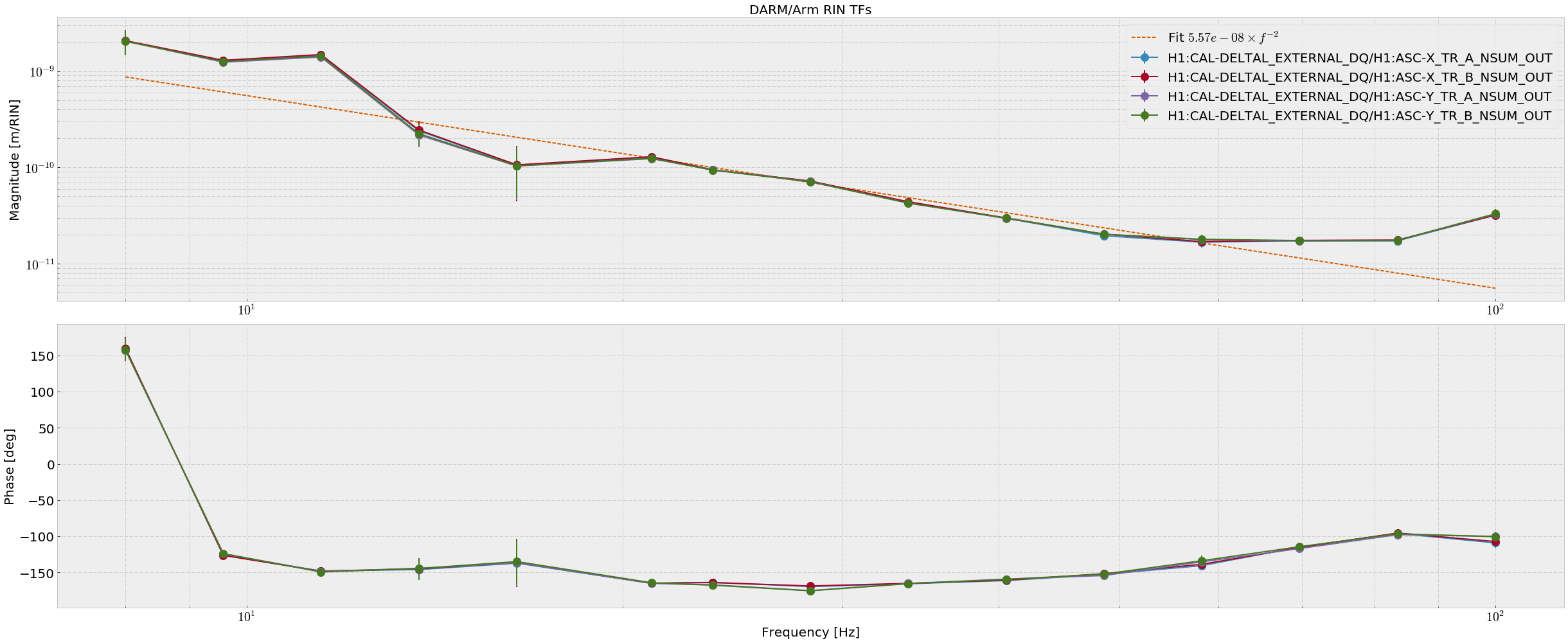
- All the DARM/Arm RIN TFs seem to be nearly the same magnitude.  Some fits must be applied to be able to really tell.
- To calibrate I used the DARM FOM calibration for DARM meters, and found the average value of the Arm QPDs and divided by them.  I assumed that ISS OUTER RIN was already calibrated.

While doing some of these injections I excited ETMX mode 9.  I ran ENGAGE_ALL_DAMPING in the violin mode guardian, this worked.
Images attached to this report
Non-image files attached to this report
Comments related to this report
craig.cahillane@LIGO.ORG - 03:50, Wednesday 06 February 2019 (46813)
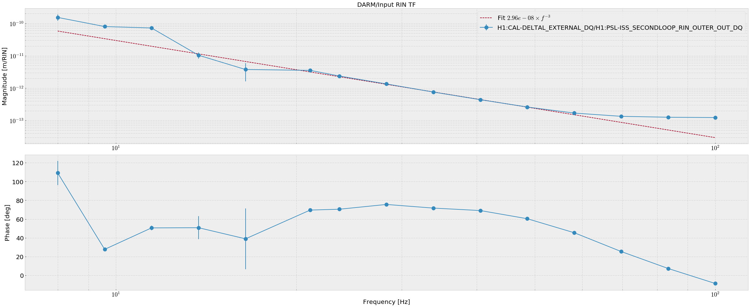
I've found the error in the above results.  The DARM calibration stored in the DTT templates was incorrect, or at least very different from Keita's stopgap calibration from January 2019.

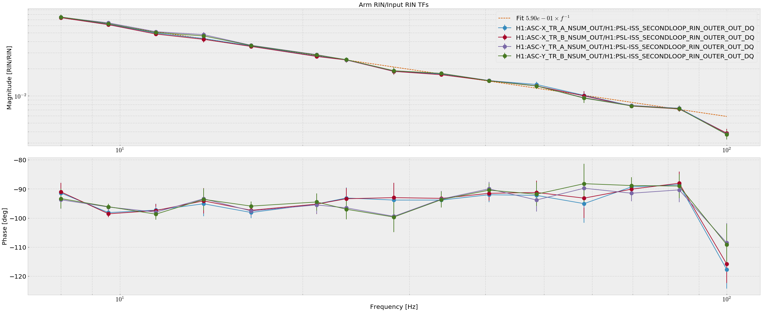
Using Keita's DARM calibration I got sensible results, i.e. DARM/Input RIN goes like f-3, and DARM/Arm RIN goes like f-2.

Attachment one shows DARM/Input RIN.  The results agree pretty well with Gabriele's simulation, within a factor of two (At 30 Hz, my measurement gives 1.1e-12 m/RIN while Gabriele predicts around 7e-13 m/RIN)  I am not sure how Gabriele has defined DARM, I have used Keita's stopgap which assumes DARM = Lx-Ly.

If we trust the equation from alog 46759, and my by-eye fits here of Arm RIN/Input RIN and DARM/Input RIN, we can calculate the differential arm power:

Δ Parm = 2 π2 m c α / β = 11.9 kW
where
α is the DARM/Input RIN f-3 fit coefficient = 3e-8 m/RIN, and
β is the Arm RIN/Input RIN f-1 fit coefficient = 5.9e-1 RIN/RIN.

If we assume that my arm power calculations were correct of 143.0 kW of average arm power, and that the 8% difference is real, we would get 143.0*0.08 = 11.4 kW
Images attached to this comment
H1 ISC
sheila.dwyer@LIGO.ORG - posted 16:24, Monday 04 February 2019 - last comment - 18:10, Monday 04 February 2019(46778)
glitches in ALS X arm, fiber bypass test

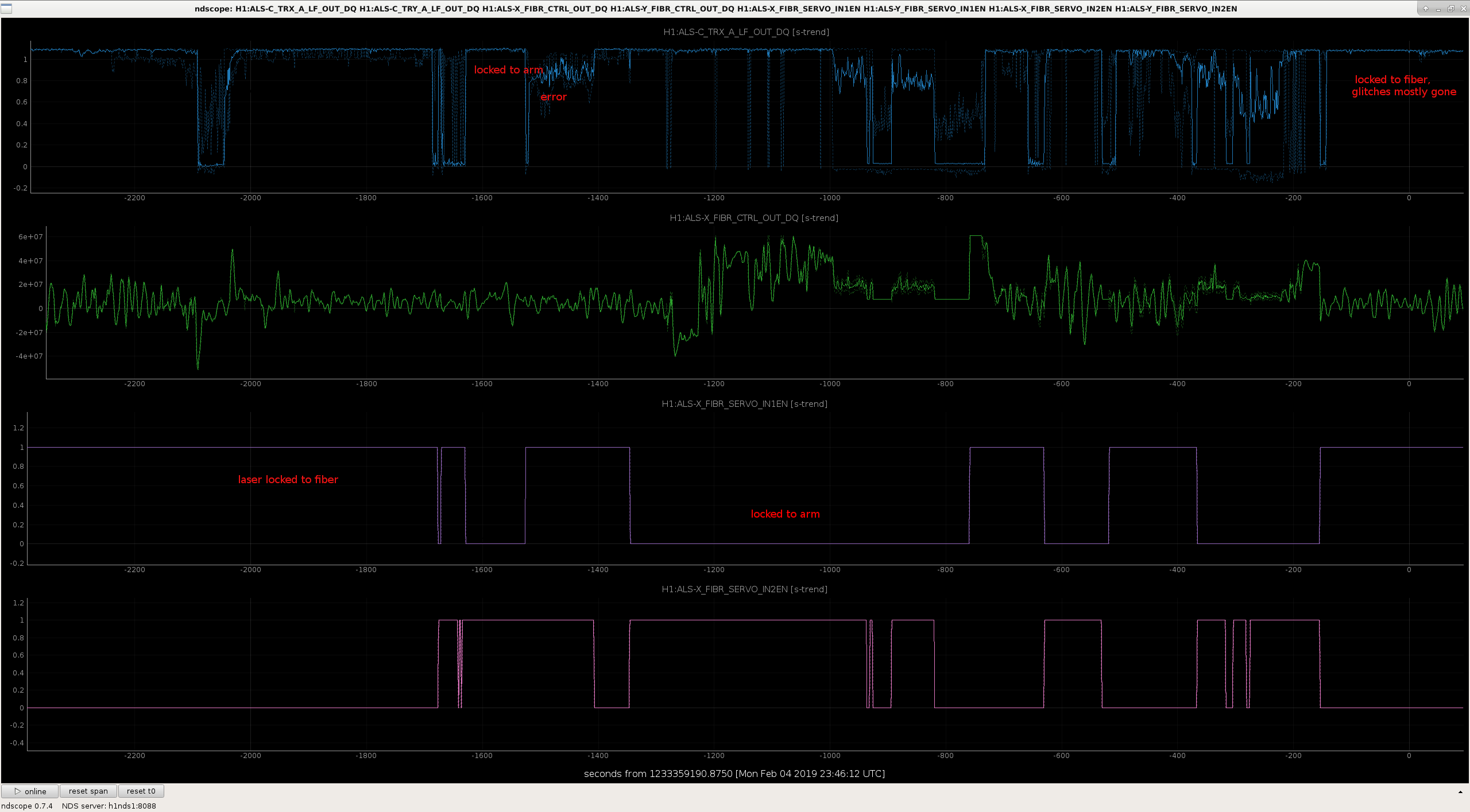
today it is snowing, and we have been having ALS glitches in the X arm for the last 45 minutes or so.  

We wrote a quick script to transition the green lock to the configuration where the fiber is bypassed, and switched back and forth a few times.  The attached text file can just be copied and pasted into a guardian shell, to either transition to the bypassed configuration or back to the normal configuration, you will also need to change the guardain request as the text file tells you to.  

In the attached screenshot you can see that when IN1EN is 1, we are locked with the laser to the PLL , and there is some fuzz on the X arm transmission which is a series of small fast glitches if the plot were more zoomed in.  When IN2EN is 1 we are locked directly to the arm, and in the first couple of examples this does seem to be quieter than with the laser locked to the fiber.  There was a time labeled error when we accidentally left both feedback paths on, we can ignore this. 

The arm comes unlocked fairly often when we are locked with the fiber bypassed.  Next time this happens and we have time to work on this we should go the end station and take some time to measure the transfer function of this lock to the arm. 

Images attached to this report
Non-image files attached to this report
Comments related to this report
sheila.dwyer@LIGO.ORG - 18:10, Monday 04 February 2019 (46779)

We have had other difficulties locking today, with the CARM offset reduction. 

Last sunday, after the computer crash we had moved the VCO compensation filter in the TR CARM loop which used to be engaged when we transitioned to TR_CARM to later in the locking sequence, and we never understood why that was necessary.  Today we moved it back to earlier in the sequence and that has improved the stability of the TR CARM loop.  We also have been sometimes manually deceasing the gain in this path a bit to give us more stability through the CARM offset reduction.  We tried to put this into the guardian once, but that didn't work so we have removed it again.

H1 General
yannick.lecoeuche@LIGO.ORG - posted 16:14, Monday 04 February 2019 (46777)
Shift Summary - Day

TITLE: 02/04 Day Shift: 16:00-00:00 UTC (08:00-16:00 PST), all times posted in UTC

STATE of H1: Commissioning

INCOMING OPERATOR: None

SHIFT SUMMARY:


14:40 (6:40) Chris traveling arms to assess tumbleweed buildup

16:00 (8:00) Start of shift

17:45 (9:45) Hugh to EX -- look at anemometer

17:46 (9:46) Terry to Optics Lab

17:55 (9:55) Marc, Fil to Vault -- PEM system calibration

18:04 (10:04) Terry back from Optics Lab

18:12 (10:12) Kyle to MY -- wiring on prototype vacuum equipment

18:18 (10:18) Hugh back from EX

18:34 (10:34) Patrick to MSR

19:07 (11:07) CALEX, CALEY restart

19:13 (11:13) Vanessa to EX, EY, MY

19:43 (11:43) Kyle back from MY

20:00 (12:00) Marc, Fil back from Vault

22:00 (14:00) Nutsinee to LVEA

23:19 (15:19) Nutsinee out of LVEA

00:00 (16:00) End of shift

H1 ISC
daniel.sigg@LIGO.ORG - posted 15:54, Monday 04 February 2019 - last comment - 13:26, Tuesday 05 February 2019(46775)
OMC model changes

In preparation for adding the second HV driver to the OMC PZT driver chassis, the OMC model was updated.

  1. Remove all references to the old software trigger infrastructure.
  2. Add a new filter module PZT3 to apply the bias.
  3. Use the previous "fast shutter trigger" channel as the new output (chn 3 on the DB9 DAC channel).
  4. Added new readback channels for DC & AC. These are chns 3 & 4 on the DB9 cable coming from the DC PD interface chassis.
Comments related to this report
daniel.sigg@LIGO.ORG - 13:26, Tuesday 05 February 2019 (46792)

Model has been restarted with new channels.

H1 SQZ (SQZ)
nutsinee.kijbunchoo@LIGO.ORG - posted 17:01, Thursday 31 January 2019 - last comment - 16:12, Monday 04 February 2019(46730)
SQZ Pump power intensity servo is working (again)

Daniel, Nutsinee

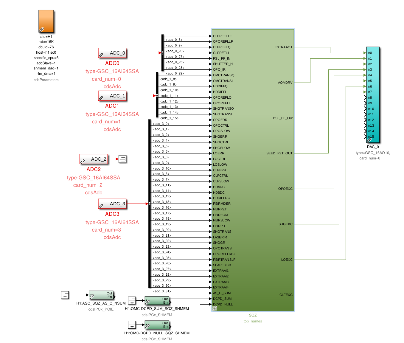
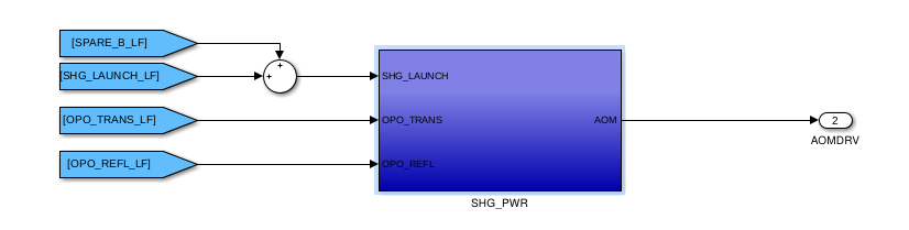
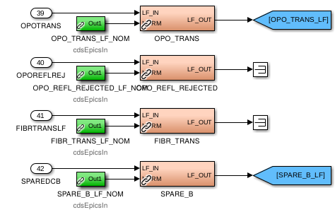
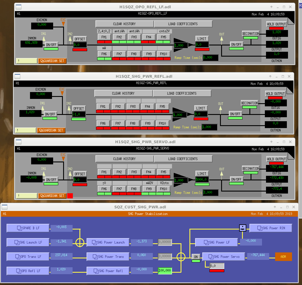
We had been using OPO common mode board for the intensity servo until we swapped the scheme (now the OPO CM board is actually used to lock the OPO). The servo is now all digital with a UGF of 200Hz. H1:SQZ-OPO_TRANS_LF_NOM has to be set to 1. The output (2nd from the left of SQZ rack U16) goes through a 450 Ohms resister and to the IFR that drives the AOM.

Images attached to this report
Comments related to this report
nutsinee.kijbunchoo@LIGO.ORG - 16:12, Monday 04 February 2019 (46776)

We found a filter that wasn't supposed to be on (an anti-whitening for a build-in whitening filter inside a PD, which OPO refl doesn't have). Fixed the mW2V gain (now 40) and the UGF of the intensity loop is now 100Hz. It no longer glitch when we turn the loop on. We also found that the whitening filter was turned off, which worked for the analog setup we used to have.

Images attached to this comment
H1 AOS (ISC)
craig.cahillane@LIGO.ORG - posted 17:42, Tuesday 29 January 2019 - last comment - 20:49, Monday 04 February 2019(46683)
What is the arm power 2
On January 8th I tried to measure the average arm power by dithering SRCL.  Last night I did it again, this time with better TFs taken simultaneously.

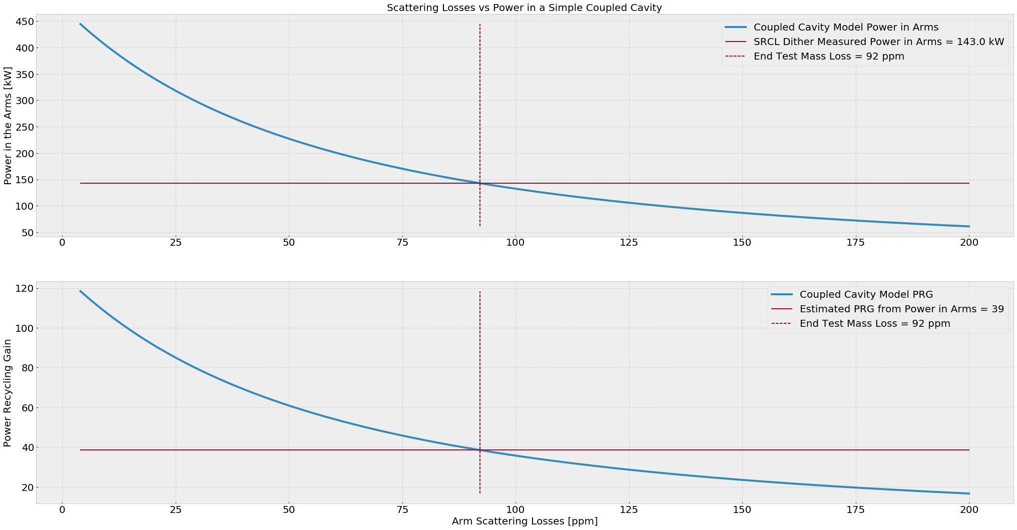
Average Arm Power = 143.0 +- 5.8 kW

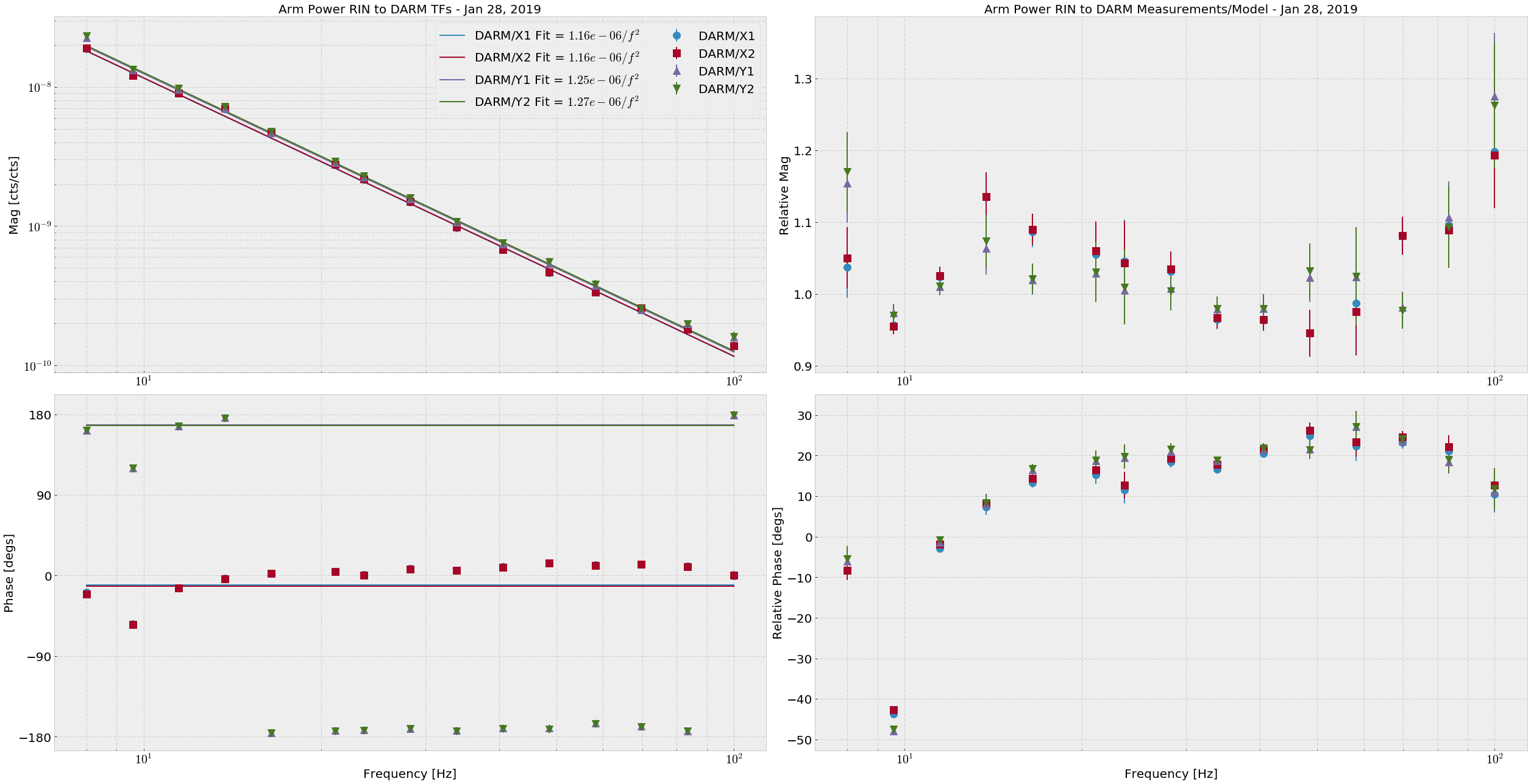
This time I directly fit each of the four Arm Trans QPD RINs (H1:ASC-{X,Y}_TR_{A,B}_NSUM_OUT_DQ) to DARM (H1:CAL-DELTAL_EXTERNAL_DQ), then fit a 1/f2 (attachment one).  The DARM calibration used was the stop gap made by Keita.  The average powers for the RIN calculation are as follows, and are good to +- 300 cts:
Arm Trans QPD counts
XA      145658
XB      191409
YA      207723
YB      221769


This time the math is simpler: 
P_arm = DARM/ArmTransRIN Fit × π2 × m × c


If we look at the different in the arm trans RIN response between the arms, and say that the RIN we see is entirely due to radiation pressure in the arms, we get (DARM/Y)/(DARM/X) = X/Y = 1.08, meaning there may be 8% more light in the X arm than the Y arm.  EDIT: It is actually the Y arm with 8% more light than the X arm.

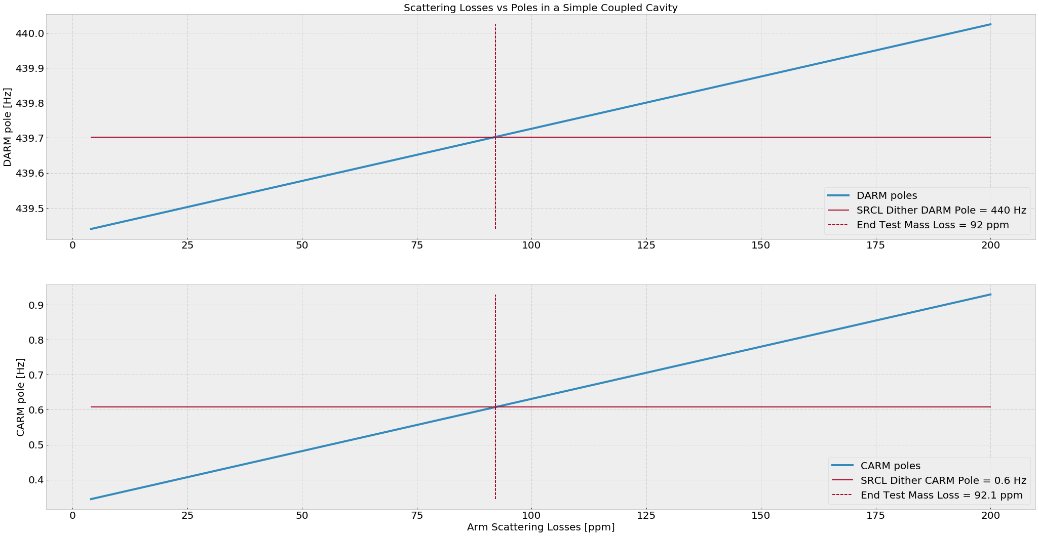
If we calculate the simple power recycling coupled cavity, I find that the estimated average ETM scatter losses are around 92 ppm and the estimated PRG here is 39.  (attachment three)

The measured value of PRG at the time of the measurement is 41.8, and the true input power was 26.5 W (requested was 30W).  If we take these numbers to be true, then our arm gain according to the SRCL dither is 258.
Images attached to this report
Comments related to this report
gabriele.vajente@LIGO.ORG - 15:04, Tuesday 29 January 2019 (46694)

Some simulation work related to this measurement.

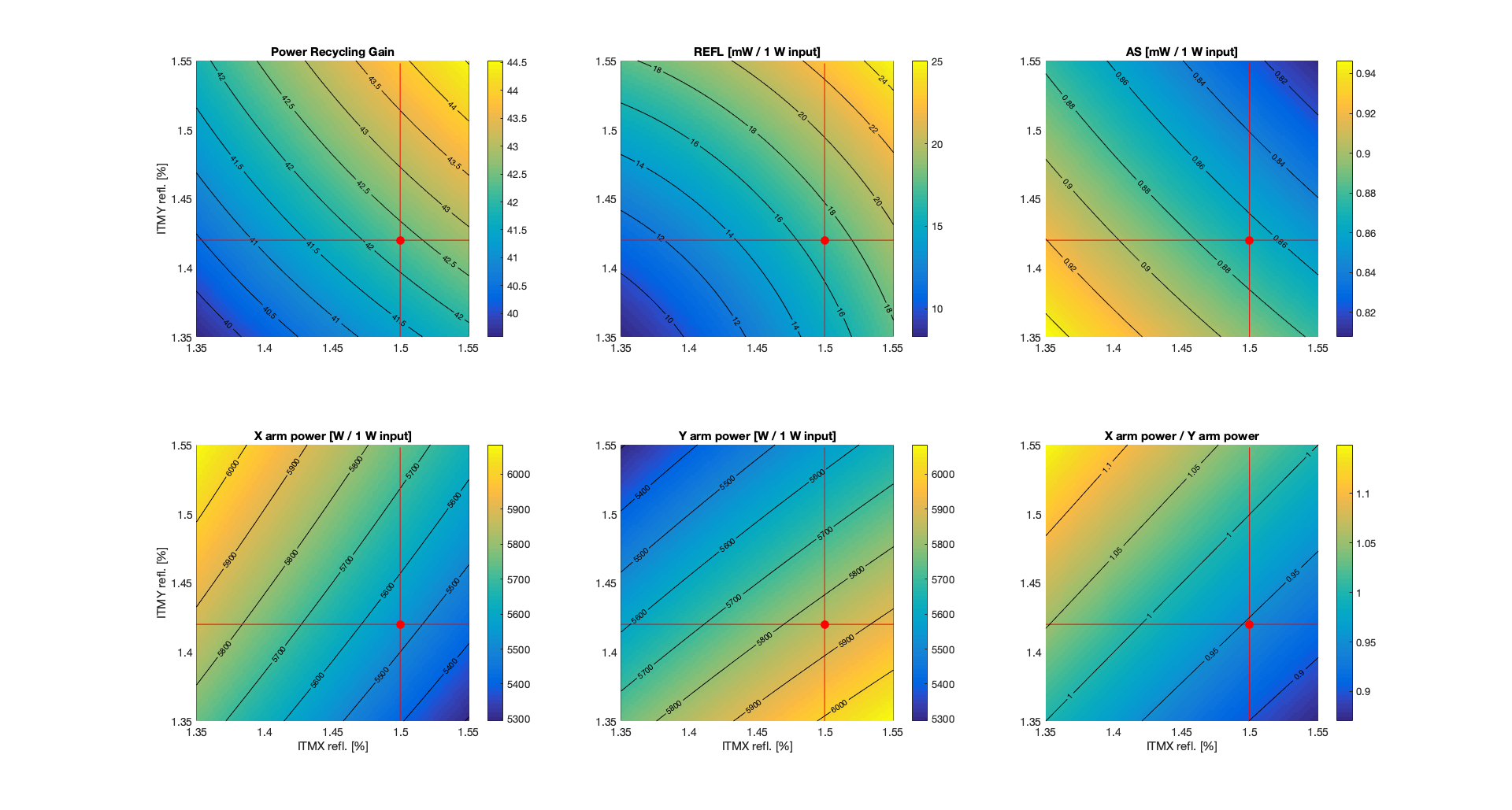
From galaxy, I find that LHO's ITMX (ITM07) has a reflectivity of R_ITMX = 1.50%, while LHO's ITMY (ITM11) has a reflectivity of 1.42%. So there's quite an imbalance there.

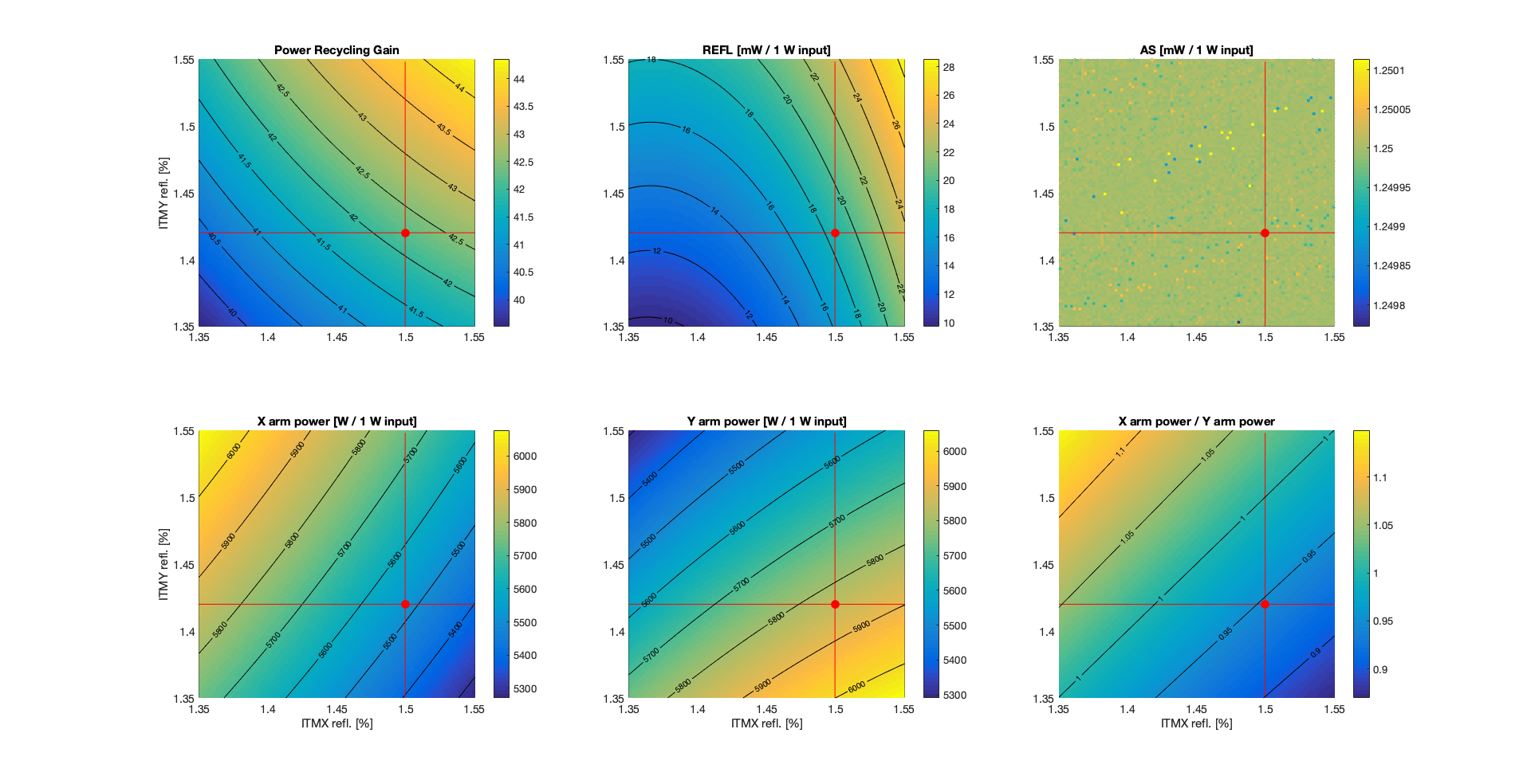
I set up a simple simulation, using only the TEM00 mode, so without including any mismatch. Each arm has about 92 ppm of total round trip losses, following Craig's estimate. The first plot below shows some powers as a function of the two ITM reflectivities. 


The red dot represent the nominal condition, which gives, for 1 W input power

PRG = 42.3
REFL = 17 mW (carrier only, TEM00, perfect matching)
AS = 0.9 mW (carrier only, TEM00m, perfect matching, nominal DARM offset of 1.2e-11 m
XARM = 5536 W
YARM = 5848 W
X/Y = 0.946 [more power in Y arm than X arm]

So there is more power in the Y arm than in the X arm, as one would expect since ITMY has higher reflectivity, so that the Y arm has higher finesse.

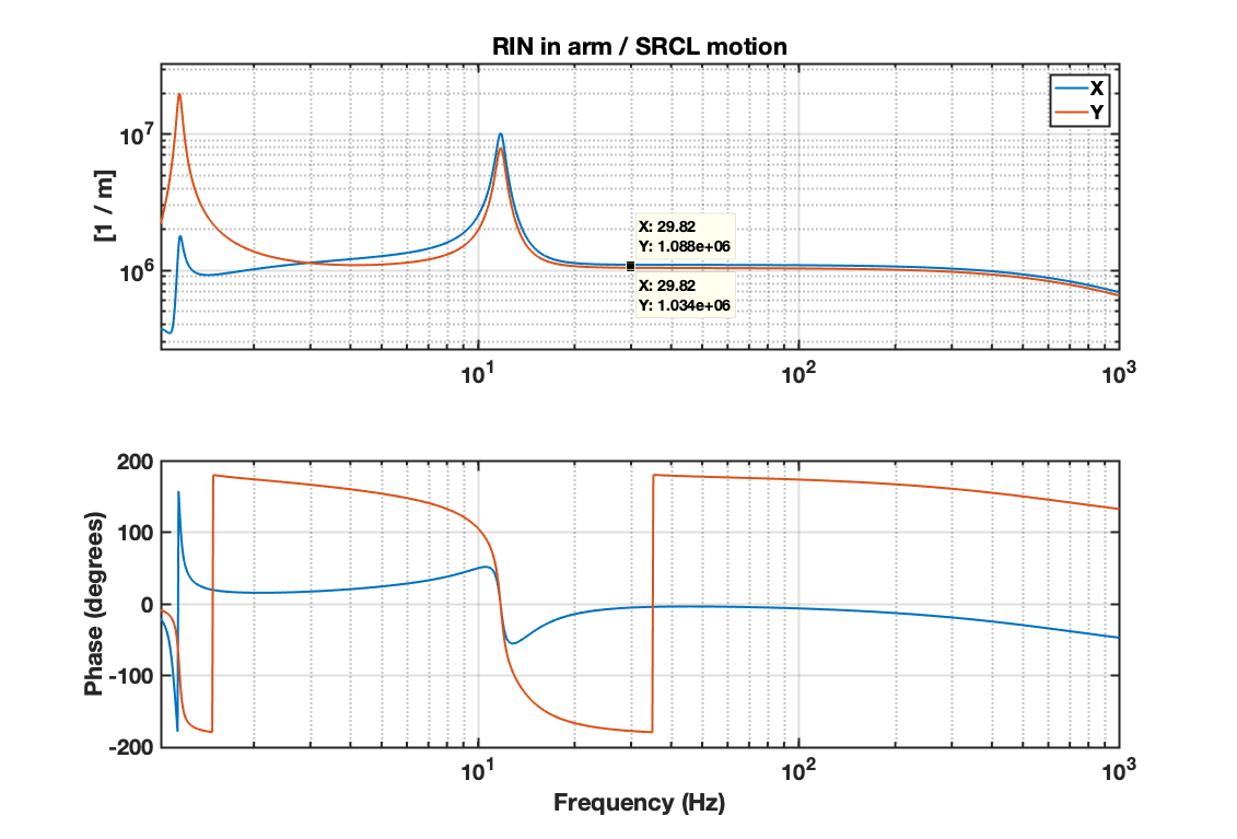
I also tried to reproduce more closely Craig's SRCL dither measurement. So in simulation, I computed the transfer function from SRCL motion to the RIN as measured in transmission of both arms. The plot below shows the simulated transfer functions RIN_ARM / SRCL for X and Y:


The numerical values are

RIN_X / SRCL_z = 1.088e6 /m
RIN_Y / SRCL_z = 1.034e6 /m

so (RIN_X / SRCL_z ) / (RIN_Y / SRCL_z) = 1.052. This is the ratio of powers, since the simulated transfer functions from SRCL to powers are equal for both X and Y, so the transfer functions to RIN are scaled by the inverse of the power. 

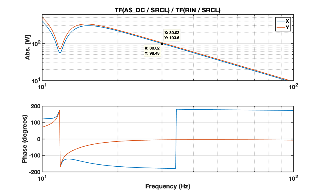
Craig's measurement is actually the transfer function DARM / RIN while injecting on SRCL. In simulation, I used the AS port power as a proxy for DARM and computed the transfer functions TF(AS_DC / SRCL) and TF(RIN / SRCL). Then the equivalent of Craig's DARM / X and DARM / Y should be, at 30 Hz,

TF(AS_DC /  SRCL) / TF(RIN_X / SRCL) = 98.4 W
TF(AS_DC /  SRCL) / TF(RIN_Y / SRCL) = 103.6 W

and the frequency dependency is shown in the plot below (1/f^2 as expected).


So the equivalent of Craig's ratio (DARM / Y) / (DARM / X) should be 

[ TF(AS_DC /  SRCL) / TF(RIN_Y / SRCL) ] / [ TF(AS_DC /  SRCL) / TF(RIN_X / SRCL) ] = 103.6 / 98.4 = 1.053

which is greater than one as in Craig's measurement, but corresponds to the ratio POWER_Y / POWER_X. 

So the conclusion from my simulation is that the ITM different reflectivities gives a ratio of TF (as measured by Craig) greater than 1, which corresponds to higher power in the Y arm than in the X arm (the opposite of what Craig's concluded...)


Images attached to this comment
craig.cahillane@LIGO.ORG - 17:17, Tuesday 29 January 2019 (46698)
I didn't know that the ITMs were not the same reflectivity.  This is absolutely mind-blowing information.
I reported higher arm power in the Y arm before, from the HEPI measurement.  
The RIN/SRCL TF corresponds to Equation 12 here.  It is not dependent on the arm power at all, but rather the optical response γ of each arm to the SRCL dither.
Also, the DARM/RIN TF in Equations 20 and 21 also indicate that DARM/RIN = 4*Parm/(m c ω2), so I made a mistake last night.
gabriele.vajente@LIGO.ORG - 20:41, Tuesday 29 January 2019 (46700)

Good that the measurement and the prediction agree that there is more power in Y than in X.

Now we have to figure out why the measurement gives 8% imbalance while from the ITM reflectivities we only get 5%.

gabriele.vajente@LIGO.ORG - 16:50, Wednesday 30 January 2019 (46710)

Updated simulation: 

  1. added higher order modes (n+m<=10), measured test mass radii of curvature
  2. locked DARM to have an AS power that corresponds to 20 mA at 26 W input power (1.25 mW on the OMC transmission for 1 W input)

No change in the conclusions. Same imbalance of the arm powers as before (about 5%) 


Images attached to this comment
gabriele.vajente@LIGO.ORG - 09:43, Thursday 31 January 2019 (46720)

Adding the substrate lenses do not change significantly the power imbalance. 

ITMX: static lens -310km, thermal lens +770km
ITMY: static lens +570kn, thermal lens +350km

gabriele.vajente@LIGO.ORG - 14:46, Friday 01 February 2019 (46749)

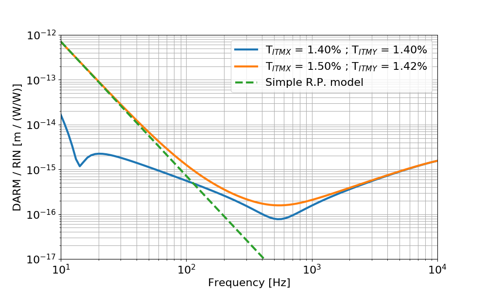
Follow up to the discussion at today's commissioning call.

I computed the transfer function from laser relative intensity noise at the IFO input (called rin below) to DARM (calibrated in meters). 

The input power is 26 W, and the round trip losses are adjusted to get a recycling gain of about 42. In the blue trace below, the two ITMs have the same reflectivity, equal to the nominal value of 1.4%. In the orange trace the two ITMs have different reflectivities, ITMX = 1.50% and ITMY = 1.42%, from the measured values from galaxy. This is the same configuration used in the other simulations, that gives a 5% power imbalance. 

The dashed green curve is a simple radiation pressure model according to the equation below:


where RIN_arm / RIN_input is basically the double cavity pole (since input RIN is filtered by this transfer function. I used the simulated result), Delta P is the DC power difference in the arms ( Y - X = 7.7 kW) and m is the mirror mass. This matches quite well the low frequency simulation.


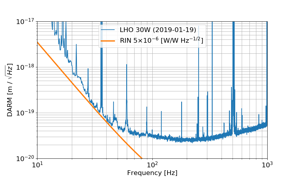
Using the simulated transfer function I can see what level of RIN at the IFO input would limit the sensitivity. It turns out that one needs a RIN of about 5e-6 (W/W)/rHz. 


Images attached to this comment
gabriele.vajente@LIGO.ORG - 11:18, Monday 04 February 2019 (46759)

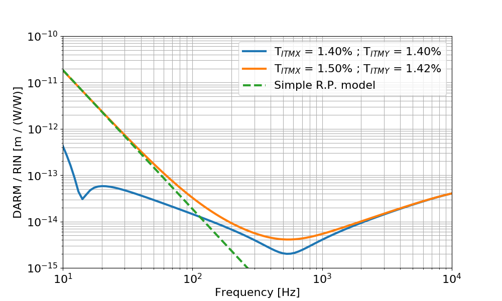
I found a mistake in my previous RIN simulation (many thanks to Matt Evans for spotting the inconsistency). Here's the correct results and plots.

Follow up to the discussion at today's commissioning call.

I computed the transfer function from laser relative intensity noise at the IFO input (called rin below) to DARM (calibrated in meters). 

The input power is 26 W, and the round trip losses are adjusted to get a recycling gain of about 42. In the blue trace below, the two ITMs have the same reflectivity, equal to the nominal value of 1.4%. In the orange trace the two ITMs have different reflectivities, ITMX = 1.50% and ITMY = 1.42%, from the measured values from galaxy. This is the same configuration used in the other simulations, that gives a 5% power imbalance. 

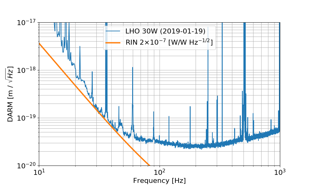
The dashed green curve is a simple radiation pressure model according to the equation below:


where RIN_arm / RIN_input is basically the double cavity pole 0.6Hz/fr (since input RIN is filtered by this transfer function), Delta P is the DC power difference in the arms ( Y - X = 7.7 kW) and m is the mirror mass. This matches quite well the low frequency simulation.

Using the simulated transfer function I can see what level of RIN at the IFO input would limit the sensitivity. It turns out that one needs a RIN of about 2e-7 (W/W)/rHz


Images attached to this comment
matthew.evans@LIGO.ORG - 15:35, Monday 04 February 2019 (46772)

Doesn't this 2e-7 /rtHz RIN seem dangerously close to the measured value at 30Hz?

sheila.dwyer@LIGO.ORG - 20:49, Monday 04 February 2019 (46780)

The intensity noise projection in the noise budget is made by injecting into the ISS second loop.  It shows that the intensity noise is not close to DARM.  45828


LHO VE
chandra.romel@LIGO.ORG - posted 10:39, Friday 18 January 2019 - last comment - 13:56, Tuesday 05 February 2019(46527)
GV12 inspection

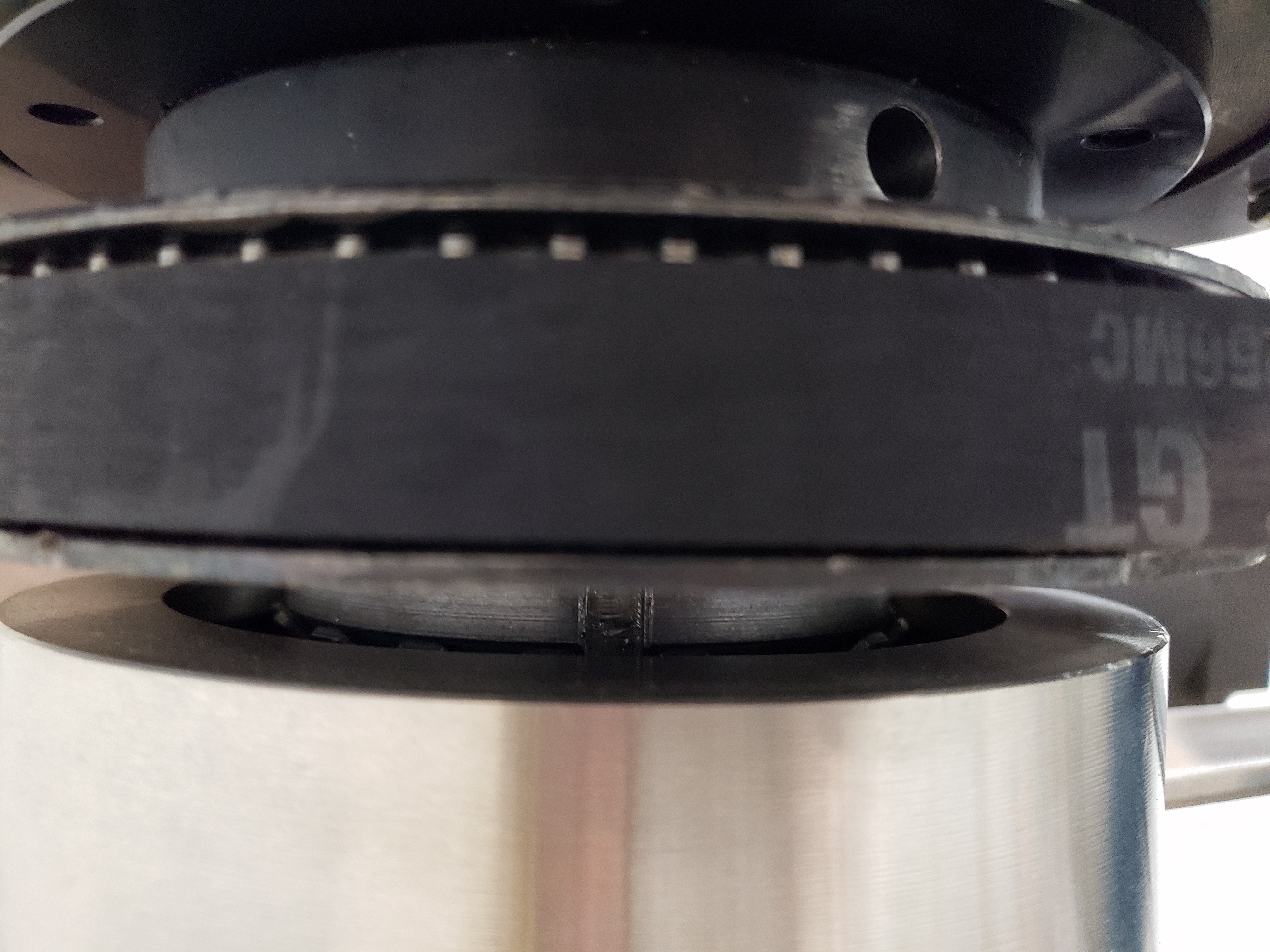
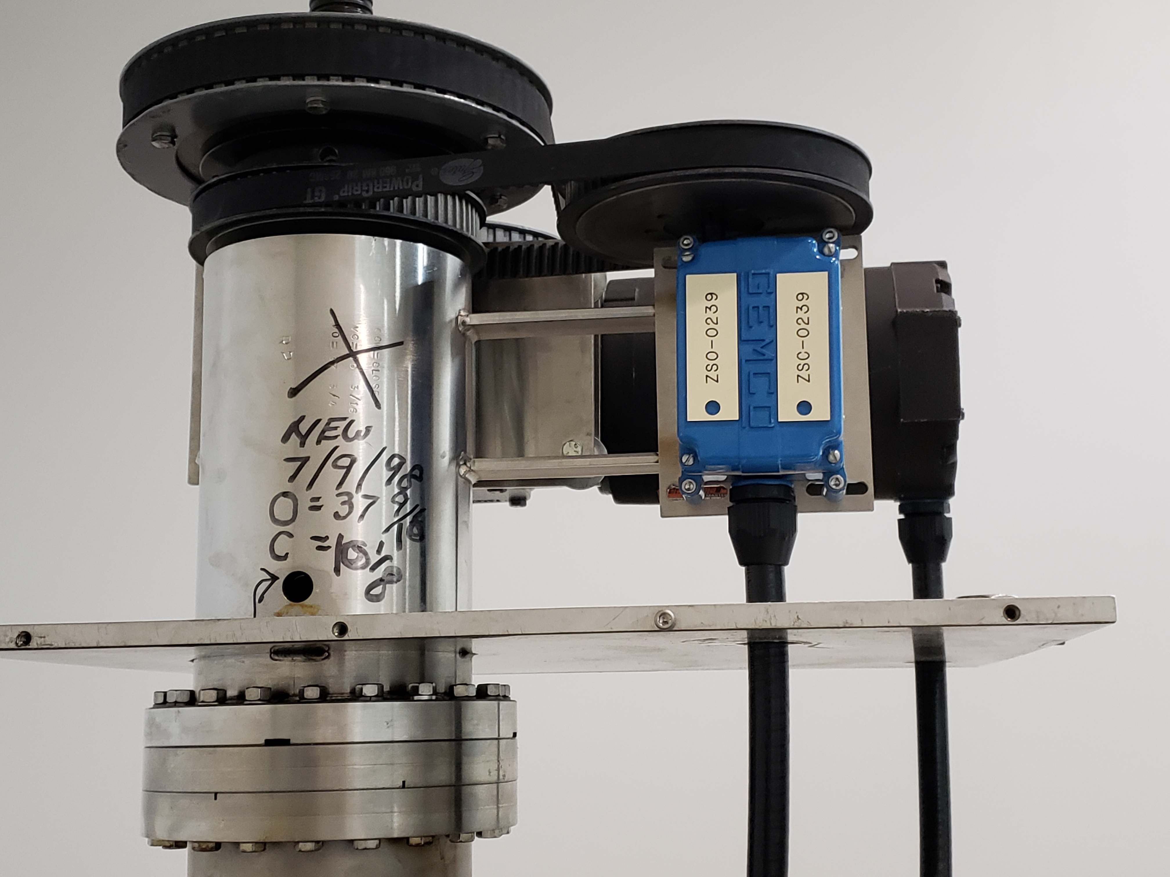
Per Q1800019, I visually inspected H-GV12 on Dec. 19 to verify that the spindle nut and lock washer are present. Was not able to inspect torque setting without fall protection.

Images attached to this report
Comments related to this report
kyle.ryan@LIGO.ORG - 13:56, Tuesday 05 February 2019 (46793)

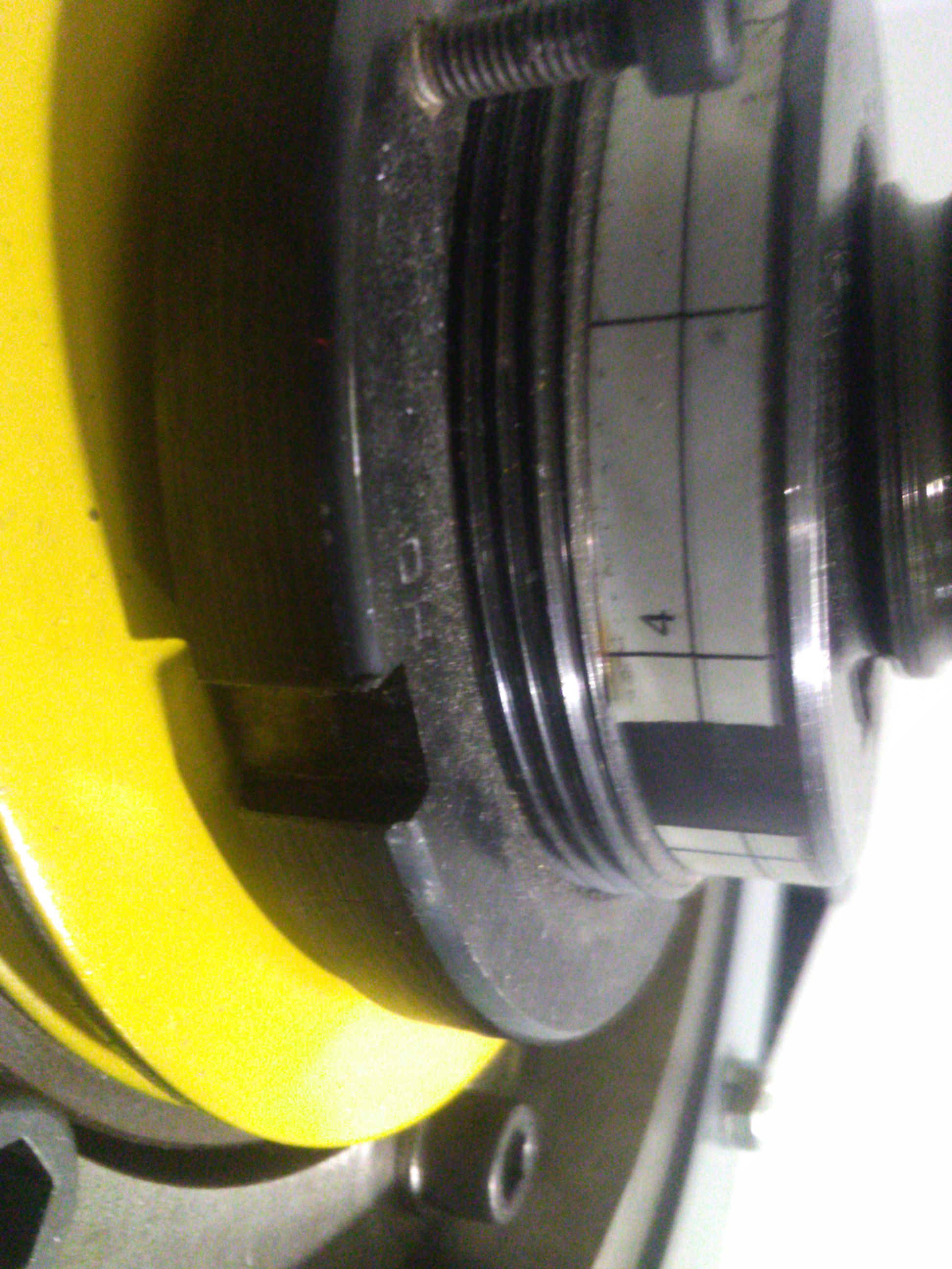
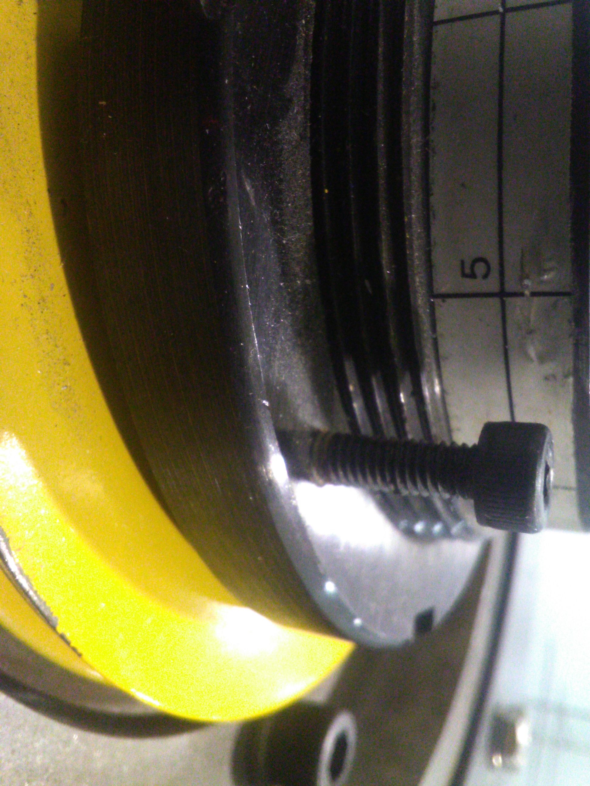
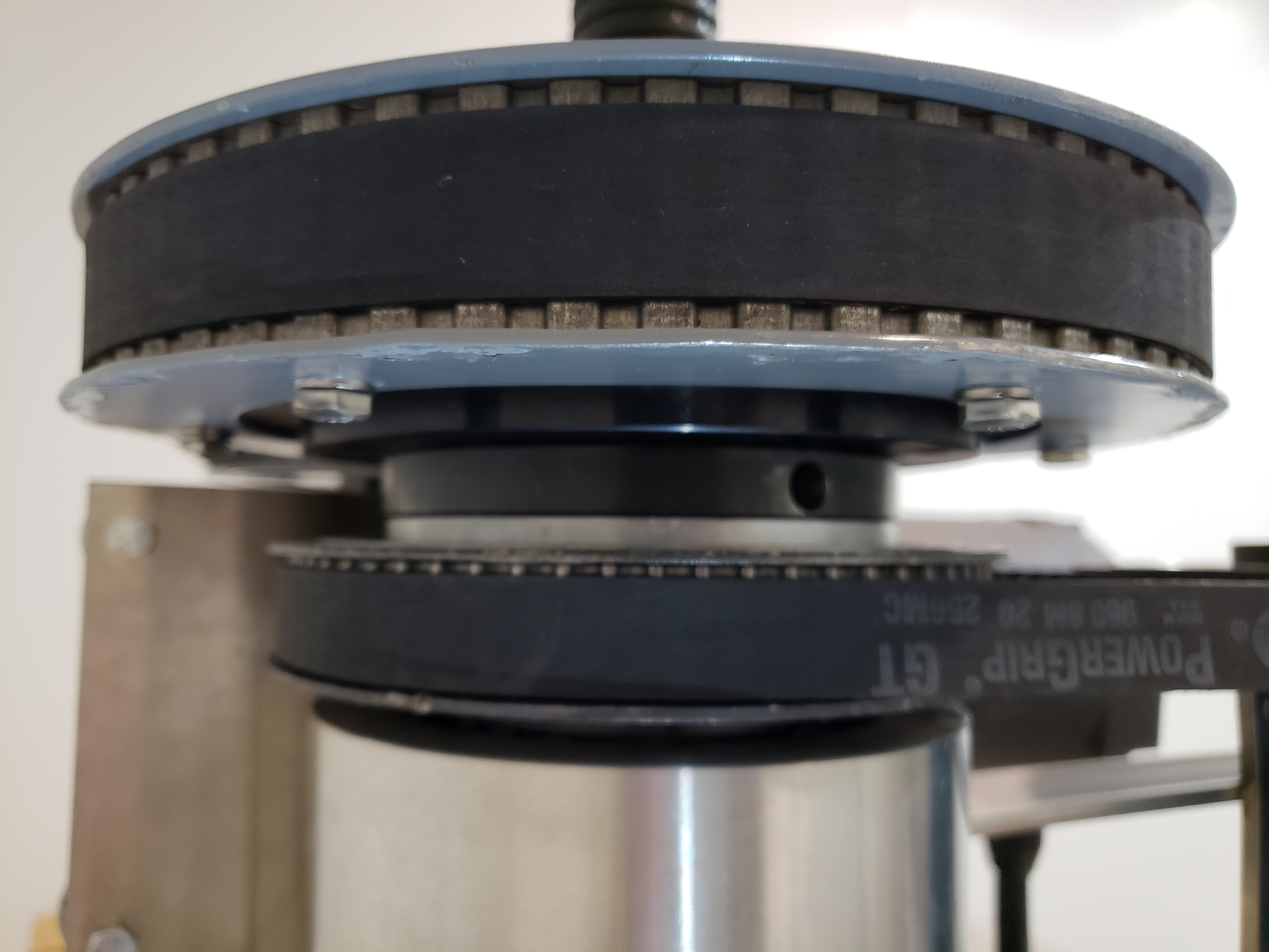
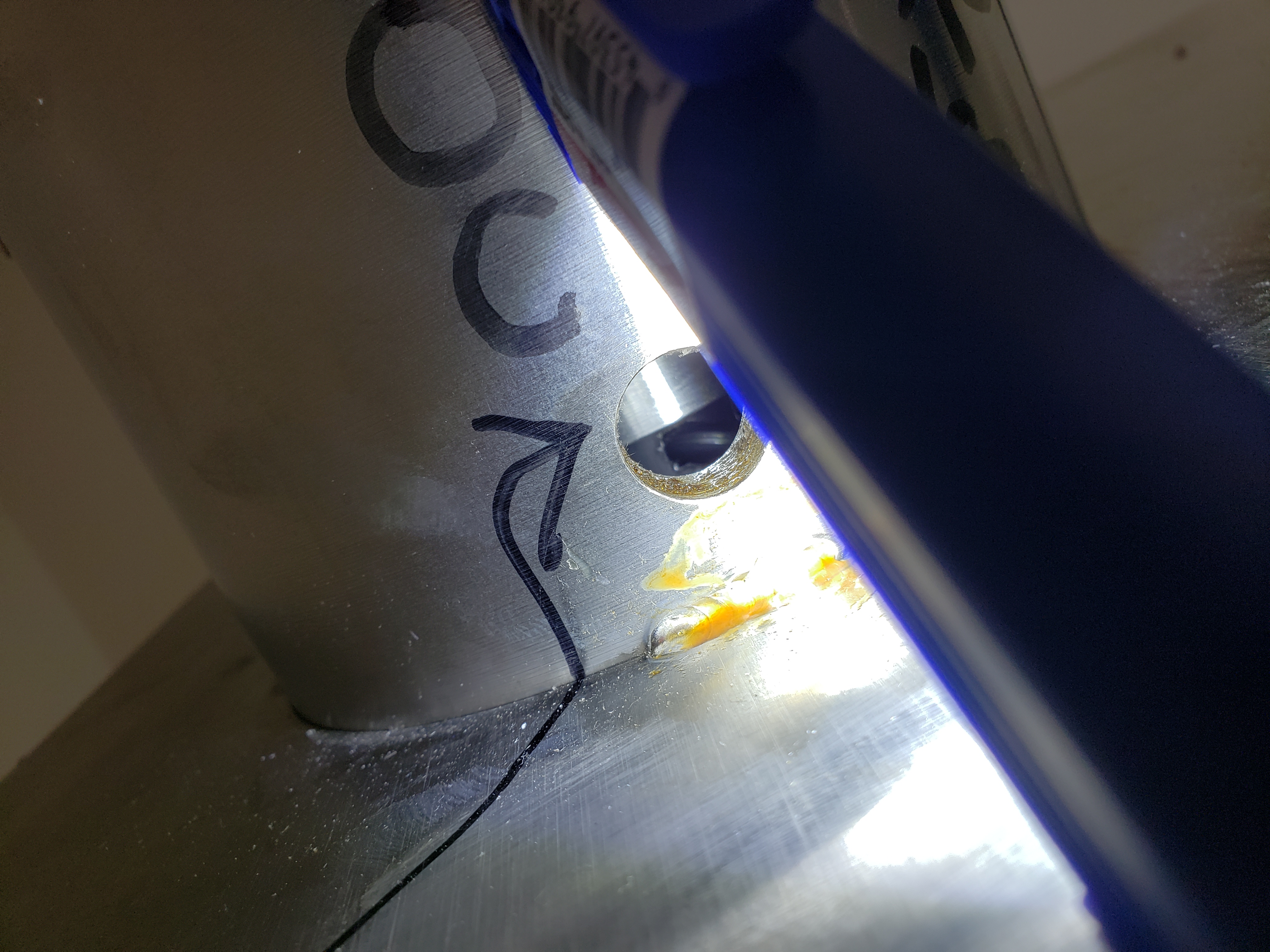
Attached are photos showing the indicated torque pre-load for GV12.  Note that the number of exposed threads may also be important.  

Images attached to this comment
Displaying reports 43221-43240 of 88625.Go to page Start 2158 2159 2160 2161 2162 2163 2164 2165 2166 End