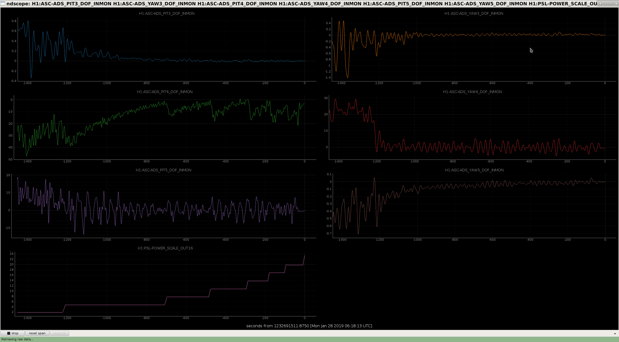
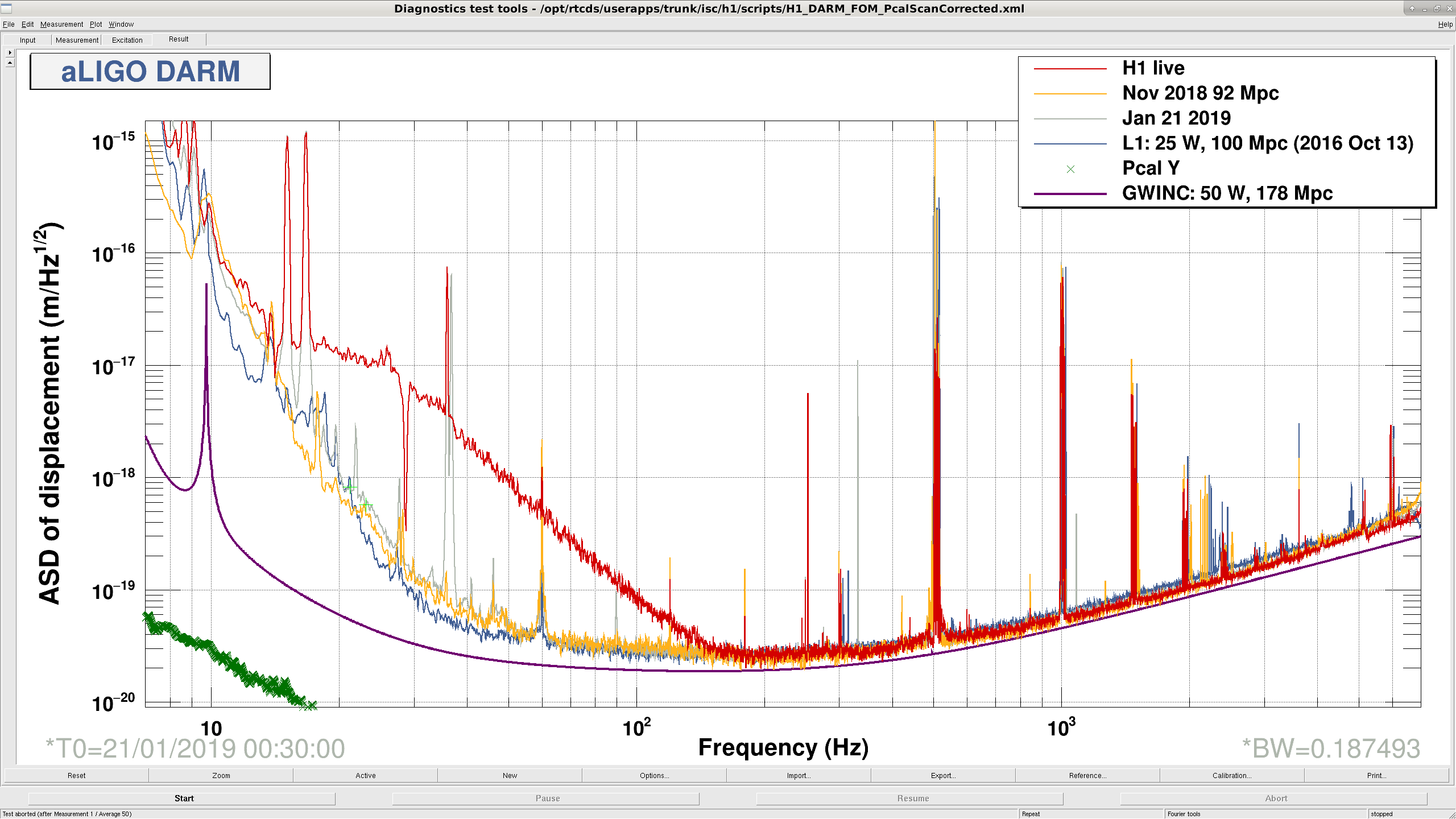
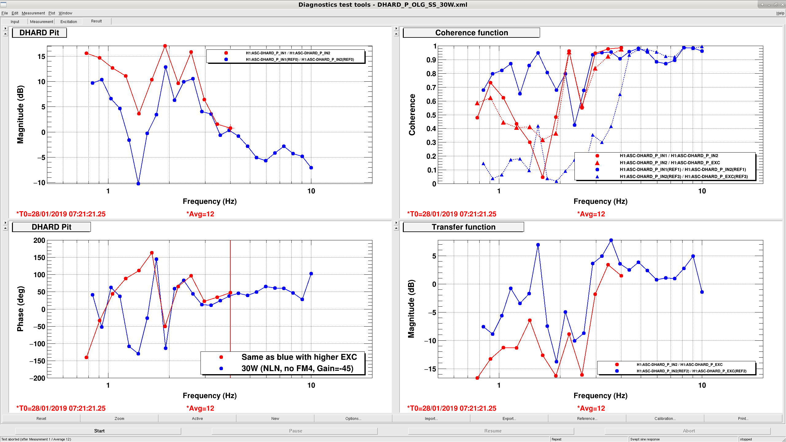
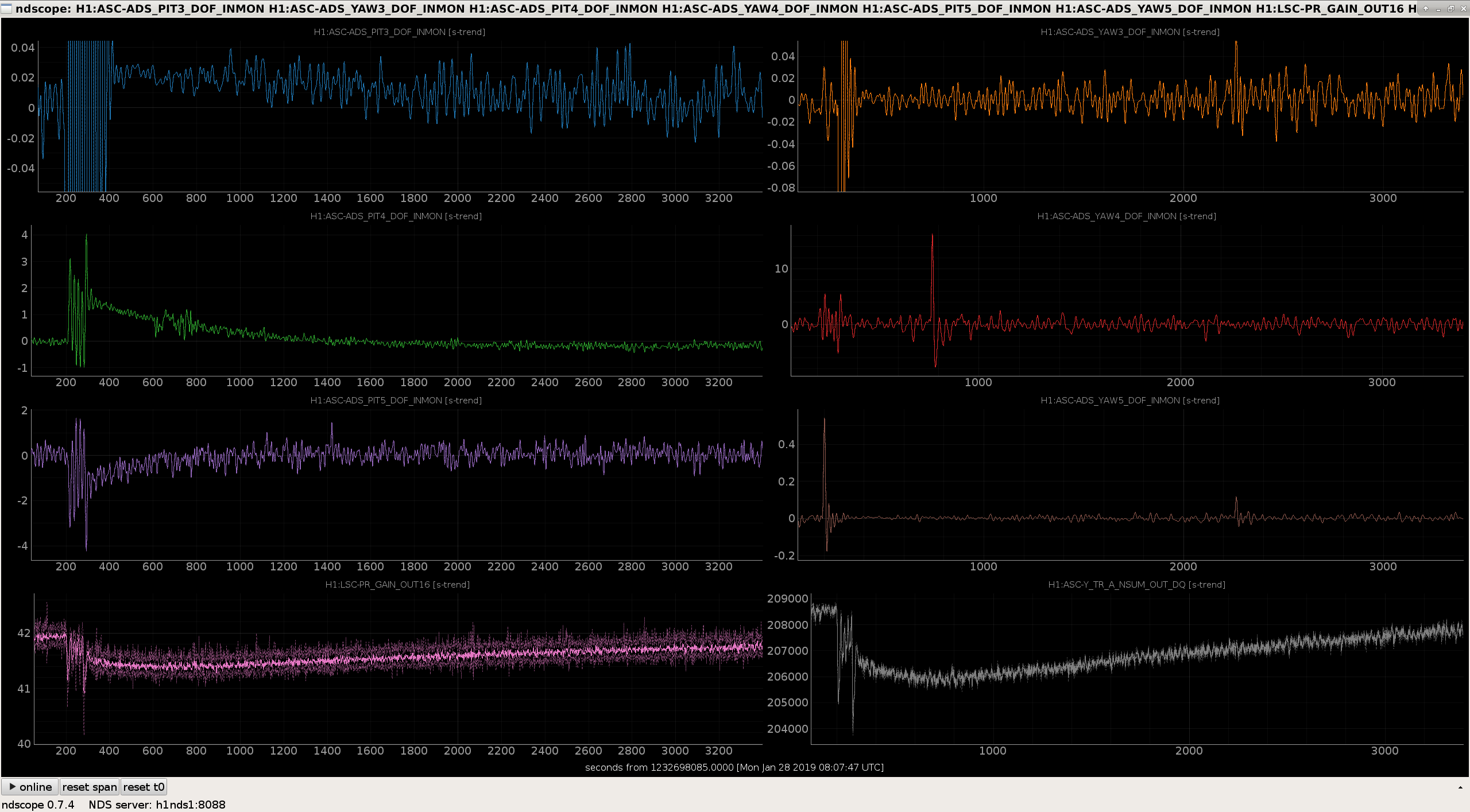
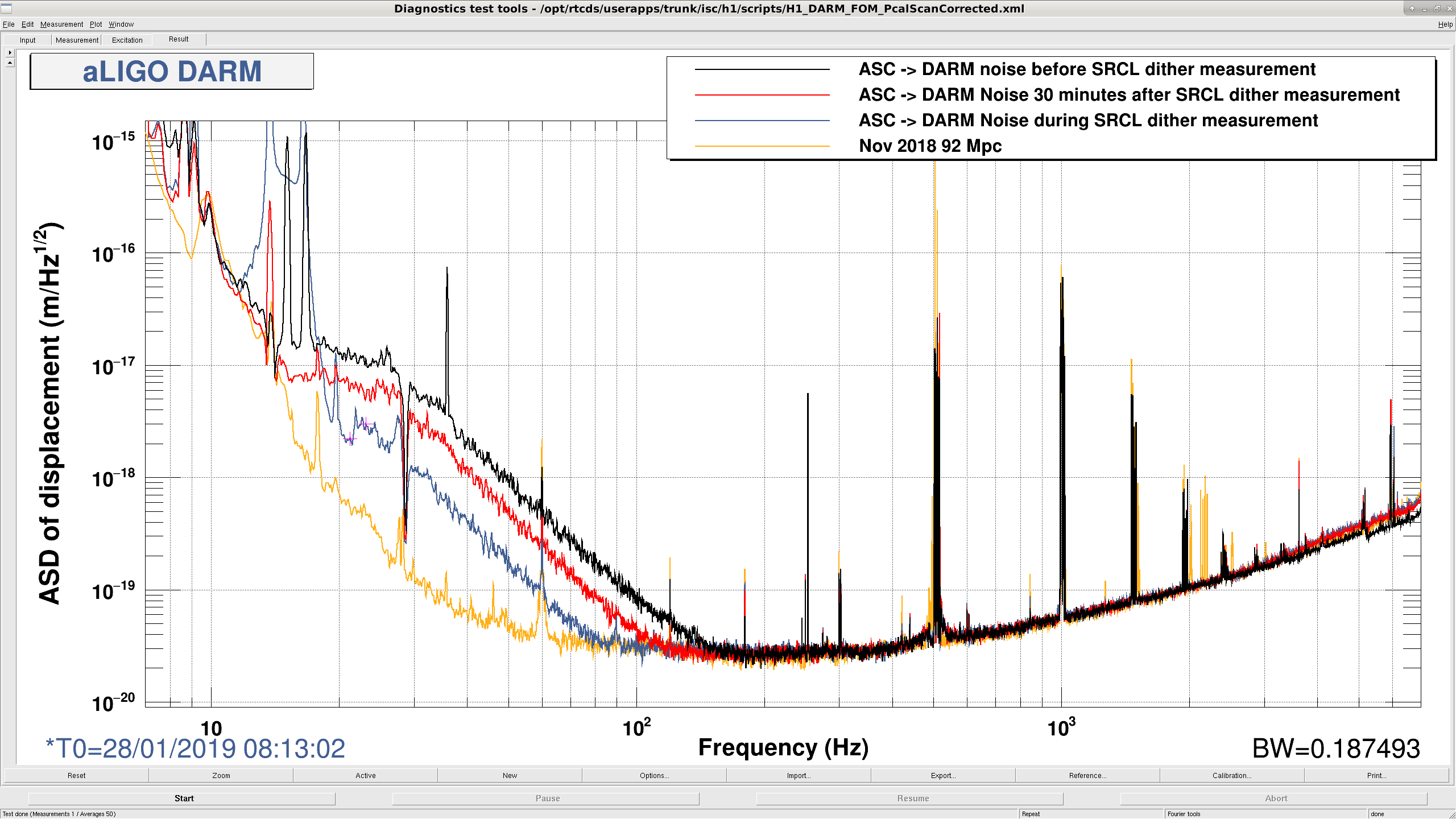
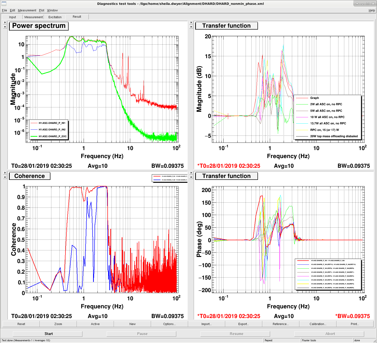
Kara, Craig - We lost lock in LOWNOISE_ASC after engaging DHARD_P FM4, "ELP17", a . Took about 5 mins for the 1 Hz instability to ring up. Will skip in future attempts. - We had problems with losing lock around FIND_IR and ACQUIRE_DRMI due to ALS COMM tidal offloading/noisy DRMI weirdness. Nothing changed in the tidal loop, so I checked the SEI_CONF settings, and all of our HAMs were stuck in ENGAGING_CONFIG_WINDY. Not clear how long it's been that way, likely since the computer crash. I added the SEI_CONF guardian to ISC_GUARDIANS medm screen so that we can see the "not all nodes arrived " warning next time this happens. - Commented out the line about turning on DHARD P FM4, the guardian got to NOMINAL LOW NOISE by itself. Noise was very high and perfectly coherent with DHARD P. (Attachment two) - INCREASE_POWER was taking upwards of 12 minutes waiting for the dither loops to converge. At each 4 watt step in power, we wait for the dither loops to converge to avoid locklosses, and the dither loops' bandwidth is on the order of 0.1 Hz. The pitch of the X-arm, PIT4, was the main offending DOF. Based on attachment one, I changed the convergence thresholds in line 3324 of ISC_LOCK as follows:Convergence Threshold PIT4 PIT5 YAW4 YAW5 ------------------------------------------------------------- Old 2 2 4 2 New 7 7 6 0.1I also found that running Hang's manual arm mover helped speed PIT4 convergence:python /opt/rtcds/userapps/release/asc/h1/scripts/move_ARM_dev.py XS P -0.01- Took two DHARD P swept sines, posted in attachment three. Despite excitation tuning these measurements suffered from low coherence in the region of interest (~1 Hz), still not clear why we can't engage DHARD P FM4. Saved in/ligo/svncommon/IscSVN/iscmodeling/trunk/ALIGOH1/ASC_loops/Measurements/DHARD/DHARD_P_OLG_SS_30W.xml. - I turned off the SRCL FF and took another SRCL dither to Arm Power TF. One of the SRCL dither points was at 19.71 Hz. This was too close to one of the ASC dither lines, specifically the PRM pitch dither (PIT3) one at 19.65 Hz. When the TF hit this point: 1) The dither loops started oscillating/misaligning, and the PRG and arm powers fell by 1%. (attachment four) 2) The DHARD P to DARM noise got much better. (attachment five) This explains the brief improvement in range (from 55 to 65 Mpc) we see at around 08:00:00 UTC today, and why the improvement went away (the dither alignment is taking the IFO back to where it was over about an hour). Bad alignment gives lower DHARD to DARM coupling.
Sheila, Thomas, Craig
We wanted to spend some time today looking at the DHARD P loop. On Friday Jenne reduced the gain of this loop by 10% to make it stable, but as you can see from the measurement attached to her alog (46636), this loop is very marginal. Hang has done some modeling of how this could be caused by a cross coupling, 46469, This situation is very similar to the phase rotation problem we had in CHARD Y in Septemeber 43946, which turned out to be due to a stray gain in the top mass offloading for one suspension.
There are small differences from 1 in the L2_LOCK_P/Y gains which were set in 2016 27494 and haven't been changed. Since these were set 2 test masses have been replaced, so we might need to re-tune these.
When I arrived this morning, the interferometer was locked at 30W without the ASC cut offs engaged. I measured the DHARD P loop from 0.5-2 Hz, and tried turning off the DSOFT P loop to see if that was the source of the cross coupling. The DHARD P transfer function didn't change at all, so dsfot P is not the problem.
The attached screenshot shows several DHARD P OLG measurements, taken at different powers, after we recovered from the spontaneous reboots. In the last measurement we turned off the top mass offloading for all four test masses, remembering the story from September, but we still have the same phase situation with the top mass offloading off.
I think the next step that we should take to investigate this is to measure the response of each suspension from ASC input to the optical lever, when the suspensions are set up as they are in lock, as we did here: 43946
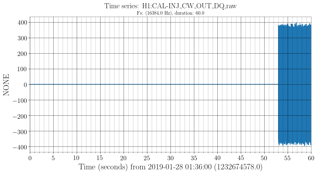
The CW hardware injections crashed at Jan 27 19:50:13 UTC (around the time of the other crashes reported previously). I restarted them at Jan 28 01:36:53 UTC (see screenshot).
Sheila, Dave:
The h1oaf1 machine restarted itself at 11:48PST, which in turn caused a corner station Dolphin crash. I have capture the logs and am in the process of restarting all the models. Unfortunately since h1oaf1 rebooted itself, its logs at the point of the restart have been lost.
The attached overview shows that h1oaf1's models are the only ones on the corner station dolphin'ed machines which do not have major errors.
The good news is that this is not a spontaneous Dolphin crash which is hopefully fixed by the Dolphin EEPROM upgrade on the 8th, unfortunately this resets the no-crashes-since-eeprom-upgrade timer after 19 days of running.
Opened FRS12217
Reminder that h1oaf1 is unique in that it is the only H1 front end computer which has no attached IO Chassis. Its IOP is a virtual-IOP, getting its timing from h1ioplsc0 (time master) via the Dolphin network.
All models back up and running. Although it may not have been necessary, I restarted h1oaf1's models (following h1lsc0) to ensure everything was started cleanly.
Handing over to Sheila for IFO recovery.
Thomas Vo, Sheila
These are the steps we are taking to recover.
We were locked at 2W and investigating ASC problems unrelated to the computer crash about 6 hours after the crash.
Danny, Kara, TVo
Danny had come in today and the ISC_LOCK guardian was in error mode (red box) at OFFLOAD_DRMI_ASC. This was mostly due to implementing a lscparams.asc_gains dictionary in ISC_LOCK, nothing major in the logic just a few typos and ISC_LOCK was calling the parameters this way: lscparams.asc_gains.key1.key2.key3 but we changed it to scparams.asc_gains[ 'key1' ][ 'key2' ][ 'key3' ]. This was true for a few other loop engagements so we changed those as well to be consistent.
Then we tried to go up to Nominal Low Noise but was still plagued by some DHARD instabilities at approximately 4 Hz, this continued even when playing with the gains a bit to stay away from the instabilities mentioned in Jenne's aLOG. This is particularly hard wrangle with because there's a lot of zero crossings...
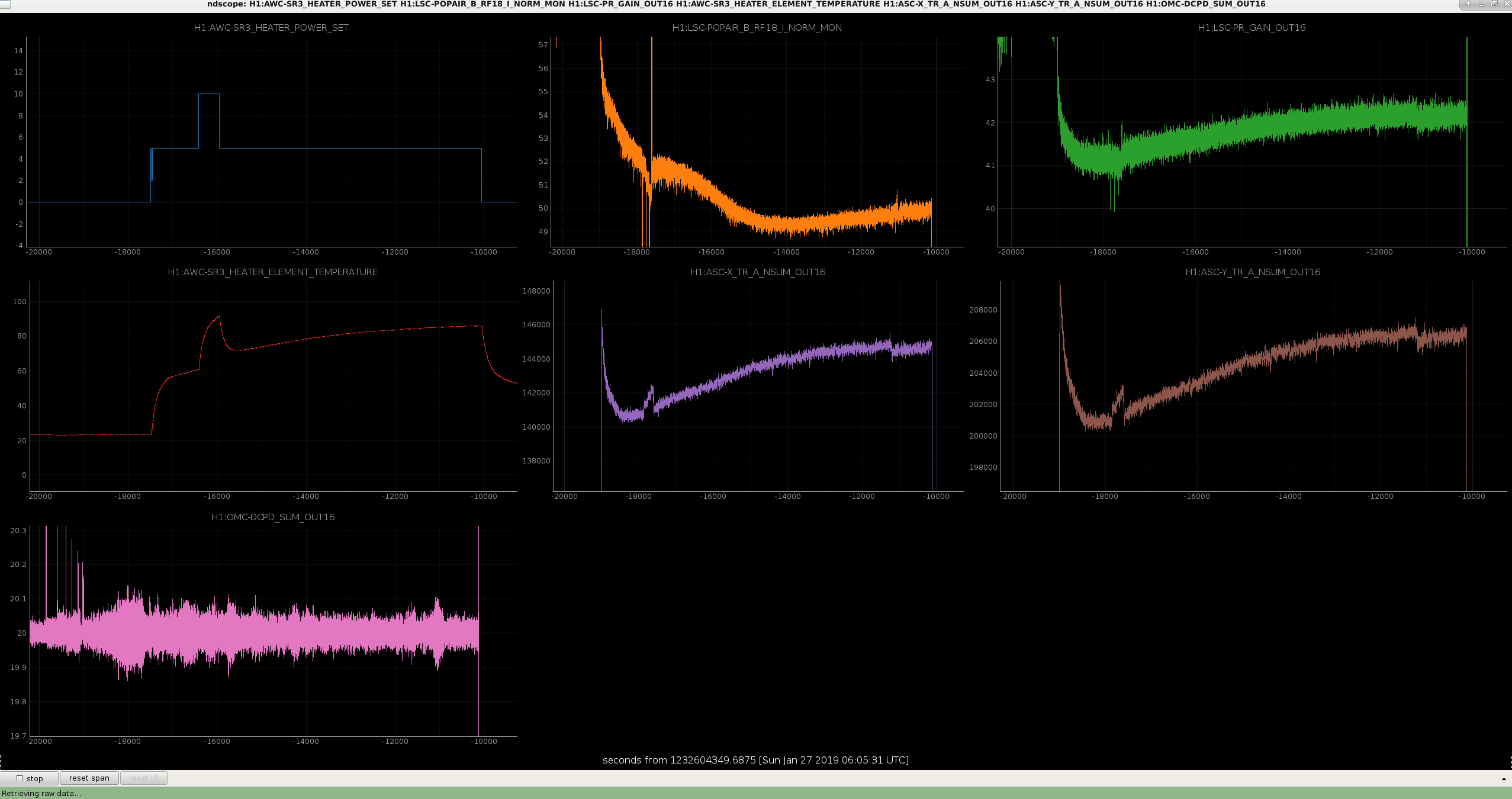
So we decided to try to test the SR3 heater to see if it changes any of the interferometer build-ups, but because we couldn't get to low noise we weren't able to test what happens to the DARM cavity pole. We tried to see if the coherence between the 9 MHz HOM mode and the OMC_Trans would also change but without going to a low-noise configuration, the coherence between OMC_A_NSUM and OMC_DCPD_SUM was unsurprisingly dominated by other noise. Attached is a trend of some of the buildups after getting to 30 watts and turning up the SR3 heater. There isn't much going on in the way of improvement except for a slight bump in POP18 at -15000 seconds. We stayed lock with all ASC loops closed at high bandwidth. As I write this aLOG, I think the 72Mhz signal would be the most sensitive to this so maybe we should have injected a line to SRM to measure the response...
We were stable for a few hours and then a timing error on H1IOPSEIH45 crashed the ISI and HEPI, so we phoned Dave and brought them back with a startWorld.sh reboot. However, the AS port camera looked very misaligned after coming back so we has to re-align quite a bit. Leaving it locked at 30 Watts in high bandwidth.
On 24th October 2018 I found some of the Beckhoff SDF systems were unresponsive (alog-44798), at that time I started an hourly script which checks that the display list responds to commands. I've been checking the SDF status periodically, more infrequently recently.
Today I found that h1ecatc1plc2sdf is reported as being unresponsive, which I verified by trying to change the channel list from 'differences' to 'not monitored' channels. I think Daniel was using this SDF on Tuesday, so presumably if has failed in the past 4 days.
I'll restart this faux-model on Monday, and change my checker to email problems if the time-between-failures is as large as 3 months.
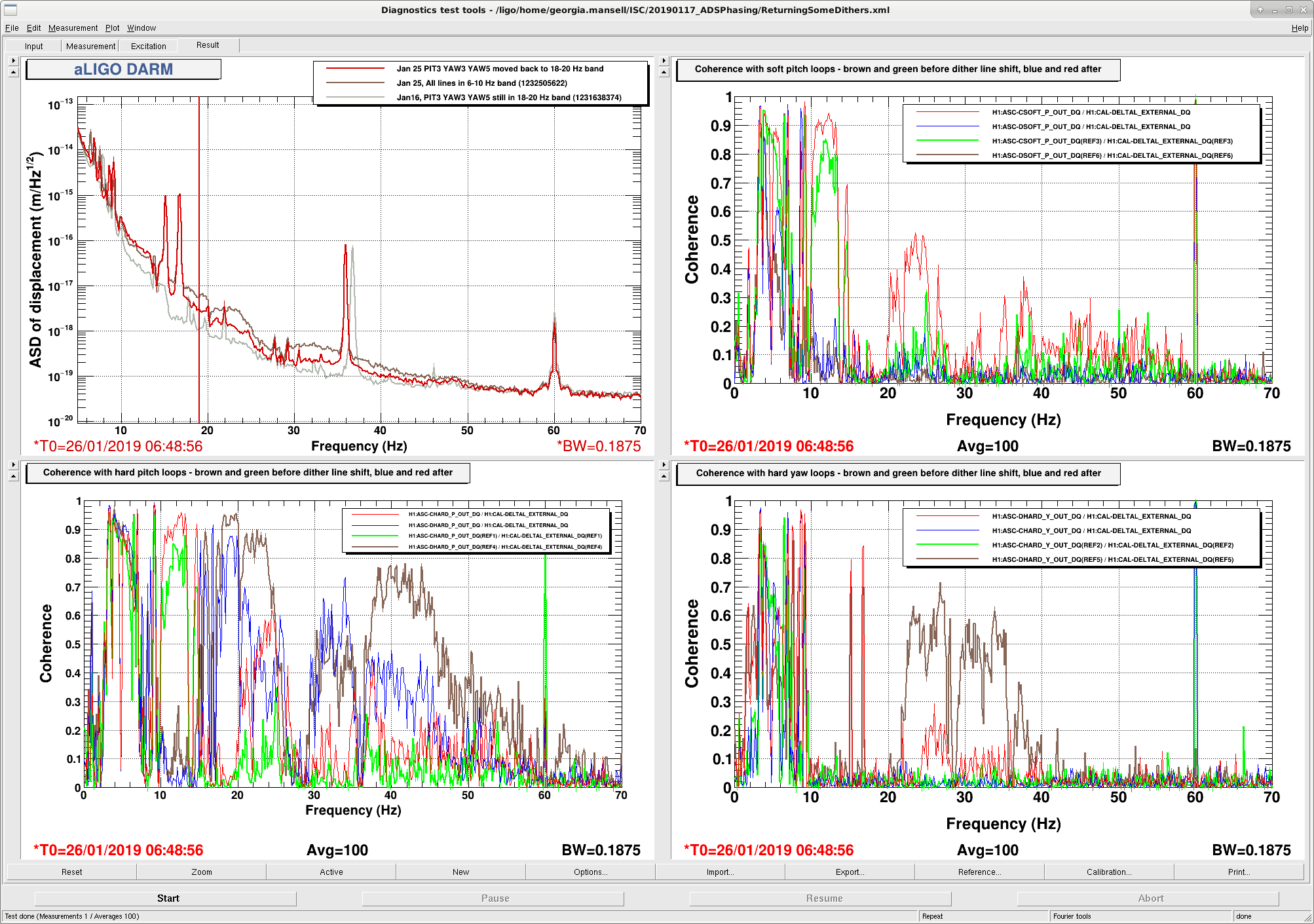
For most of the week we have had extra broadband noise in DARM, in the 10-50 Hz region, coherent with our ASC signals. The obvious difference between last week and this week is on Sunday I moved three of the alignment dither lines to low frequency. Today Sheila and I moved those lines (PIT3 YAW3 and YAW5) back to their 20 Hz frequencies. This reduced, but did not eliminate, the extra noise in DARM and the coherence with the hard loops.
In the attached spectra the top left is DARM, brown is early this evening with the dithers all in the 6-10 Hz band and red is after returning PIT3, YAW3 and YAW5 back to the 18-20Hz band. Grey is a reference from Jan16, when the dither loops were in the same configuration as the red trace, but the noise was lower. The other plots show coherence with the ASC loops (Hard pitch and yaw on the bottom left and right, soft on top right [we are not using the soft yaw loops at the moment]). Brown and green references are from today when all the dithers were in the 6-10Hz band; red and blue are from after the three dithers were moved back to the 18-20 Hz band, and the loops allowed to re-converge. The hard loop coherence with darm was reduced, most noticably in the 35-60Hz region for DHARD P, and 25-40Hz refion for DHARD Y. The soft loop coherence got worse with the new dithers.
We're not sure why the A2L decoupling is worse with the lower frequency dithers. There is certainly cross-coupling between the loops.
I've reverted to the 18-20Hz dither lines for PIT3 YAW3 and YAW5 in the guardian, but weekend commissioners may have to proceed through ENGAGE_SOFT_LOOPS (and CHARD_BLEND and LOWNOISE_ASC) with caution. I've left the gains pretty low so it might take too long for things to converge. I tried testing out lock requisition tonight but we've had an earthquake that has made things a bit tricky.
Another warning to tomorrow's commissioners tonight in ENGAGE_SOFT_LOOKS CSOFT P, the dithers, INP1 and SCR1 all rang up at once and unclear if the cause was the earthquake, or something else. We later had a lockloss in CHARD_BLEND that looked like chard pitch was responsible...
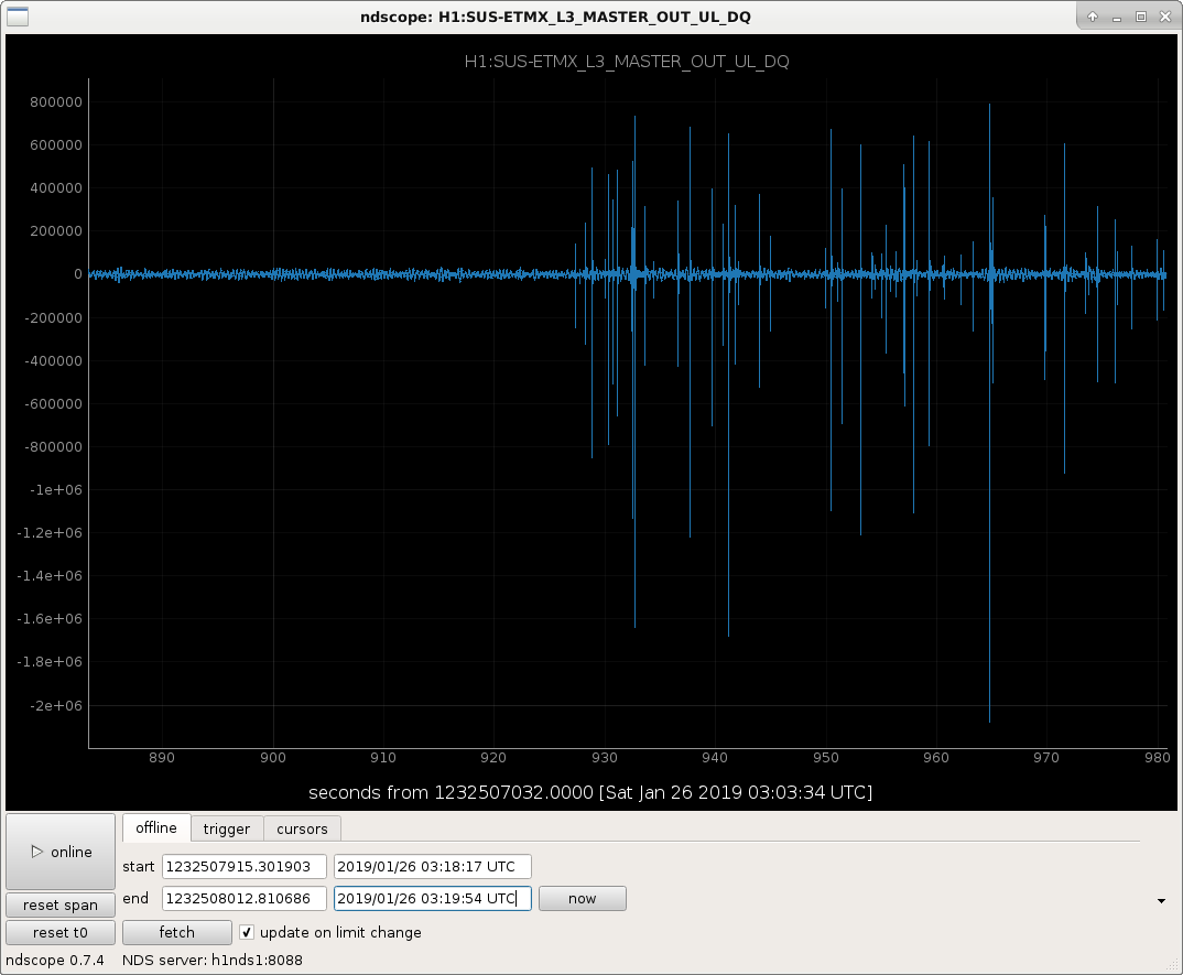
Another thing to note during this evening's lock: We had period of continuous glitching of EX ESD, maybe a bad glitch caused other glitches? EX L3 saturated for a few minutes with many glitches from 03:15:57 - 03:24:12 UTC (Jan 26). Second attachment is a screenshot of the time seri
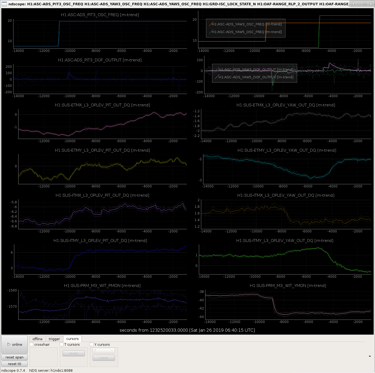
Keita suggested I look at the op lev trends while we were shifting the dither line frequencies, to see how much the test mass pointing changed over the course of the lock. First attachment shows dither frequencies, and outputs of the dither loops, test mass op-levs, and PRM witness sensor. When turning PIT3 and YAW3 on at the new dither frequency, ITMY pointing changes by ~1 urad, and PRM changes by a few counts. When YAW5 convergest with the new dither frequency, ITMY and ETMY have both moved by roughly 1urad.
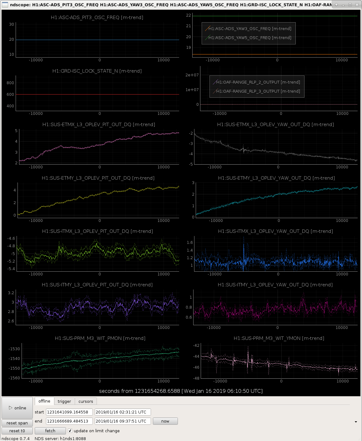
I was initially concerned by this shift in pointing, but I had a look at the op levs over the course of a long lock earlier this month and it seems that we see much larger excursions over the course of a normal lock (second attachment).
This alog only includes settings that worked and quick transfer functions. Still working on the noise budget
Here's the original scheme we are using now https://dcc.ligo.org/DocDB/0150/E1800057/002/E1800057-v2.pdf
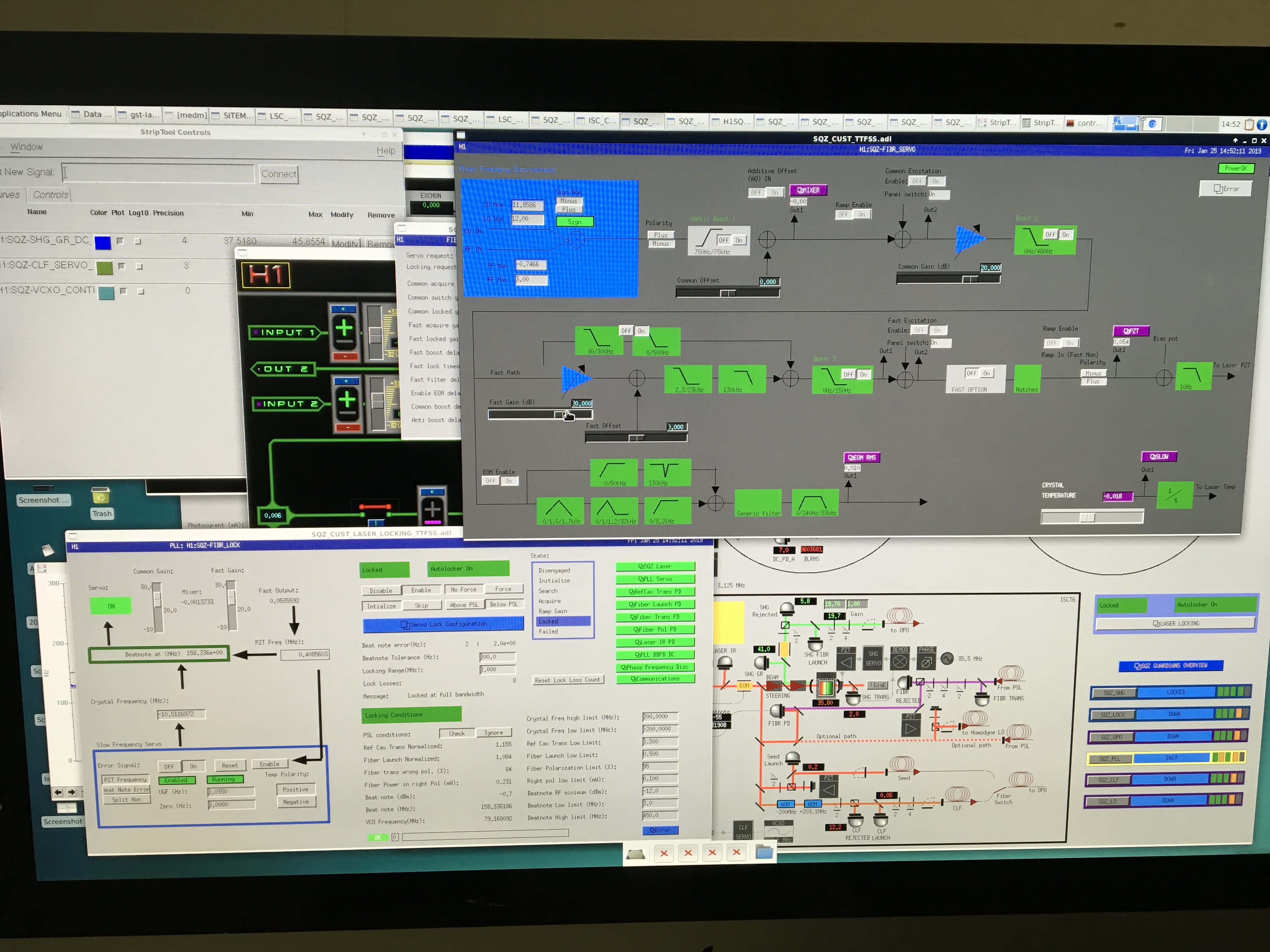
TTFSS
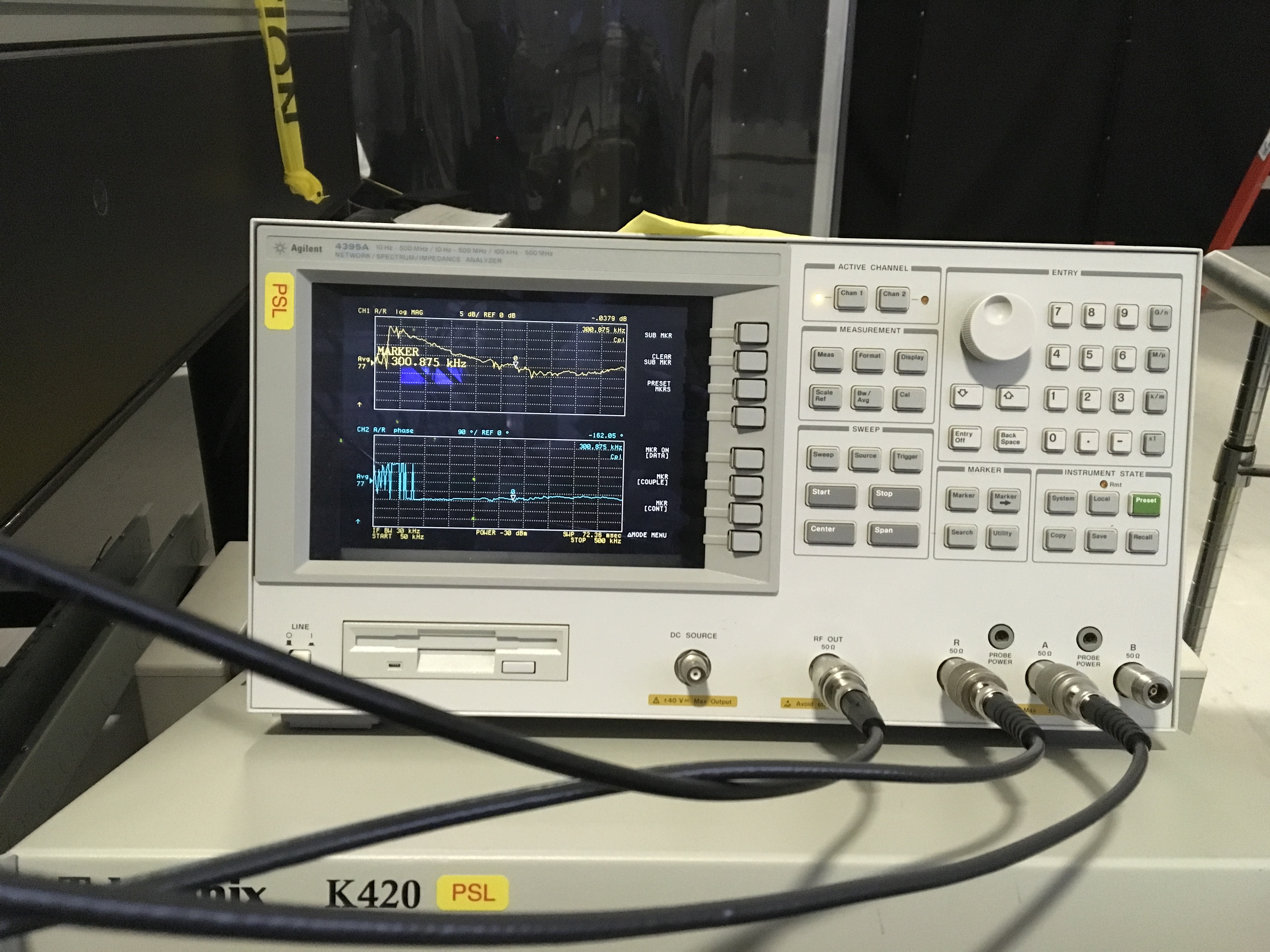
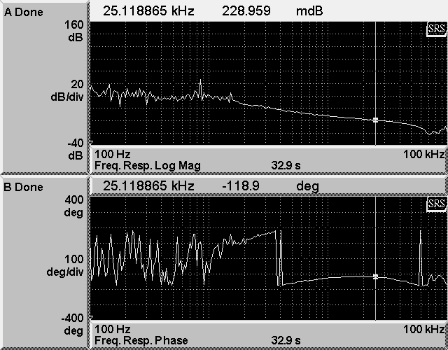
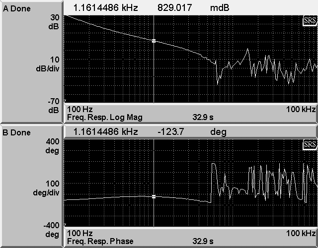
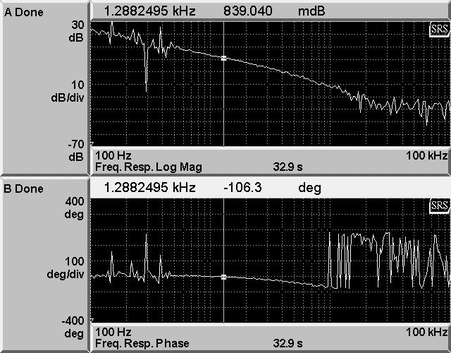
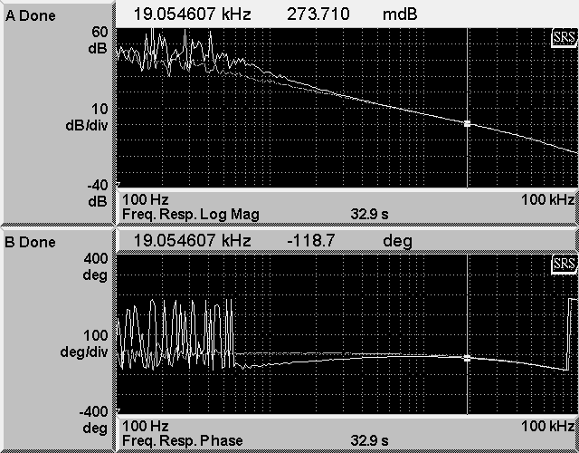
After we found the HV was off this morning everything else worked fine. Daniel got the Beckhoff auto locking to work again. The UGF can be pushed to 250kHz until it started to run into some weird notches and bumps. From the RF transfer function it almost seems like there's a zero at ~~500kHz. We are back to using a PFD TTFSS for this scheme (S1700331).


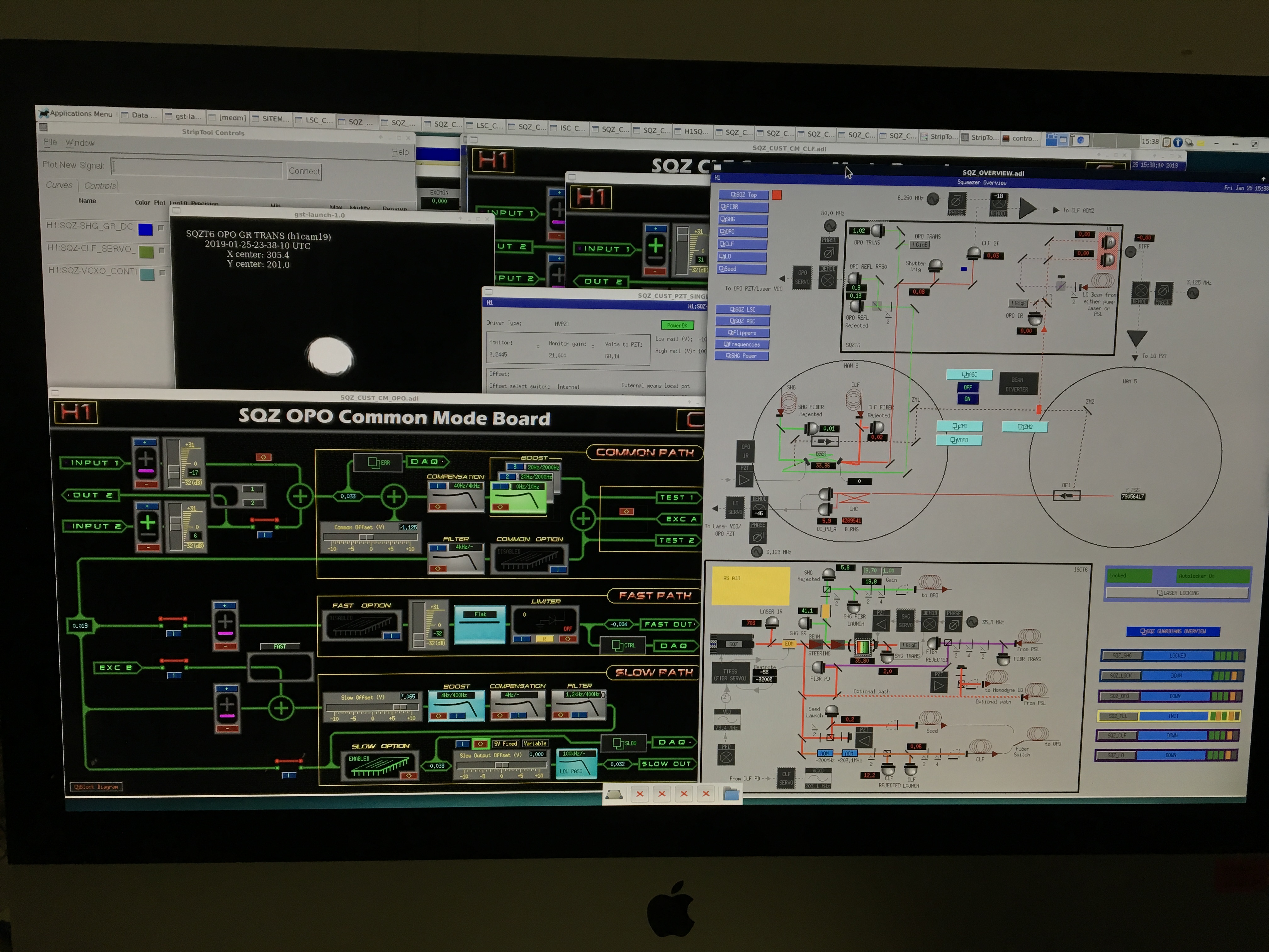
OPO
The UGF can't be pushed much beyond 1kHz as it would ring up 15kHz line and harmonics. Which means we can't engage 20/2000Hz boost. 6kHz notch (slow option) is used. 80MHz LO and OPO refl RF signal is now sent to OPO common mode board. The slow output goes to PZT driver (CH3 I think). PDH Vpp is 222mV at 0.5mW input to the OPO.


CLF
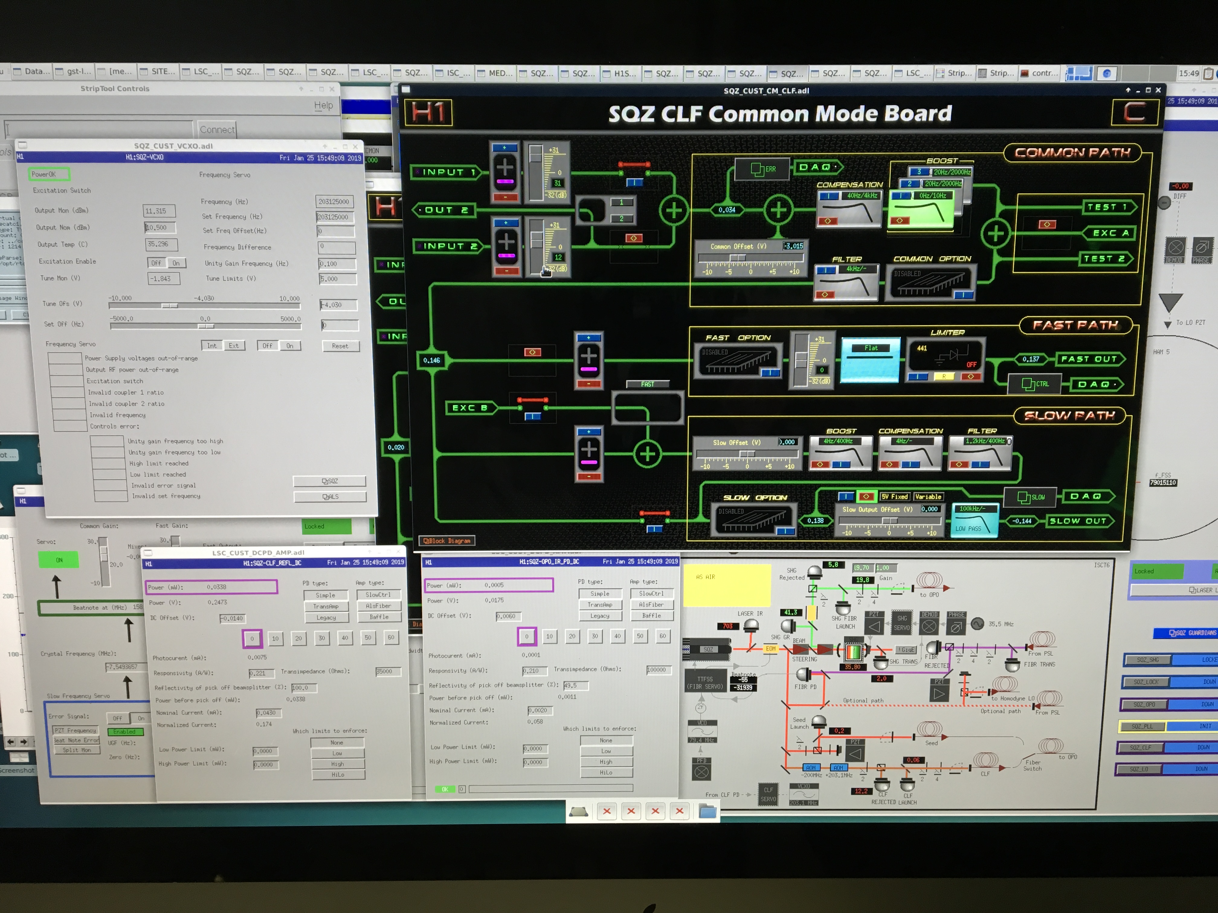
Nothing changed here. I just wanted to include the setting. I only pushed UGF to ~1kHz since low power CLF is mostly limited by sensing noise beyond 1kHz. The best CLF power to operate with OMC is to be determined (another overdue alog).


LO
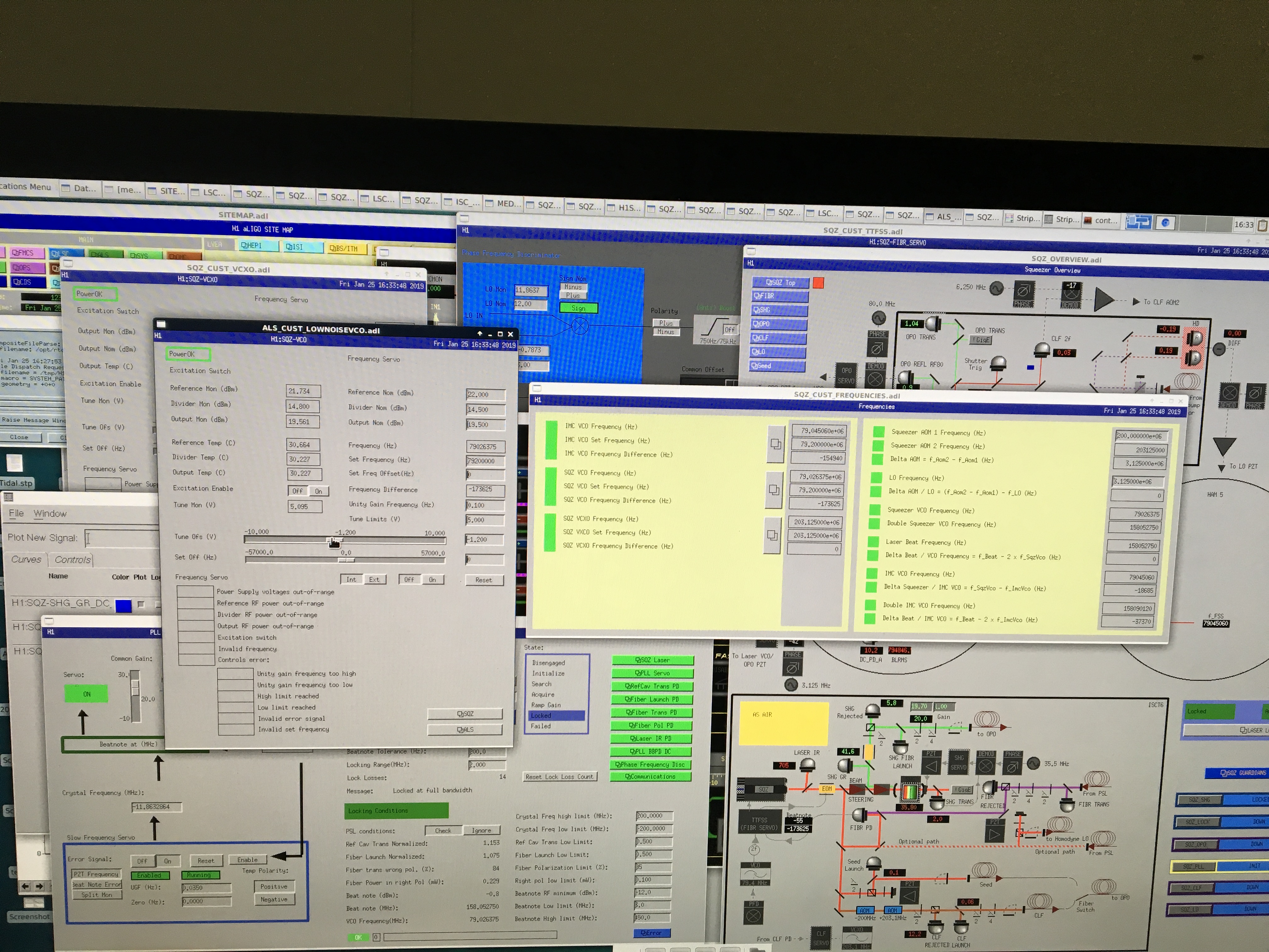
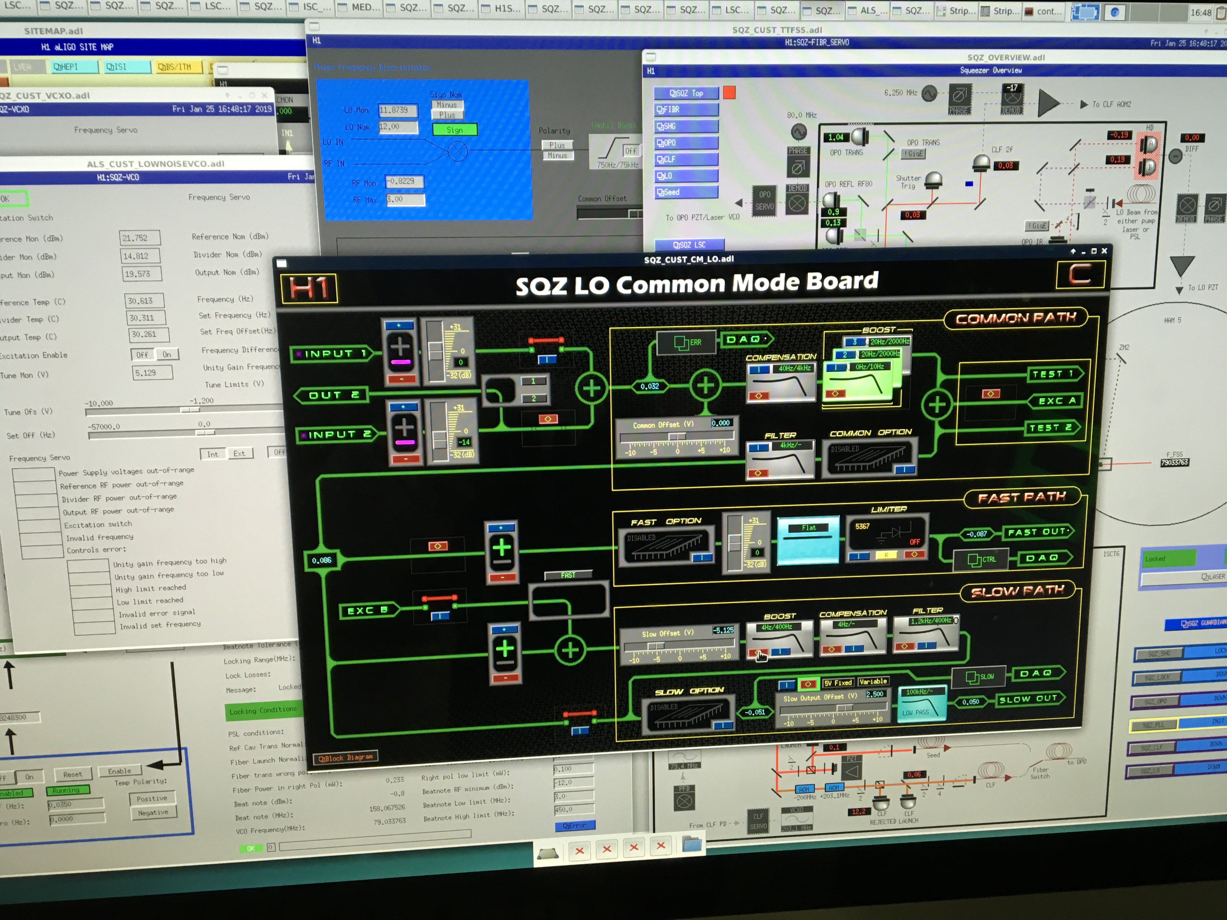
Fast output of LO common mode board now goes to the 79.2MHz VCO (that eventually hooked up to the frequency doubler). Now that both OPO and laser PZTs are in-loop in order to adjust the laser frequency so that beat note freq - (2 x IMC VCO freq) = 0 (for 3 MHz locking) the only knob I found work was to adjust the VCO offset itself.


We had a few avoidable ASC problems lately, which might have been easier to avoid if the way our ASC was in the guardian was a bit more clear. Today we had a couple of locklosses because of a CHARD Y gain setting (in the CHRAD blend state) that must have been intended to be used in combination with the +30dB filter, which is now turned off. It looks like the gains were updated in some guardian states but not others. We had a similar problem last week where we were turning on DSOFT Y accidentally because we didn't realize it was set in multiple places in the guardian.
We also had at least one, maybe two, locklosses that were caused by a guardian same state redirect in offload _DRMI_ASC, where the mich asc gain is saved in a variable, set to zero, then reset to the variable latter (same state redirect means it is set to zero and stays zero). Thanks to TJ for figuring out why that happened.
In an attempt to help us avoid thees situations in the future, and get a more clear idea of what is going on, we started to move our ASC gain settings into LSC params. Having all the gain changes collected in one place it becomes clear that we are doing gain changes which are probably unnecessary. For now we have only moved the settings for CHARD, DHARD, and MICH into LSC params, but I will plan to finish this at a later time.
We also found and fixed some things that were written in an unnecessarily confusing way, for example we have some if statements where the same settings are set in either case. We tried to move these things out of if statements. We also have settings for hard loops inside if statements about using the soft loops, which might actually need to be different but might not (we have left them in).
We have been trying to move things into guardian states where the name of the state is descriptive of what is happening (ie, so that we only have soft loop things happening in ENGAGE_SOFT_LOOPs, or so that all ASC changes happen in states that are ASC related). For this reason we moved the changes in gain for the CHARD loops from engage soft loops into ENGAGE_FULL_IFO_ASC, so these gain increases are now happening sooner than they were. (Previously we went through three CHARD gain settings in the course of these two guardian states, we have reduced that to only two settings now, it probably could be just one since we are using smooth limiters).
Apologies that this caused difficulty yesterday.
Today I continued in the same theme to move the radiation pressure compensation settings, which were hard coded in three different place (INCREASE_POWER, ADJUST_POWER and POWER 30W) into parameters, and I moved the adjustment into a function in ISC_library.
Also moved the soft loop settings into the parameters file.
TITLE: 01/25 Day Shift: 16:00-00:00 UTC (08:00-16:00 PST), all times posted in UTC
STATE of H1: Commissioning
INCOMING OPERATOR: None
SHIFT SUMMARY: A few low noise locks before commissioners would knock us out. Commissioning continues.
LOG:
1736 Kyle to MY
1802 Nutsinee to ISCT
1950 Nutsinee out
1955 Kyle back
2030 Jim trying out new blends on HAM4 & 5 (reverted after testing)
2121 Nutsinee to ISCT6
2130 TVo and Danny to EY
2208 TVo to EX, then back to EY to pick up Danny
2243 TVO and Danny back
SudarshanK (remotely), Dimitri Estevez (Virgo), and RickS
On Tuesday of this week, we installed the new Pcal PD-to-integrating-sphere adapters for the Tx and Rx sensors at Xend and calibrated using the upgraded Working Standard, WSH.
Results of that calibration work will be appended to this entry.
Today, we converted to calculating the force coefficients for the Tx and Rx PD readback channels in the Front End code.
This involved updating epics values and switching of filters as was done earlier for the Yend (see Link).
The new epics record values are in the attached text file and in the SVN at
/ligo/svncommon/CalSVN/aligocalibration/trunk/Runs/O3/H1/Results/CALCS_FE/lho_end_pcal_epics_created-20190125.txt
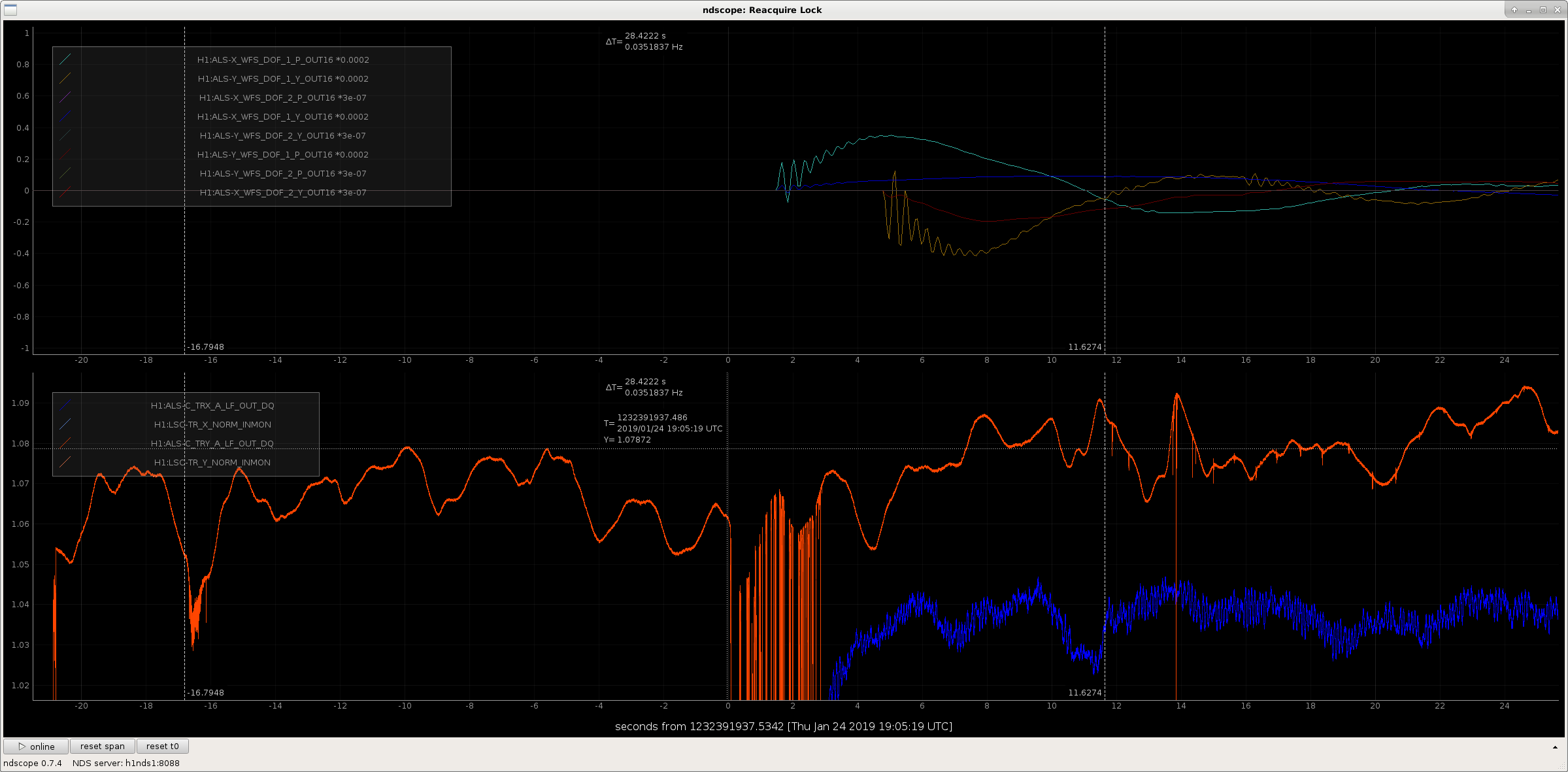
J. Kissel, reporting for F. Clara, R. McCarthy (Tappers), J. Driggers, S. Dwyer T. Shaffer (Witnesses), K. Kawabe (Photographer) After pictured recently by Keita (LHO:46607), Richard and Fil drive down to similar spots along the exposed Y-arm communication fiber bundle -- which includes the PSL to ALS laser optical fiber connection -- and tapped on it while we happened to be locked on ALS. The attached screenshot shows a time series of (among other things) the Y ARM power transmission in green laser power [Brightest Orange Trace], usually the canary in the coal mine when we're having "ALS glitches" and "it's raining." A T=16 sec are the beginnings of taps. At T=0 sec are the most invasive taps. At T=+11 sec there is more tapping. The times are all around 2019/01/24 19:05 UTC. These taps, and corresponding response of the Y arm transmitted power are representative of the range of impact that we've seen that impacts locking of ALS, which has cost us many an evening of frustration. This is likely the source of *some* (if not all) problems with ALS glitches, and was associated with rain (presumably the wind / rain would cause the same level of tapping Richard and Fil were inducing). This issue is related to the following FRS Tickets: FRS:11113, FRS:12209 Previous reports of ALS Y vs. Rain: LHO:46554, LHO:46302, LHO:45924, LHO:45891
Just looking at the time series that Jeff plots, these don't look convincingly similar to the glitches which we have when no-one is tapping the fiber.
For some examples, see plots attached to 17576 22184 25523 36602 laser safety tag problem: 36645
Kara Merfeild is working on some code to try to look for corelation between glitches and weather.
Another step that we could take is to make a script or some other easy way to do the test where we lock the green laser to the arm bypassing the PLL (making sure that we have a reasonable loop), so that next time we have a rainy day we can easily switch the configuration to test if the glitches go away when the fiber is not involved. Setting this up would be a good Tuesday morning activity.
Koji, Georgia, Craig
This evening we ran several tests of the electronics handling the CARM signal around the PSL racks.
----------------------------------------------
Analog to Digital REFL Calibrations
----------------------------------------------
We looked at a bunch of peak values while injecting a 9.101 MHz sine wave into the demod boards.
Our biggest confusion was probably the factor of 500 response difference of the REFL A and B 9 demod boards to the same input signal.
We unplugged and terminated the signal coming from the photodiodes, and set the Agilent to give a 9.101 MHz, -20 dBm signal into RF In on each demod board. Then we read out the signal seen on REFL {A,B} {I,Q} MON demod board analog outputs, as well as the digital channels. Peaks read out with flattop windows power spectra, not PSDs.
Channel Response
----------------------------------------------
H1:LSC-REFL_SERVO_ERR_OUT_DQ 1.59e-3 cts
H1:LSC-REFL_A_RF9_I_ERR 4.38e-1 cts
REFL A 9 I analog monitor 346.7 μVrms
Moved injection to REFL B RF In:
H1:LSC-REFL_B_RF9_I_ERR 1.17e-1 cts
REFL B 9 I analog monitor 120.0 mVrms
Moved injection to REFL A RF In again:
REFL A 9 I analog monitor 340.3 μVrms
REFL A 9 Q analog monitor 342.1 μVrms
Moved injection to REFL B RF In again:
REFL A 9 I analog monitor 120 mVrms
REFL A 9 Q analog monitor 120 mVrms
Demod boards are DCC D1000181, Serial numbers are S1000772 for REFL A, S1000771 for REFL B.
We also note the frequency response ratio of CARM OUT2/REFL A 9 I analog monitor = 13.1 dB, while the Sum Node A Input 2 gain = 8 dB and CMB IN1 gain = 6 dB. Not bad.
----------------------------------------------
CARM Circuit Voltage Noise
----------------------------------------------
Basic CARM Path
9 MHz Beatnote ---------> REFL A PD ---------> REFL A 9 Demod Board ---------> Sum Node ---------> Common Mode Board (CMB) ---------> IMC Board ---------> IMC VCO
We measured the intrinsic electronics noise of the REFL A demod board, Sum Node, and first part of the Common Mode Board. Sum Node A Input 2 gain = 8 dB, CMB IN1 gain = 6 dB. We preamplied the circuit signal by 100 with an SR560 to avoid the SR785 noise floor. We took four sets of spectra:
1) Demod RF In 50 Ω terminated, CMB OUT2 measured
2) Sum Node A Input2 50 Ω terminated, CMB OUT2 measured
3) CMB Input1 50 Ω terminated, CMB OUT2 measured
4) Demod RF In 50 Ω terminated, REFL A 9 I analog monitor measured
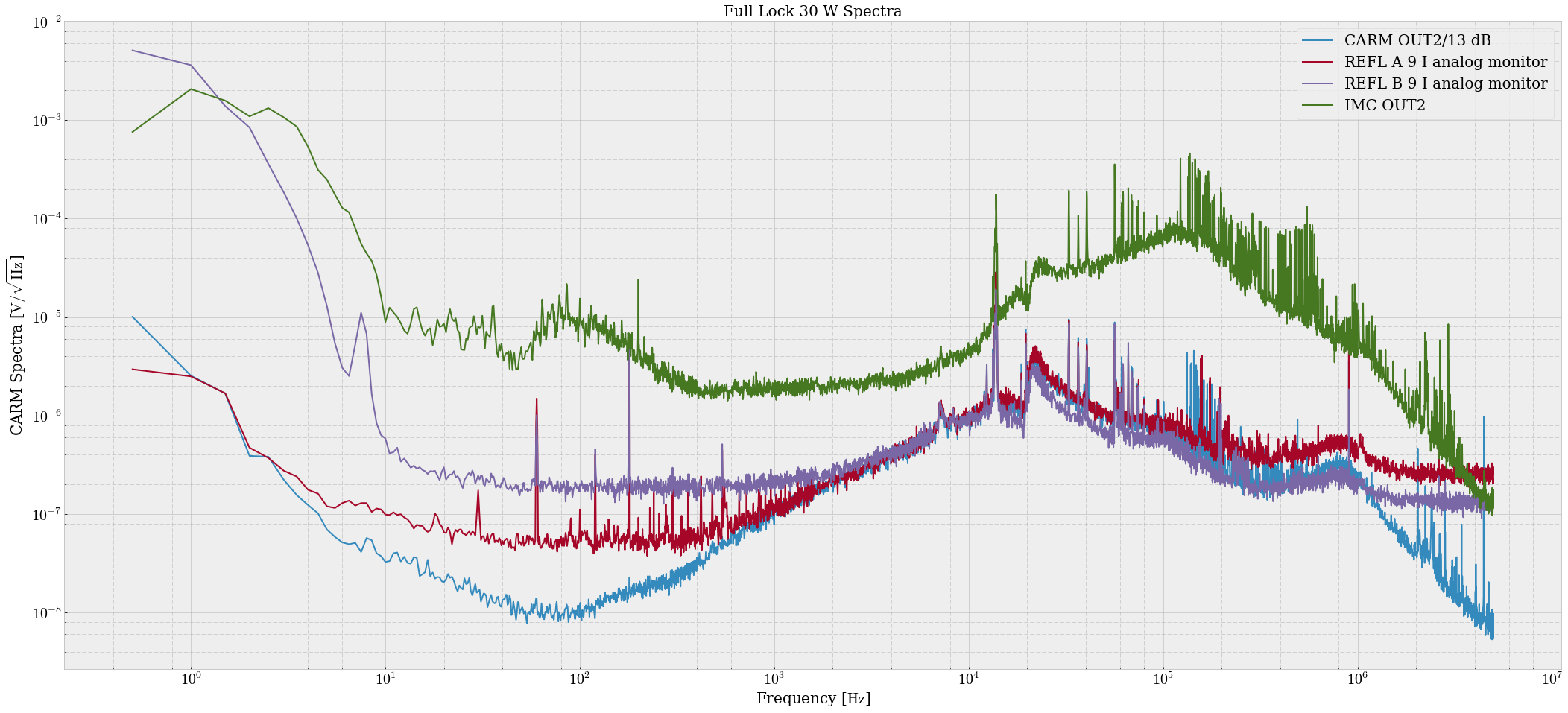
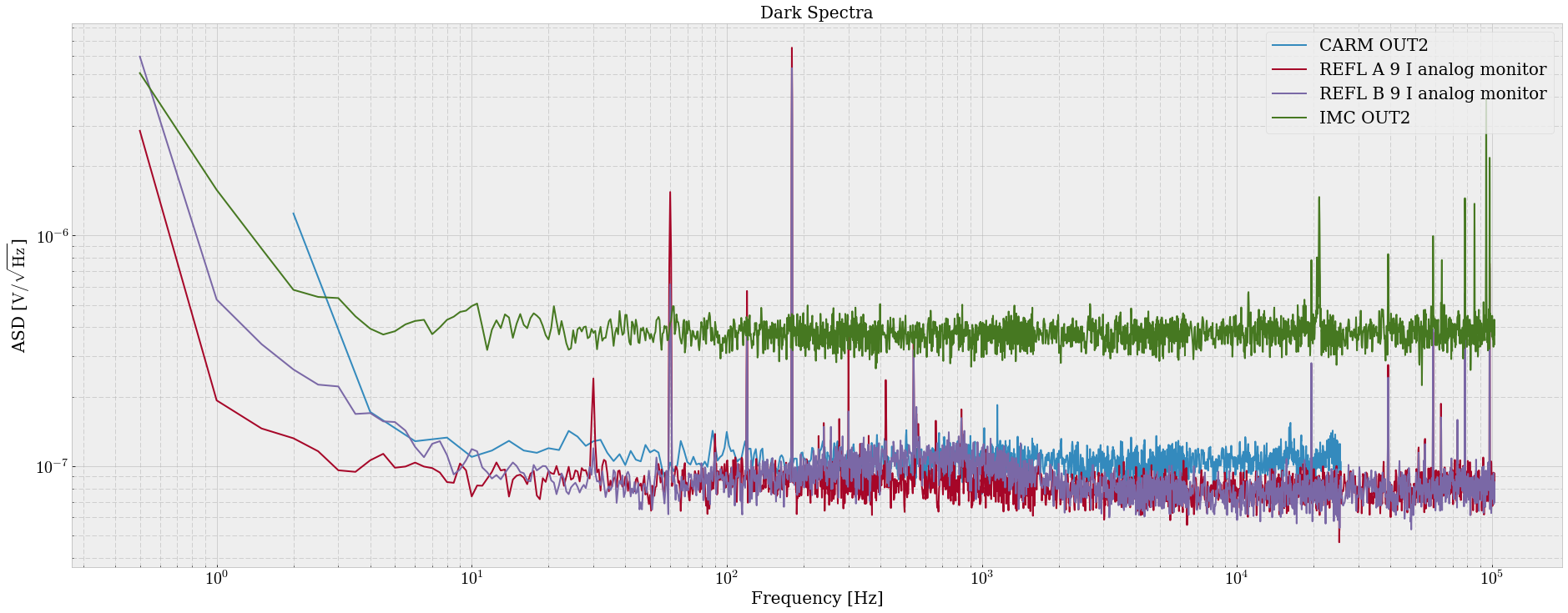
The (scaled to remove the SR560 gain) results of these measurements are shown in attachment one. It appears that the worst circuit noise originates in the Sum Node.
The big hump in the dark orange spectrum is probably a random RF line wandering through DC during our measurement, it is not present in the other measurements at low frequency.
During these measurements with OUT2, we noticed an mysterious peak wandering around at 60-80 kHz. Georgia was able to toggle the frequency of the line with the Sum Node B Input1 being turned on and off, even though IN2 on the CMB was NOT connected.
----------------------------------------------
What does any of this mean for the CARM path? The question came up when I measured REFL A 9 IMON and CARM OUT2 paths, and found that CARM OUT2 had lower noise than REFL A 9 IMON would have predicted. (red and blue in attachment two)
All it likely means is there is some additional sensing noise in the CARM path that we are just now understanding.
Also somehow the responses of REFL A and B analog monitors are vastly different to the same input.
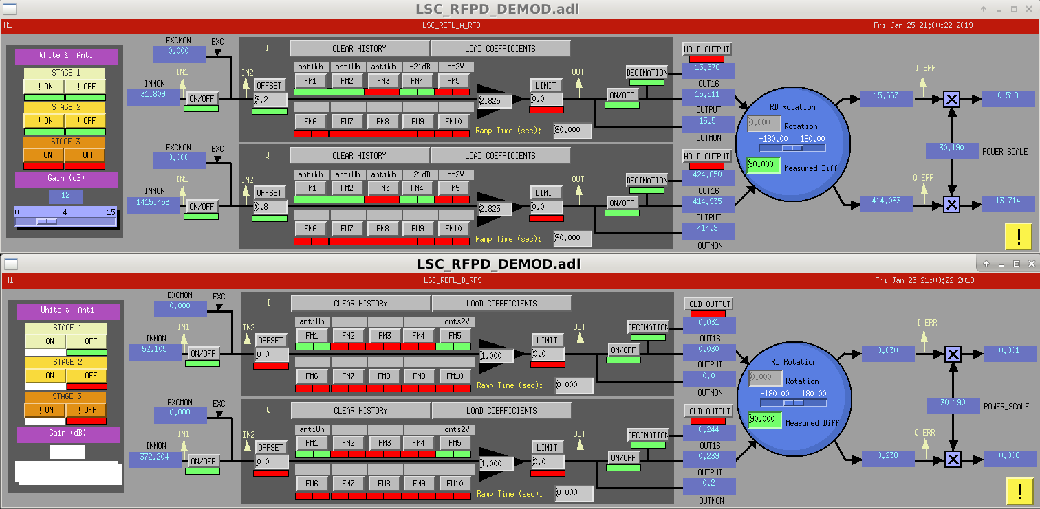
After some conversation with Daniel and more thinking, things seem bad for the REFL A demod board signal. We put in -20 dBm (22.4 mV) into RF In, and got back 346.7 μV from REFL A 9 I and Q, and 120 mV from REFL B I and Q. Barring some measurement mistake, the signal gain for the REFL A demod board is 0.0155. For the REFL B demod board it is 5.36, much closer to spec. The analog response ratio REFL B / REFL A ≈ 350. This is strictly a signal attenuation, the dark and shot noise of the signal chain is the same for both PDs. The LO monitors report the same input for both boxes. Same for the RF monitors. The digital readbacks of H1:LSC-REFL_A_RF9_I_ERR and H1:LSC-REFL_B_RF9_I_ERR are also consistent with low REFL A signal response. I reported 0.438 counts peak response in REFL A, and 0.117 counts for REFL B, but when looking at the calibrations we see that REFL A FM5 [ct2V] is not applied, while it is for REFL B. Assuming whitening is accounted for correctly, this is about a factor of 2^14/10 = 1638.4 cts/V difference, meaning the true REFL B / REFL A digital readback ratio is around 440. The demod circuit is relatively simple: DCC D0902745. If both analog and digital readbacks yield a low signal response the error in the board comes before the differential amplifier. We also see the reduced signal response in both I and Q channels for REFL A, indicating the error is probably before the PE4-140s. And if the RF and LO monitors report the same inputs for both boxes, the error is after the RF directional couplers. This means the most likely candidate for the signal attenuation is the transformers (TC4-1Ts), or somehow one of the directional couplers is not supplying what it claims to supply.
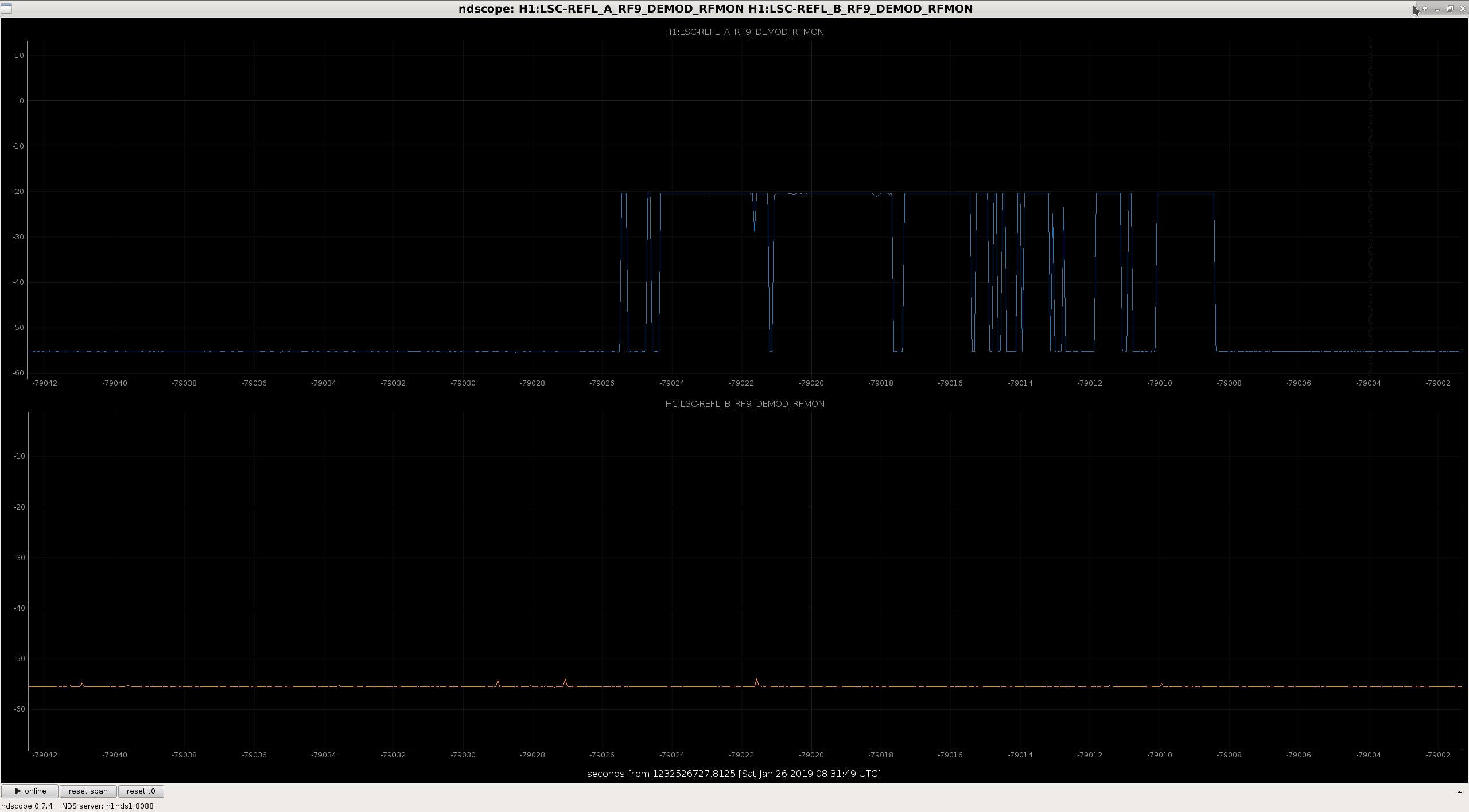
Went out there to repeat the demod board ratio measurement for REFL A because if any of the above were actually true, locking would be impossible, and our dark/shot noise measurements would have to be different between REFL A and B.
Turns out the Agilent RF source was not making a great connection when plugged into RF In. In attachment one, the blue RFMON shows the connection was spontaneously dropping while the measurement was happening. The cable must have been broken, since the measurement was repeatable.
This time I used a Marconi with 9.101 MHz and -20 dBm and exchanged the cable, and got a reasonable result:
Channel Response
-----------------------------------------------
REFL A 9 I analog monitor 117.6 mVrms
REFL A 9 Q analog monitor 118.2 mVrms
H1:LSC-REFL_A_RF9_I_ERR 48.4 cts
REFL B 9 I analog monitor 117.6 mVrms
REFL B 9 Q analog monitor 118.3 mVrms
H1:LSC-REFL_B_RF9_I_ERR 0.115 cts
The demod gain for both boards is 5.25.