Displaying reports 43461-43480 of 88617.Go to page Start 2170 2171 2172 2173 2174 2175 2176 2177 2178 End
Reports until 06:21, Saturday 19 January 2019
H1 ISC (ISC)
craig.cahillane@LIGO.ORG - posted 06:21, Saturday 19 January 2019 - last comment - 18:40, Sunday 20 January 2019(46541)
RIN Investigations
Koji, Craig

Koji has the idea that maybe our IMC FSR is not exactly equal to our RF 9 modulation frequency, and this is responsible for additional 9 MHz RF AM seen by Sheila and Jenne.
So today Koji and I moved the modulation frequency around.  We used the double modulation technique for finding the FSR by looking at the 24 + 9 = 33.178 MHz peak and trying to minimize it.  
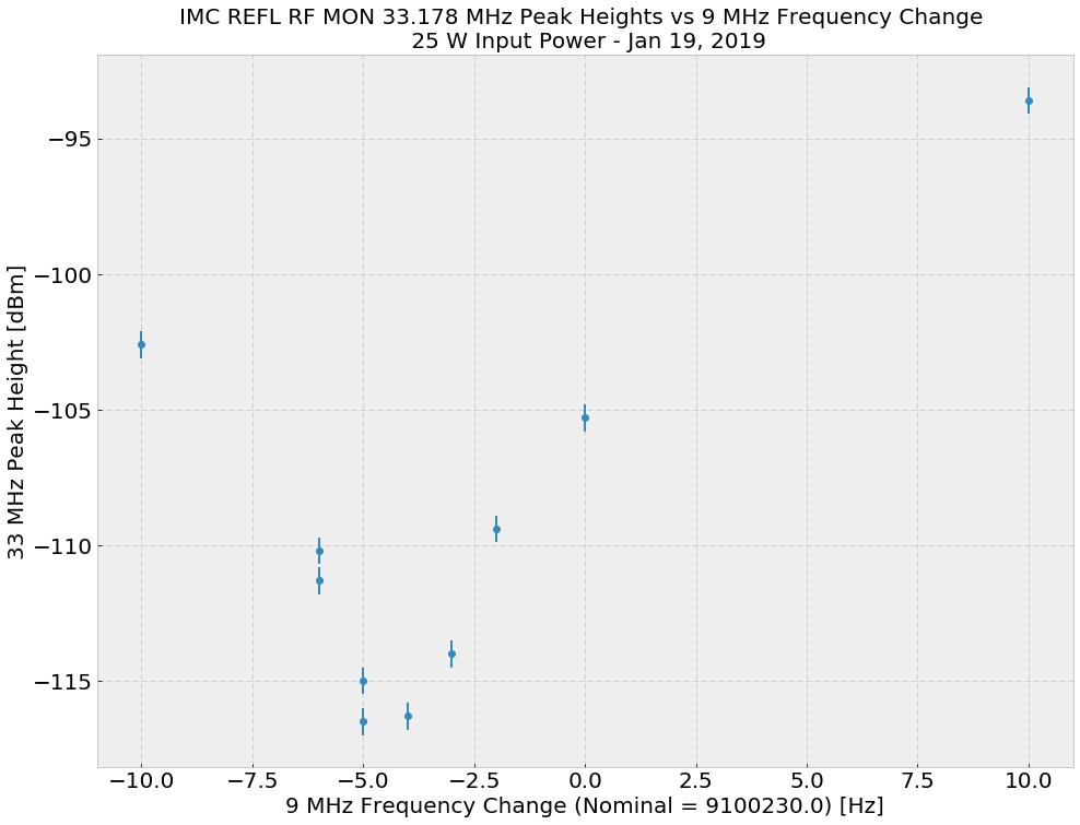
We found that the frequency was already pretty well tuned.  We moved it around from 9.100230 MHz and found the best rejection of 33.178 MHz peak at 9.100225 MHz.  Larger movement of the modulation frequency (on the order of 10s of Hz) resulted in much higher 33.178 MHz peaks.

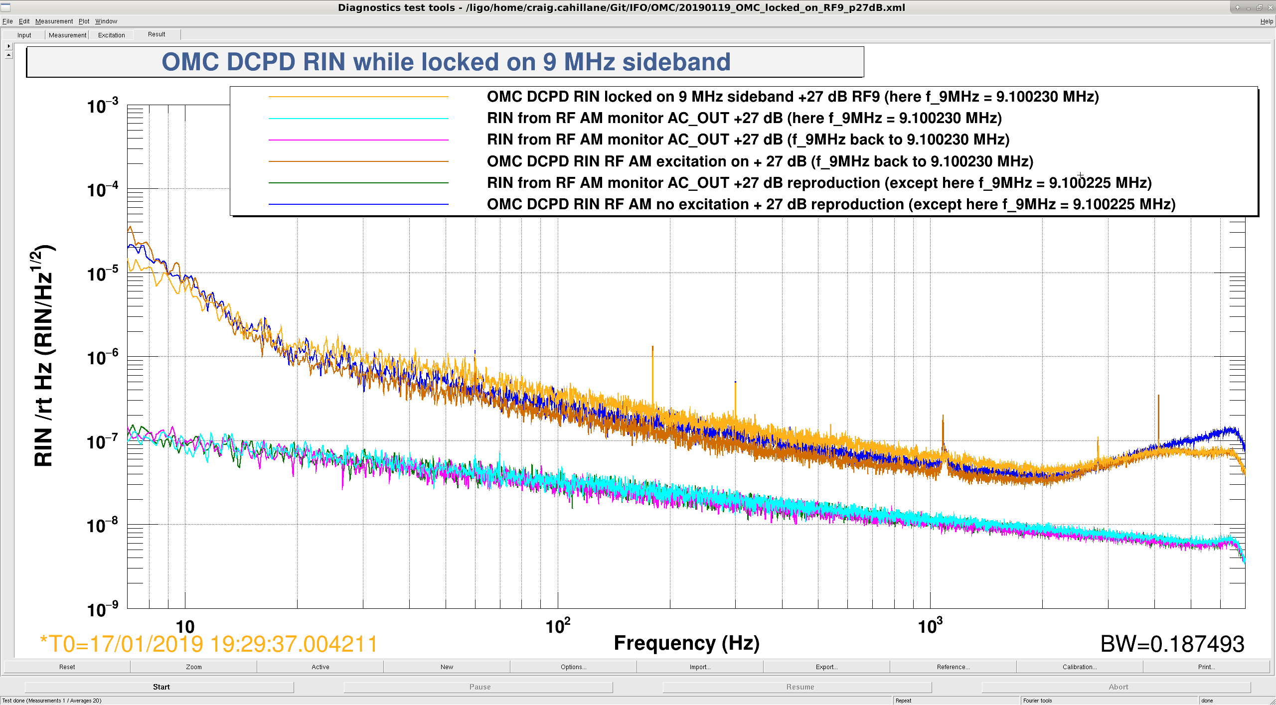
Then we tried repeating Sheila and Jenne's OMC 9 MHz locking test.  The results are plotted below.
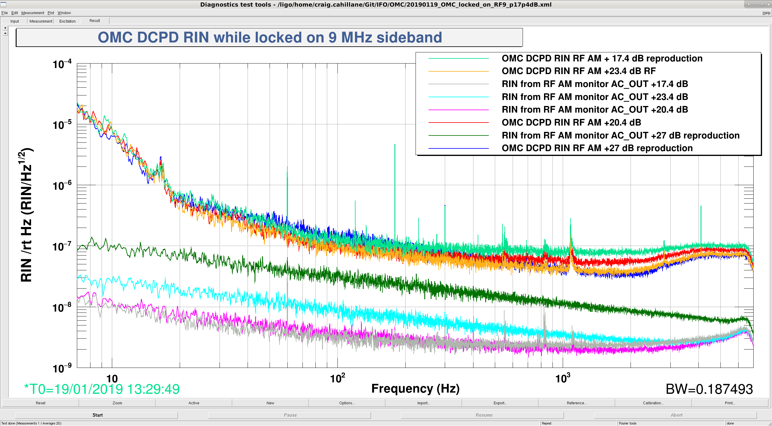
The first attachment shows the OMC DCPD spectra and RF AM monitor spectra, each one appropriately calibrated into RIN, for different RF9 modulation slider values.  We see a moderate (factor of 2) win from going from +27 dB to 23.4 dB, otherwise 9 MHz RIN remains about constant.
The second attachment shows the effect of changing the 9 MHz modulation frequency by 5 Hz.  The 9 MHz RIN seems to be independent of our frequency move. 

We note that the move from 23.4 dB to 27 dB on the RF9 slider actually does increase the modulation depth, since the OMC DCPD SUM increases when this is done.  Koji suspects that his measurements from before measuring the response of the EOM suffered from broadband saturations spoiling the linear response.  Going above 23.4 dB on the 9 slider is still not recommended.
We moved the modulation frequency back to 9.100230 MHz and left it there.

-------------------------------------------------------------------------

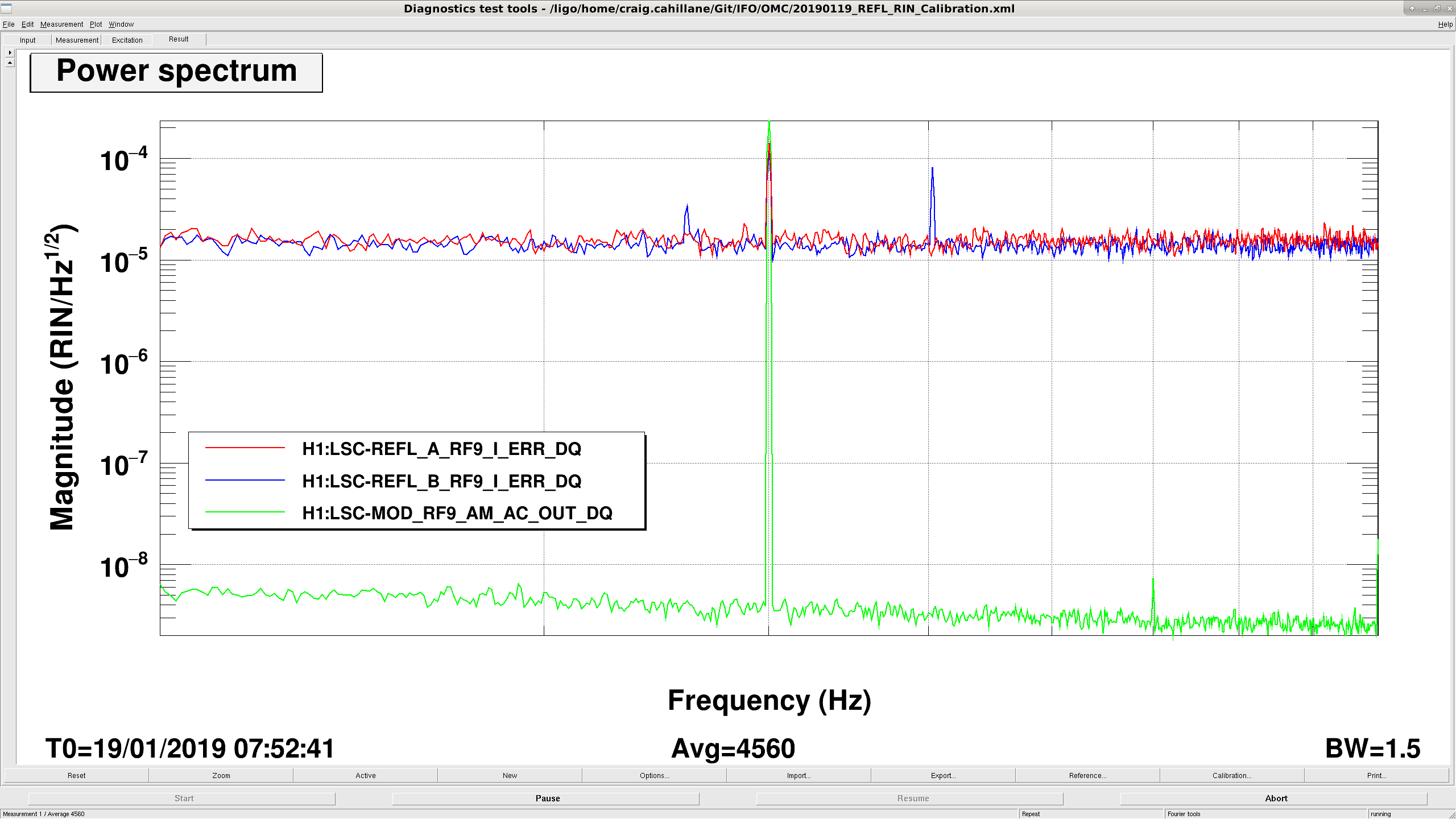
We also injected a line into the EOM driver for the 9 to calibrate the REFL A 9I pd into units of RIN.  It seems that REFL A 9I is a pretty poor RIN sensor relative to the OMC and RF AM monitor. (attachment 3)


Images attached to this report
Comments related to this report
daniel.sigg@LIGO.ORG - 10:09, Saturday 19 January 2019 (46544)

Optics Express 23 (2015) 19417; http://dx.doi.org/10.1364/OE.23.019417 and also alog 13378.

Back then, we measured 9.100235.6 Hz (paper) and 9.100229 Hz (alog). So the FSR changed by less than 11 Hz, or ~1 ppm. Or in other words, the cavity length of ~16.5 m changed by less than 20 µm, since the last measurements 5 years ago.

craig.cahillane@LIGO.ORG - 18:40, Sunday 20 January 2019 (46550)
Some notes about the measurement that were not mentioned before:

- We measured out of IMC REFL RF OUT with the IMC locked with 25 watts input requested.

- Attachment one is the data on the 33 MHz Peak vs 9 MHz changes we acquired.

- Attachment two is the calibration of REFL A/B 9I RIN we got by injecting AM into the 9 MHz stabilizer.
Images attached to this comment
H1 AWC (AWC, TCS)
daniel.vander-hyde@LIGO.ORG - posted 22:41, Friday 18 January 2019 (46540)
SR3 heating

TVo, Craig, Danny

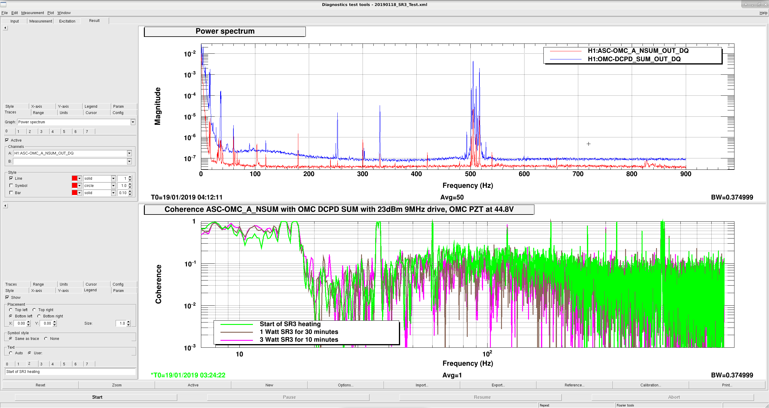
We'd hoped that by changing the SRC mode we could move away from co-resonating of higher order modes that could be propagating through the ifo (9MHz higher order modes from the OMC and the increased contrast due to mismatched absorption). 

What we looked at:

IFO configuration: 

Result: 

Modeling of the SRC is currently in the works to compare with our result. 

Images attached to this report
H1 ISC (ISC)
georgia.mansell@LIGO.ORG - posted 19:32, Friday 18 January 2019 (46539)
Some small ASC changes, BLRMS and OMC QPD coherence with darm offset

This evening we made some small tweaks to the ASC:

After we did the calibration sweeps, I tweaked the DARM offset slightly, looking at the DARM BLRMS and the coherence between the OMC QPD and the OMC DCPD sum (see attachment). I didn't see a change in the coherence between the QPD and the DCPD sum. During this test the 9MHz modulation was 20.4 dBm. I got excited about the change in the DARM BLRMS from 100-400Hz and 500-1000Hz (5 and 6 respectively) while changing DARM offset, seemingly finding a local minimum with a offset of ~16 (normally we operate at ~14.8). I'm not sure why there would be such a minimum. I've left the darm offset at 14.8.

Images attached to this report
H1 GRD (ISC)
yasmeen.asali@LIGO.ORG - posted 17:06, Friday 18 January 2019 (46536)
DRMI Lock Acquisition Analysis

Ana Lam, Madox McGrae-Menge, Yasmeen Asali, Emily Calamari

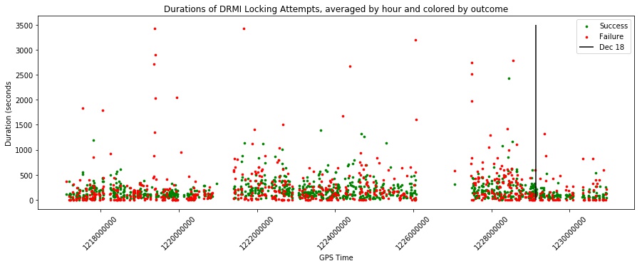
We worked on analyzing DRMI lock acquisition the past couple weeks with Sheila. We downloaded HI:GRD-ISC_LOCK_STATE_N data from August 2018 through January 2019 and examined the transition from Acquire DRMI 1f (101) to DRMI Locked Prep ASC (102) specifically calculating the duration and outcome of DRMI locking attempts. The scripts we developed can be found here.

The attached plot shows the past five months of DRMI locking attempt durations averaged by hour and colored by outcome, where "Success" indicates a successful transition from state 101 to 102 and "Failure" denotes any time the system reverted to a lower state. The vertical line marks December 18th when the TCS settings were reverted back to 30W, and we observed a statistically significant difference between the distribution duration means between the two time intervals (see github scripts for U-Test details).

Images attached to this report
H1 General
cheryl.vorvick@LIGO.ORG - posted 16:50, Friday 18 January 2019 (46538)
ops Day Summary

TITLE: 01/19 Day Shift: 16:00-00:00 UTC (08:00-16:00 PST), all times posted in UTC
STATE of H1: Commissioning

CURRENT ENVIRONMENT:
    Wind: 5mph Gusts, 4mph 5min avg
    Primary useism: 0.03 μm/s
    Secondary useism: 0.42 μm/s

INCOMING OPERATOR: None
SHIFT SUMMARY:  locking, in NLN
LOG:

H1 SEI
jim.warner@LIGO.ORG - posted 14:27, Friday 18 January 2019 (46531)
Monitor channels added to SEIPROC for OAF_SUSPOINT and local ground differential sc

I have added some monitor and BLRMS channels to SEIPROC for the restarts this coming Tuesday. The BLRMS channels are on all of the OAF_SUSPOINT channels, this should be a useful quick monitor of any changes to seismic configuration effect on cavity lengths.

I've also added some sensor correction LOCAL_DIFF dq channels. SEIPROC calculates common mode ground motion, that gets sent to all of the chambers, allowing us to subtract off the large common ground motion leaving a smaller differential signal that we can use for sensor correction. Each chamber calculates this differential signal as a test point, but we weren't saving this data in the frames. It's easy enough to reconstruct, but it would be good to have a record of the input used, and we don't really need every chamber saving this data. Unfortunately, doing it in SEIPROC means we can't get the endstation off axis LOCAL_DIFF channels, but I got the other 7:
H1:SEI-EQ_ETMX_X_LOCAL_DIFF_DQ 
H1:SEI-EQ_ETMX_Z_LOCAL_DIFF_DQ
H1:SEI-EQ_ETMY_Y_LOCAL_DIFF_DQ
H1:SEI-EQ_ETMY_Z_LOCAL_DIFF_DQ 
H1:SEI-EQ_ITMY_X_LOCAL_DIFF_DQ 
H1:SEI-EQ_ITMY_Y_LOCAL_DIFF_DQ 
H1:SEI-EQ_ITMY_Z_LOCAL_DIFF_DQ 


H1 CAL (ISC)
jeffrey.kissel@LIGO.ORG - posted 14:06, Friday 18 January 2019 - last comment - 16:37, Friday 18 January 2019(46530)
Location of Sensing Function Sweeps for Calibration
J. Kissel

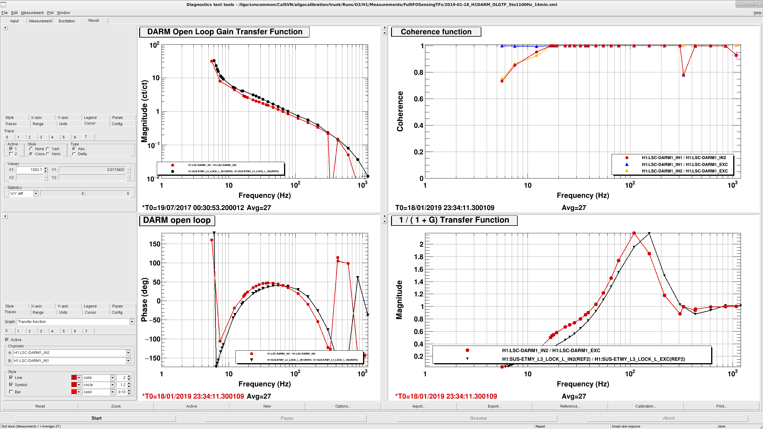
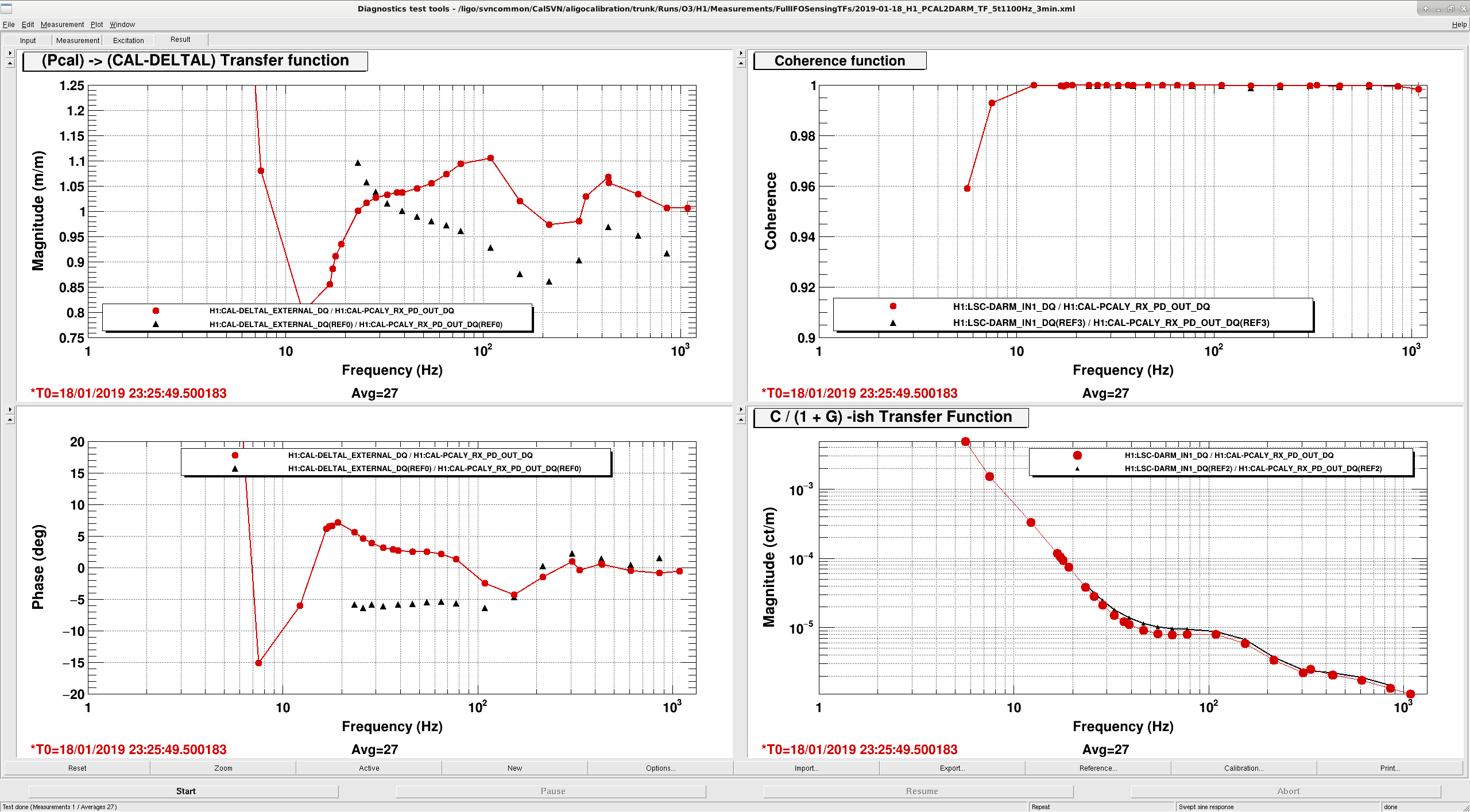
We've had a really tough time keeping the IFO locked over the past week, which has made taking full interferometer calibration measurements difficult. In anticipation / hope that things might get better over the long weekend, here're the location of pre-tuned sensing function sweeps in case anyone gets a good lock stretch:
    /ligo/svncommon/CalSVN/aligocalibration/trunk/Runs/O3/H1/Measurements/FullIFOSensingTFs/
        2019-01-16_H1_PCAL2DARM_TF_5t1100Hz_3min.xml
        2019-01-16_H1DARM_OLGTF_5to1100Hz_14min.xml

To run:
(0) Make sure the IFO has thermalized, letting things settle for ~30 minutes after powering up. The measurements MUST be run in the same, well-thermalized lock stretch.
(1) Request NLN_CAL_MEAS from the ISC_LOCK guardian state (this turns off all calibration lines).
(2) Run each sweep in series; run the PCAL sweep first b/c it's quicker. (You can "cheat" a bit if you're impatient -- when the PCAL gets past ~10 Hz, you can start the DARM OLGTF)
(3) Save the templates with a new date, YYYY-MM-DD but in the same folder.
(4) Request NOMINAL_LOW_NOISE, which will turn the calibration lines back on.

As is indicated by the file names, both measurements together should take about 20 minutes.
Comments related to this report
sheila.dwyer@LIGO.ORG - 16:37, Friday 18 January 2019 (46537)

The sweeps are done and saved with the 18th as the date (19th UTC time).

If the pcal sweep is correct, we are underestimating our range which is what we have been suspecting.

Images attached to this comment
LHO VE
chandra.romel@LIGO.ORG - posted 10:46, Friday 18 January 2019 (46528)
GV11 & GV15 inspections

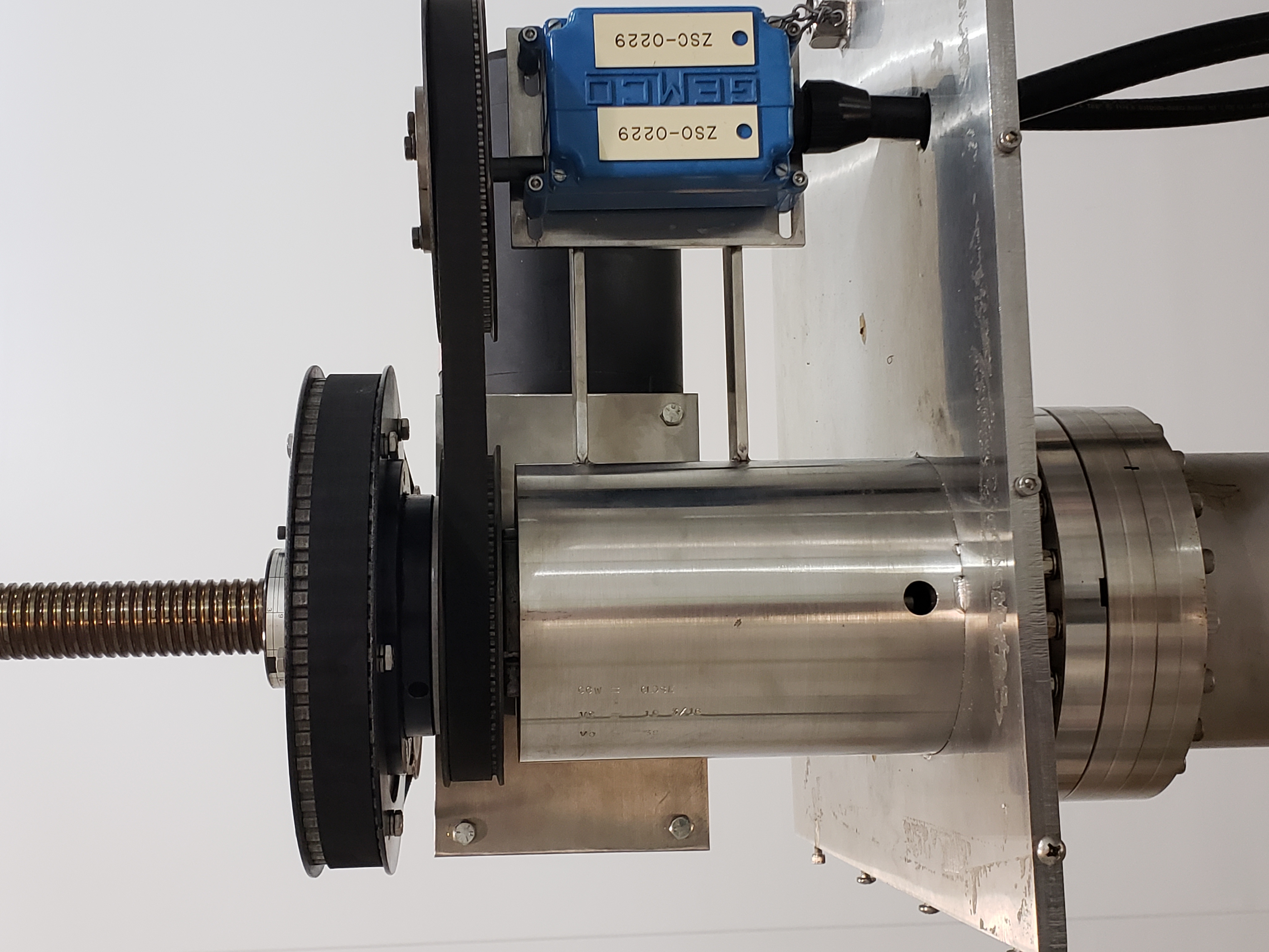
Per Q1800019, I visually inspected H-GV11 and H-GV15 on Dec. 18 to verify that the spindle nut and lock washer are present. Was not able to inspect torque setting without fall protection.

Images attached to this report
LHO VE
chandra.romel@LIGO.ORG - posted 10:39, Friday 18 January 2019 - last comment - 13:56, Tuesday 05 February 2019(46527)
GV12 inspection

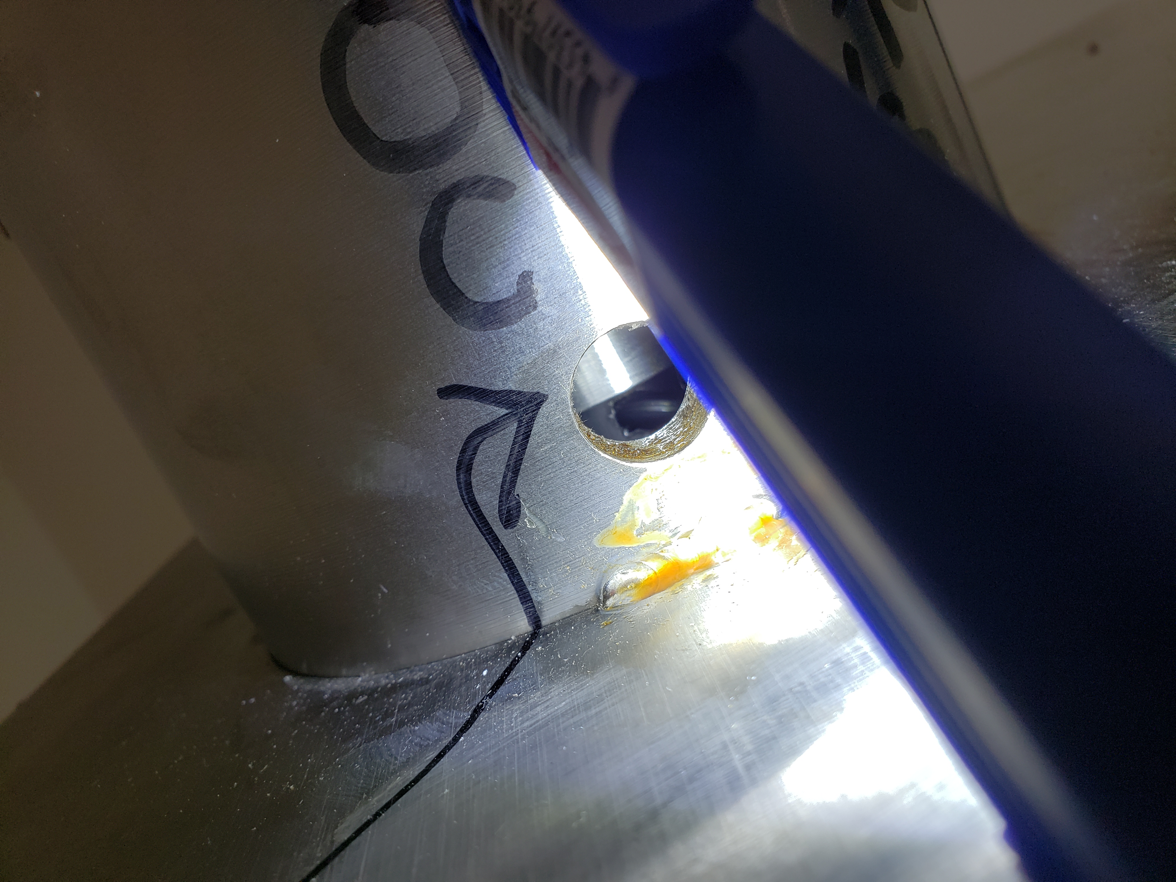
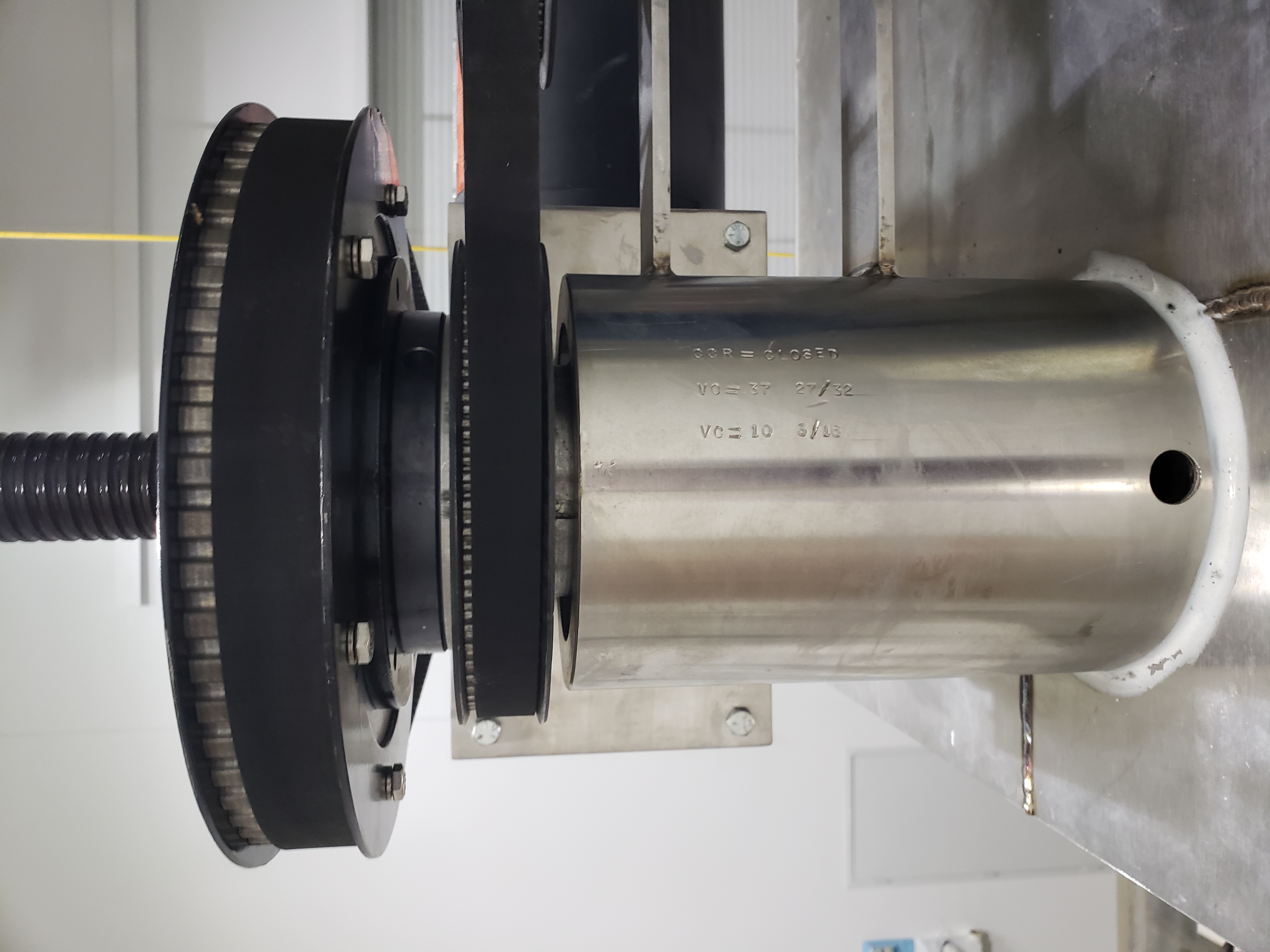
Per Q1800019, I visually inspected H-GV12 on Dec. 19 to verify that the spindle nut and lock washer are present. Was not able to inspect torque setting without fall protection.

Images attached to this report
Comments related to this report
kyle.ryan@LIGO.ORG - 13:56, Tuesday 05 February 2019 (46793)

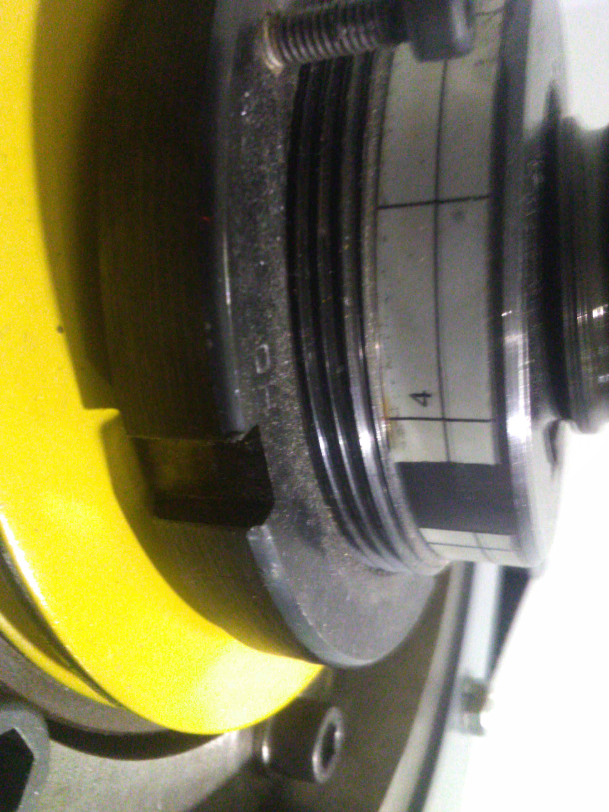
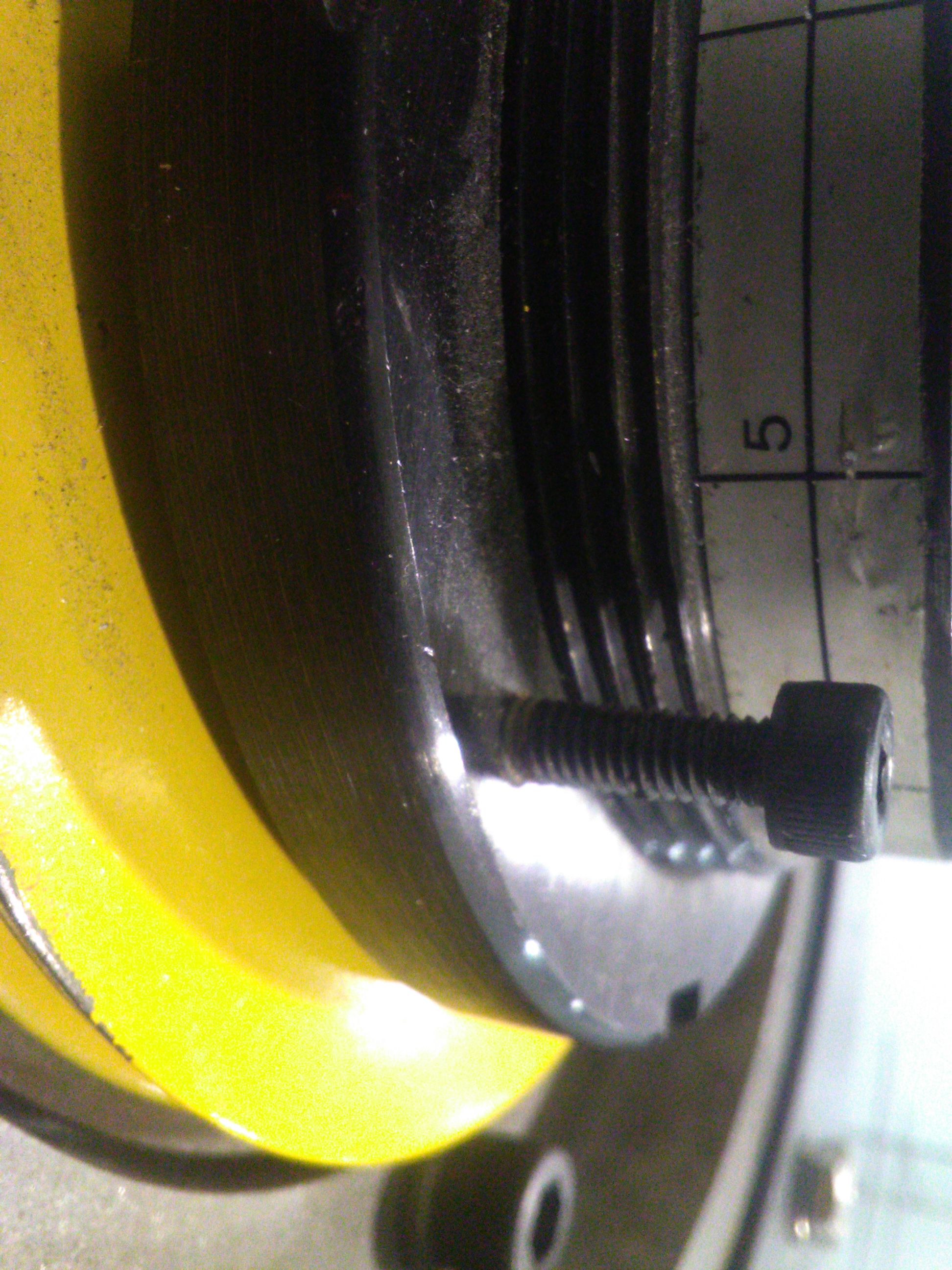
Attached are photos showing the indicated torque pre-load for GV12.  Note that the number of exposed threads may also be important.  

Images attached to this comment
H1 ISC (SEI)
jim.warner@LIGO.ORG - posted 10:02, Friday 18 January 2019 (46478)
Improving 1-10hz HAM ISI to reduce SRCL motion

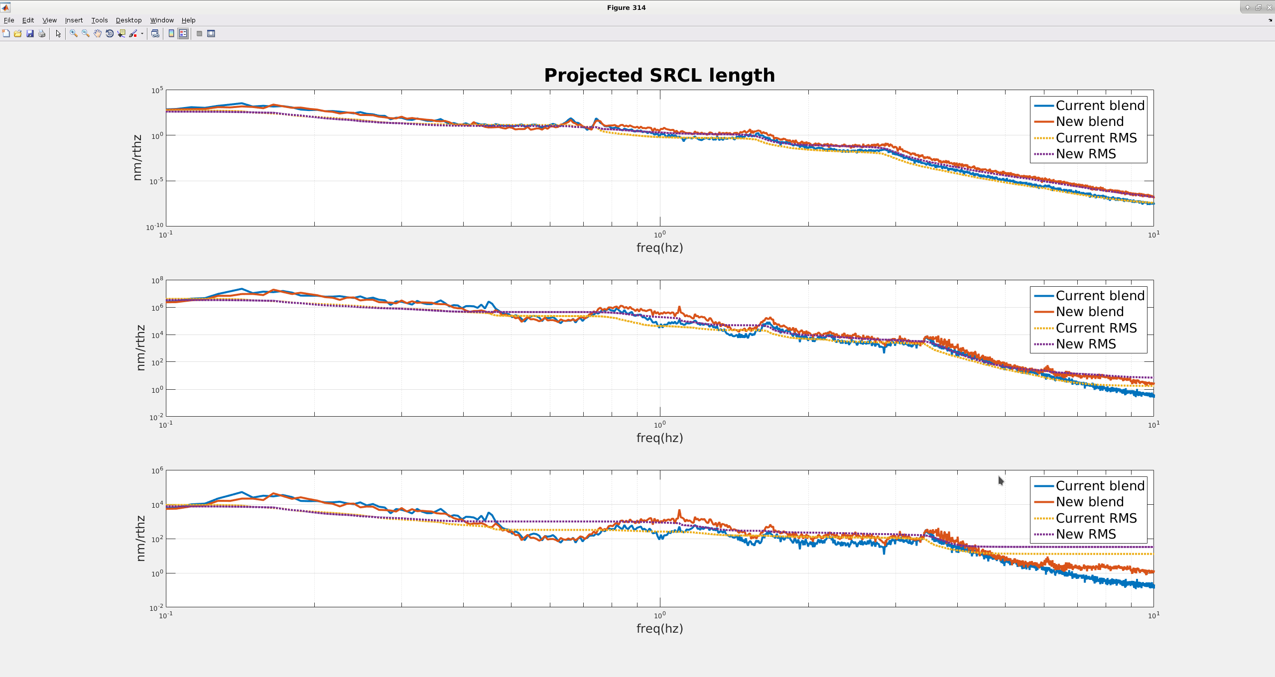
RX/RY motion is typically a limiting factor for ISI suspension point motion. This is because we are limited in lowering the blends by sensor noise, but it might be possible to make different compromises to reduce SRCL motion between 1 and 10 hz, possibly allowing lower SRCL loop gain to reduce SRCL to DARM coupling.

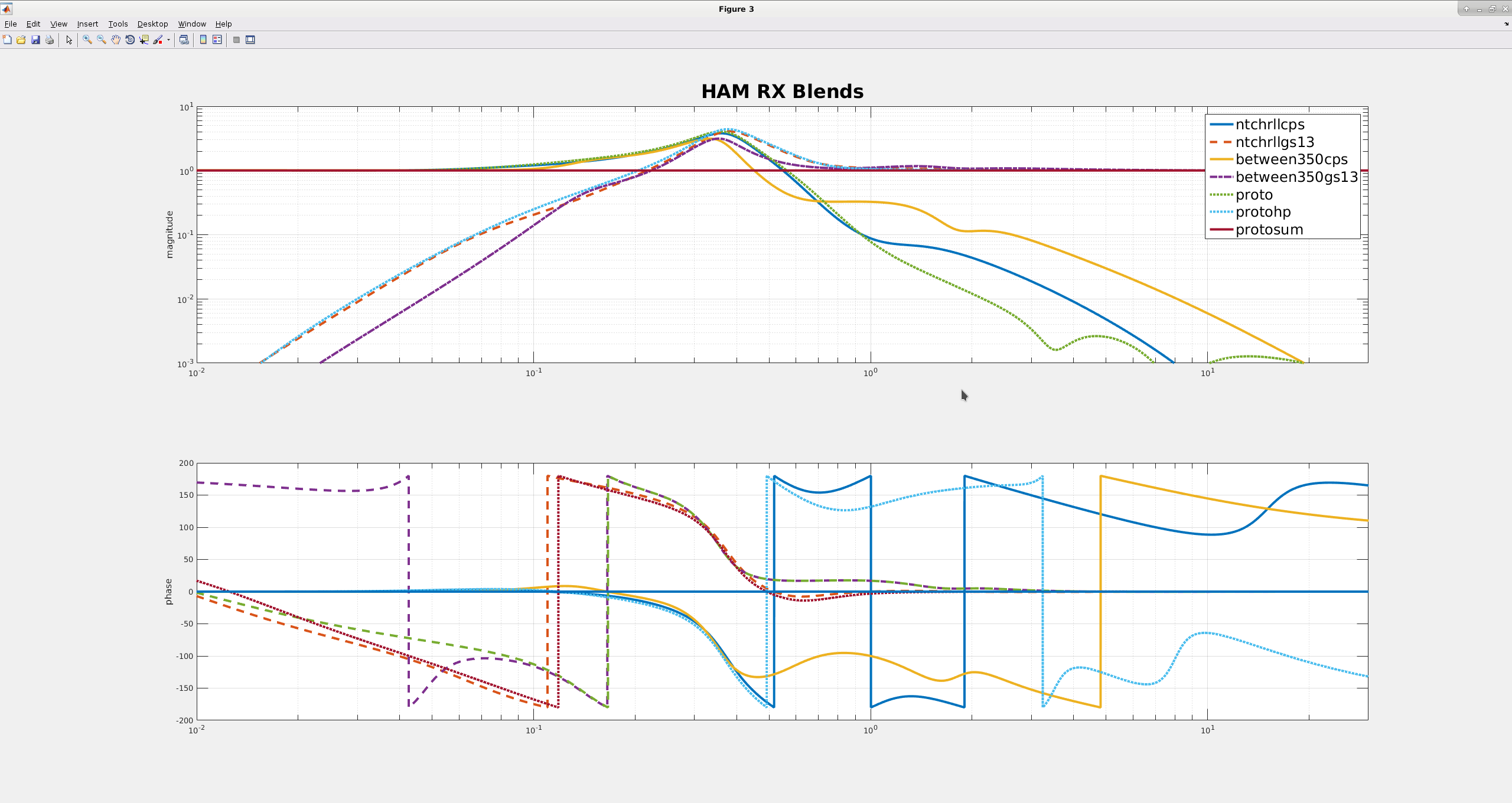
On the HAM ISI, the current RX/RY blends are designed to minimize the blend gain peaking below 1 hz and to avoid injecting rotational GS13 noise into the horizontal loops below .1 hz. This limits how quickly the CPS blends  can roll off above 1 hz, thus limiting the absolute isolation. I've tried to come up with a blend to improve performance above 1 hz, but compromises need to be made to do that. In October, I tried running these blends for a couple of days on HAMs 4&5 RX/RY.

First attached plot shows some spectra comparing a lock on Oct 19 last year (with the "improved blends") to a lock a couple days later (with the low gain peaking blends). The top plot is a reconstruction of the SRCL cavity using the ISI gs13s, which I did by multiplying each optics OAF_SUSPOINT motion timeseries by the appropriate suspension model to estimate each optic's motion (using lsim in matlab), then adding the timeseries together using the coefficients from the OAF_SUSPOINT cavity calculations.  The second plot compares CAL_CS_SRCL for the two locks, this is supposed to be um, but that is clearly wrong, the cavity can't be moving ~1m, so I'm not sure what the calibration is there. The third plot is the SRCL drive on SRM M3. All 3 plots show some improvement over above 1 hz with the more aggressive blends on HAMs 4&5 RX/RY. 

The second attached figure is a bode plot that compares are couple blends for the HAM ISIs. The first two lines (ntchrll...) are the blends that we use currently, which have low gain peaking, but are CPS noise limited, pretty much everywhere. The next two lines (between350...) are the more aggressive blends I tried in October. They inject more GS13 noise at low frequency into the horizontal loops, but didn't keep us from locking, so maybe it's okay. The last three lines are a more aggressive blend I would like to try, guided by the improvements I was able to get by changing blends. The low frequency stuff is pretty similar, the gain peaking is roughly the same, but I gave up above 10hz CPS roll-off to try to get as much improvement as possible between 1-10hz. 

Images attached to this report
H1 PEM
robert.schofield@LIGO.ORG - posted 09:54, Friday 18 January 2019 (46524)
We cant tell if current EY vibration coupling is new since October acoustic injection or not new

It would be interesting to know if the scattering seen at EY is new. Last October I did a quick set of injections to look for major problems - because of limited time these were speaker injections instead of shaker injections and did not probe much below 30 Hz. We did not see any coupling in October. Kara and I went out last night to reproduce the October injections to see if we would have seen vibration coupling if it were at the same level as it is now. The figure shows that we probably wouldnt have noticed the current level of coupling with the injection made in October.

We are set up so that a shaking injection can be made using H1:PEM-EY_GDS_1_EXC. I suggest a standard injection using a bandpass of 1-100 Hz and 50,000 counts for studies to reduce coupling by moving the RMs, offsetting the dither, etc. I have to leave, but Kara is familiar with the system.

Robert, Kara

Non-image files attached to this report
H1 AOS
craig.cahillane@LIGO.ORG - posted 03:45, Friday 18 January 2019 - last comment - 18:49, Sunday 20 January 2019(46520)
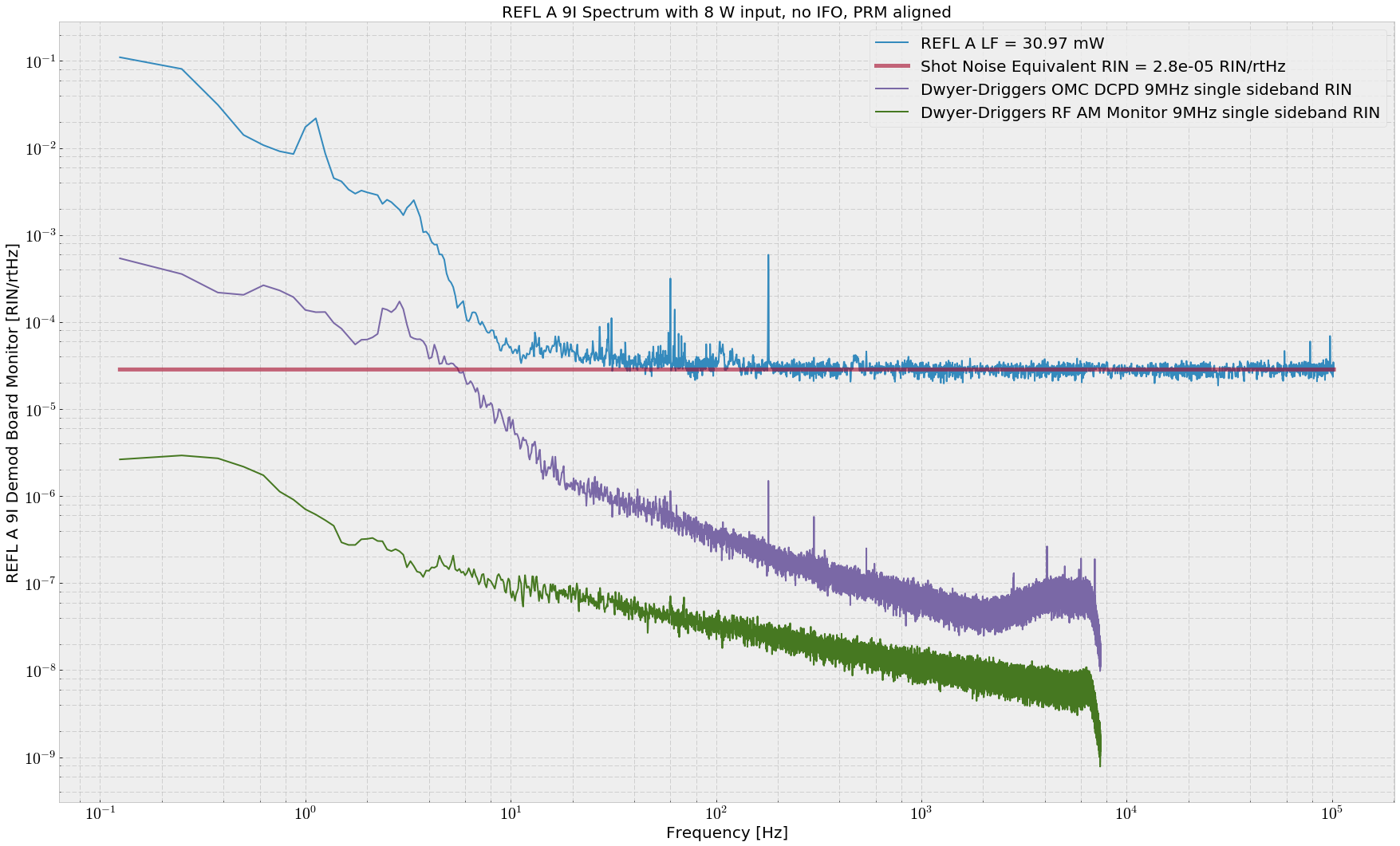
REFL A/B 9I Shot Noise Spectra
Koji, Craig

We became interested in Sheila and Jenne's 9 MHz RIN measurement, and so set out to measure a more complete spectrum of the 9 MHz demodulated REFL PD noise to gain some perspective on the 9 MHz amplitude modulation transmitted through the IMC.

First we shuttered the PSL and measured a full suite of dark noise spectra.  
Then we requested ITMs and SRM misaligned, PRM aligned, and 8 watts of input laser power.  This gave us 30.97 mW on REFL A LF and 28.52 mW on REFL B LF.

This is not a direct comparison of 9 MHz RIN as measured by Jenne and Sheila; their measurement is capable of picking out a single sideband, while ours is the usual carrier and sidebands beatnote.  We'll think about the comparison of each measurements' RIN.
Non-image files attached to this report
Comments related to this report
daniel.sigg@LIGO.ORG - 09:45, Friday 18 January 2019 (46525)

Units in the plot? Not sure how you distinguish shot noise from RFAM with a measurement at just one incident power.

craig.cahillane@LIGO.ORG - 18:49, Sunday 20 January 2019 (46551)
H1 IOO (IOO)
cheryl.vorvick@LIGO.ORG - posted 03:24, Friday 18 January 2019 - last comment - 18:02, Monday 21 January 2019(46521)
measuring the beam spot location on CW1, the first optic in the IO Faraday

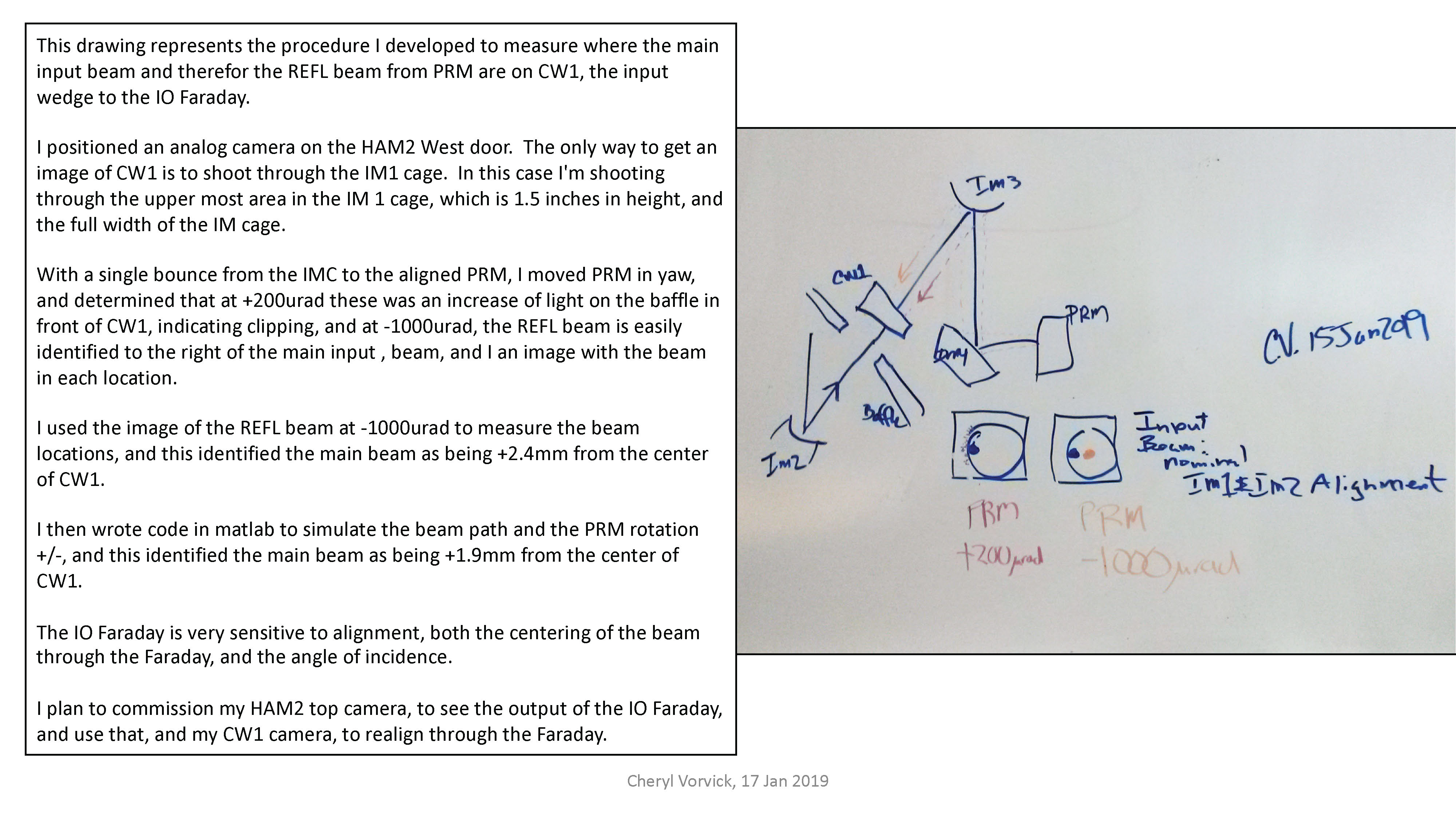
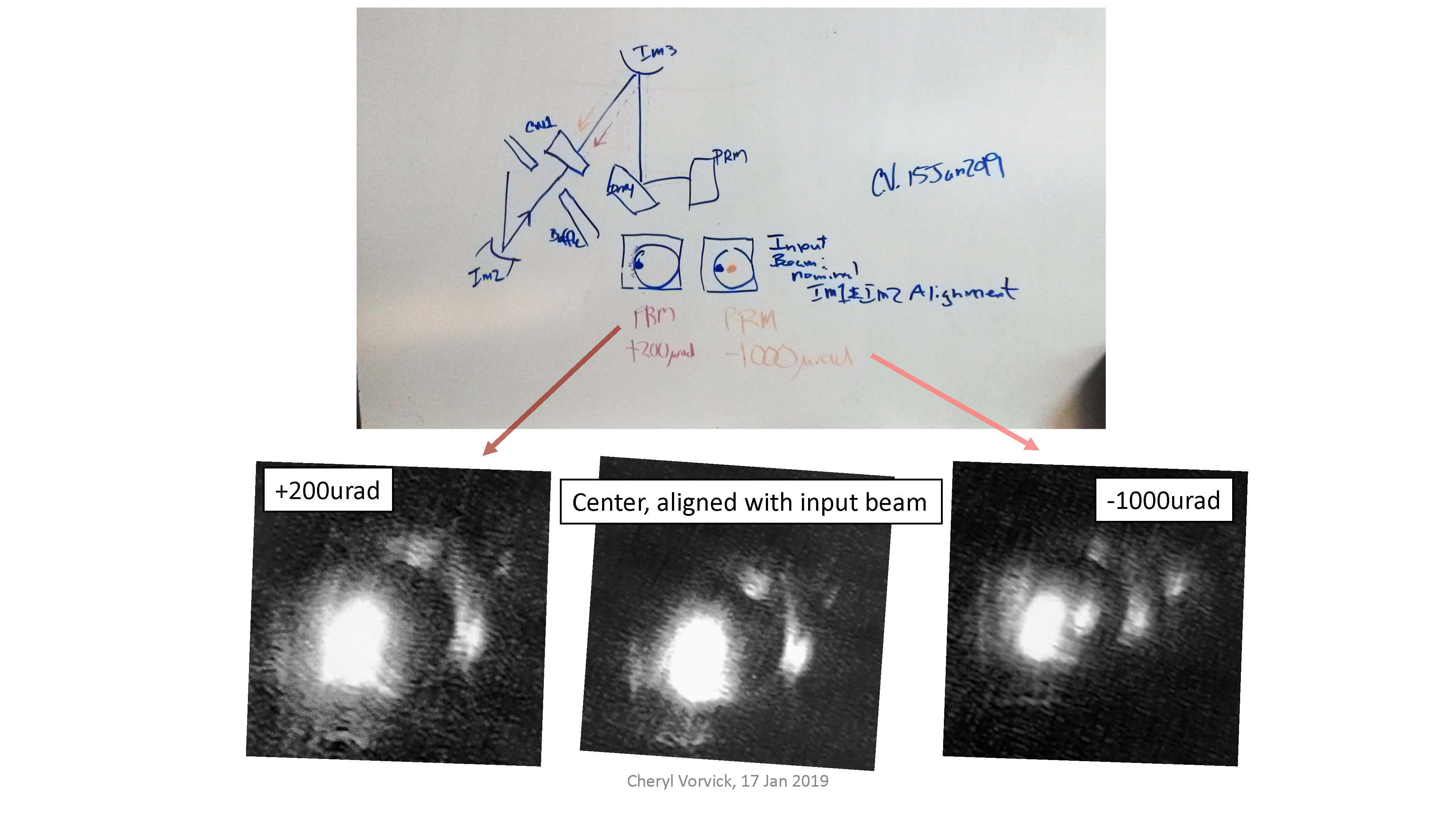
I put a camera on the HAM2 West door, which looks at CW1, the back side of the wedge, which is carefully aligned to shoot through the IM1 tower.

This week I developed a procedure to use PRM with a single bounce, to move the REFL beam on CW1, and and look for clipping.  The procedure revealed that when PRM is in it's aligned position plus an additional 200urad in yaw, there's an increase in light on the baffle, consistent with the REFL beam starting to clip.  With PRM at -1000urad, the REFL beam is clearly seen on CW1 to thr right of the main input beam.

Using the image and a beam path simulation I wrote in matlab, I've measured the main input beam to be between 2mm and 3mm from center.

I need to adjust my HAM2 top camera to improve the view of the IO Faraday output side, which is planned for next Tuesday, in order to realign through the Faraday, to correct the mis-centering at both the input and output Calcite Wedges.


compared to the main input beam, which I've used to identify the location of the main input beam on the wedge.  A diagram and images attached.

Images attached to this report
Comments related to this report
cheryl.vorvick@LIGO.ORG - 03:36, Friday 18 January 2019 (46522)

I've written up how I measured beam positions using images.  My measurements from the image are consistently about 20% larger than the beam path simulation.  Given the uncertainties in both methods, and and uncertainties in the beam path, I'm not concerned about the 20% difference. 

Both measuring methods identify the main input beam as 2+ mm from the center of CW1, which will effect the IO Faraday performance.

Non-image files attached to this comment
cheryl.vorvick@LIGO.ORG - 18:02, Monday 21 January 2019 (46557)

I've recalculated the centering of the main beam on CW1, after Keita identified my original calculation as low by about 10%.

My updated calculation shows the main beam as +2.2mm from the center of CW1, where I had originally posted +1.9mm.

The measured value from the image is +2.4mm, so the updated value of +2.2mm is now within 10% of the measured value.

Attachment is updated to show the change.

Non-image files attached to this comment
H1 ISC (ISC)
craig.cahillane@LIGO.ORG - posted 04:35, Thursday 17 January 2019 - last comment - 11:37, Friday 18 January 2019(46495)
Locking tonight
Koji, Craig

- We ran the RF9 modulation depth change test Sheila asked us to do.  Koji will post an alog about those results.

- Koji had me lock the OMC with PZT2 at only 2 volts, rather than the usual ~40 V, for +9MHz 9th order HOM considerations.

- We measured the PRCL OLG after full thermalization at high power, and got a 30 Hz UGF.  This seems much lower than what was reported by Jenne a week ago.

- I carried the laptop in with me as I made my way down to the PSL racks.  
This time, I was able to make it without causing a lockloss, but when I got there the SR785 GPIB was gone, and when going to get it from the squeezer bay, while walking between HAM2 and HAM3 I killed the lock.
The area directly in front of the door in the LVEA, between HAM2 and HAM3, is the most sensitive to walking around, according to IMC_F.  Stepping on the lower tier floor directly inside of the LVEA door seemed to produce the largest response in IMC_F, including during my first excursion to the PSL racks.

- We reached nominal low noise again, but lost it within ten minutes, probably due to some CHARD, DHARD pitch ringup.  

- We reach NLN a third time, and this time held it for two hours, during which I was able to get to the PSL racks and measure all CARM spectra.  We eventually lost lock due to a super slowly growing ASC 0.9 Hz oscillation (lost lock about an hour after the ringup started).

- Had to readjust TMSY alignment in pitch significantly to get the guardian to continue locking in FIND_IR.
Comments related to this report
koji.arai@LIGO.ORG - 05:17, Thursday 17 January 2019 (46496)

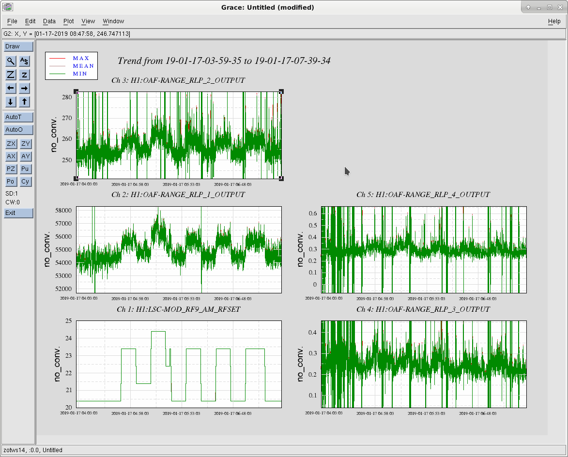
We started the modulation of the modulation depth from 4:48 UTC. I'd say the data from 5:43 UTC is clean. (Attachment 1 Left Bottom Plot). The modulation power for 9MHz was switched between 20.4dBm (LOW) and 23.4dBm (HIGH). We could clearly see that the DARM noise power in each monitored frequency band (Other plots in Attachment 1, RLP1: 10-20Hz, RLP2 20-29Hz, RLP3 38-60Hz, RLP4 60-100Hz, RLP5 100-450Hz). Interestingly, the change of the noise power is visible even at the lower frequency (10-20Hz) although the change is small (~4%) and difficult to confirm with the power spectrum.

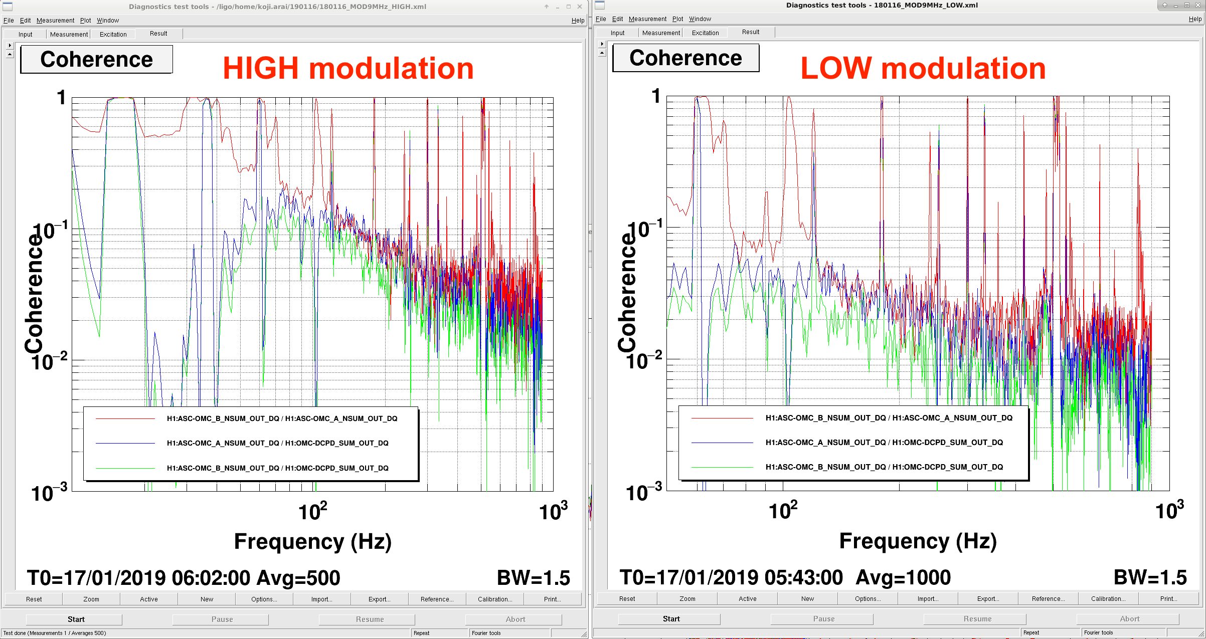
The coherence between DCPDSUM and OMC QPDs (as well as the coherence between the QPDs) were measured both in the HIGH and LOW states.

Attachment 2:
High modulation depth: 17/1/2019 6:02:00 UTC~ 1HzBW 500AVG
Low modulation depth: 17/1/2019 6:15:00 UTC~ 1HzBW 500AVG

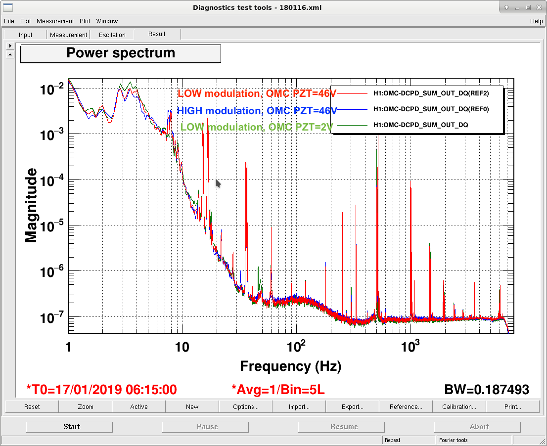
The comparison of the OMC DCPD spectra (=DARM) is shown in Attachment 3. Here we added another plot with the low modulation and OMC PZT Voltage around 0 (i.e. One FSR away from the nominal locking point). This gave us ~85Mpc, probably because of slightly better rejection of 9MHz SB by the OMC (not so certain).

We took the relatively glitch free data for the high modulation state between 17/1/2019 7:01:45UTC~7:13:45UTC.

Images attached to this comment
koji.arai@LIGO.ORG - 17:02, Thursday 17 January 2019 (46517)

As the OMC QPD signal contains the carrier TEM00 too, the coherence between DCPD and QPDs can not be completely zero. I have not yet estimated the quantitative limit what the minimum coherence we can realize by eliminating the 9MHz noise.

sheila.dwyer@LIGO.ORG - 11:37, Friday 18 January 2019 (46529)

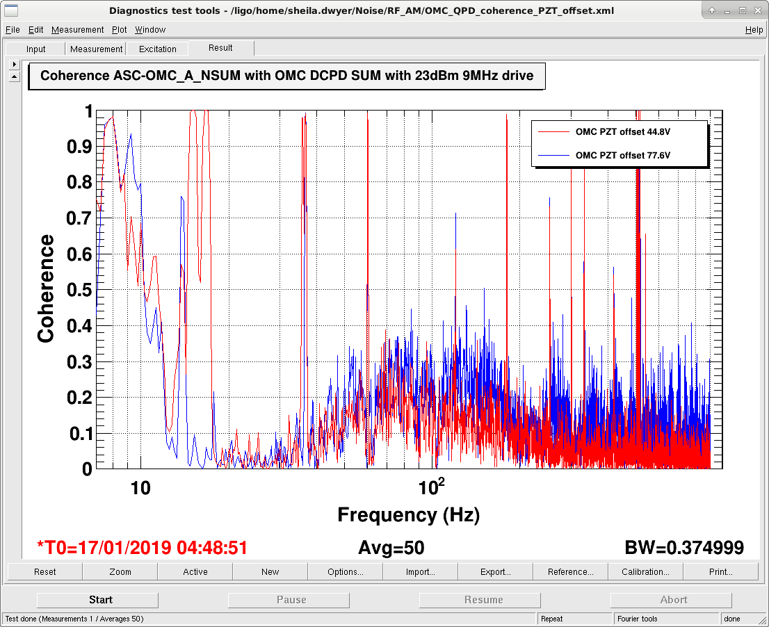
Here's a comparison of two times when the 9 MHz modulation depth was increased to have 23dBm at the driver, with different OMC PZT offsets. 

The first time is Jan 16th at 6:40:30 UTC, with an OMC PZT2 monitor readback of 77.6 V, the second time is Jan 17th at 4:48:51 UTC with PZT2 at 44.8 Volts. 

The coherence between the OMC QPD and the DCPD's is lower for the lower PZT voltage, which fits with Koji's model that the 9 MHz is reaching the DCPD's through the higher order mode which has an OMC resonance close to the carrier resonance.

Images attached to this comment
H1 SQZ (SQZ)
nutsinee.kijbunchoo@LIGO.ORG - posted 18:17, Wednesday 16 January 2019 - last comment - 14:53, Friday 18 January 2019(46489)
Comparing the NLG using two different methods

We are still trying to nail down our non-linear gain measurement. Here's a comparison between two methods:

1) MIT method:

nlg = ((sqrt(pMax/pMin) + 1)/2)^2

2) ANU method:

nlg = pMax/pUnamp

pUnamp is seed transmission measured outside nlg region as I scan the OPO cavity (temperature set to ~51C, green blocked). Which is an unamplified seed power.

I took nlg measurement with data from StripTool and oscilloscope. The result are consistent within 10% between the two methods and two devices. 


Pump input to coupler: 20mW

Pump reflected (OPO off resonance): 2.7 mW

Seed input to coupler: 1 mW


StripTool (IR trans PD): max = 0.0063 mW, min = 0.0019 mW, DN = -6.8e-5 mW

Scope (IR trans PD): max = 142 mV, min = 47.6mV, DN 8mV

Seed trans unamplified: StripTool = 0.003 mW, Scope = 76.4 mV


  StripTool Oscilloscope
MIT Method 1.958 2.015
ANU Method 2.1 1.85


Comments related to this report
nutsinee.kijbunchoo@LIGO.ORG - 14:53, Friday 18 January 2019 (46532)

Note that 20dB attenuator is off during this measurement.

H1 ISC (ISC)
georgia.mansell@LIGO.ORG - posted 00:55, Wednesday 16 January 2019 - last comment - 16:25, Friday 18 January 2019(46461)
SRCL feedforward tuning

Craig, Georgia, Danny, Sheila

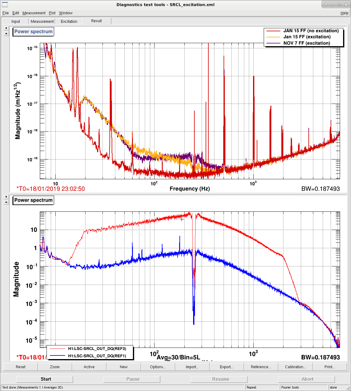
We have re-tuned the SRCL feedforward for 30 W interferometer configuration. The updated feedforward reduced SRCL coupling to DARM from 60Hz to 500Hz (driven measurement shown in final attachment).

We measured the transfer function from SRCL to DARM without feedforward, and from the SRCL-FF path to DARM, using templates found here:

/opt/rtcds/userapps/release/lsc/h1/scripts/feedforward/

We then used Craig's ipython notebook to fit these transfer functions and calculate the feedforward filtering required to cancel SRCL noise in DARM. The notebook is found here:

/ligo/home/craig.cahillane/Git/Feedforward/SRCL2DARMfeedforward.ipynb

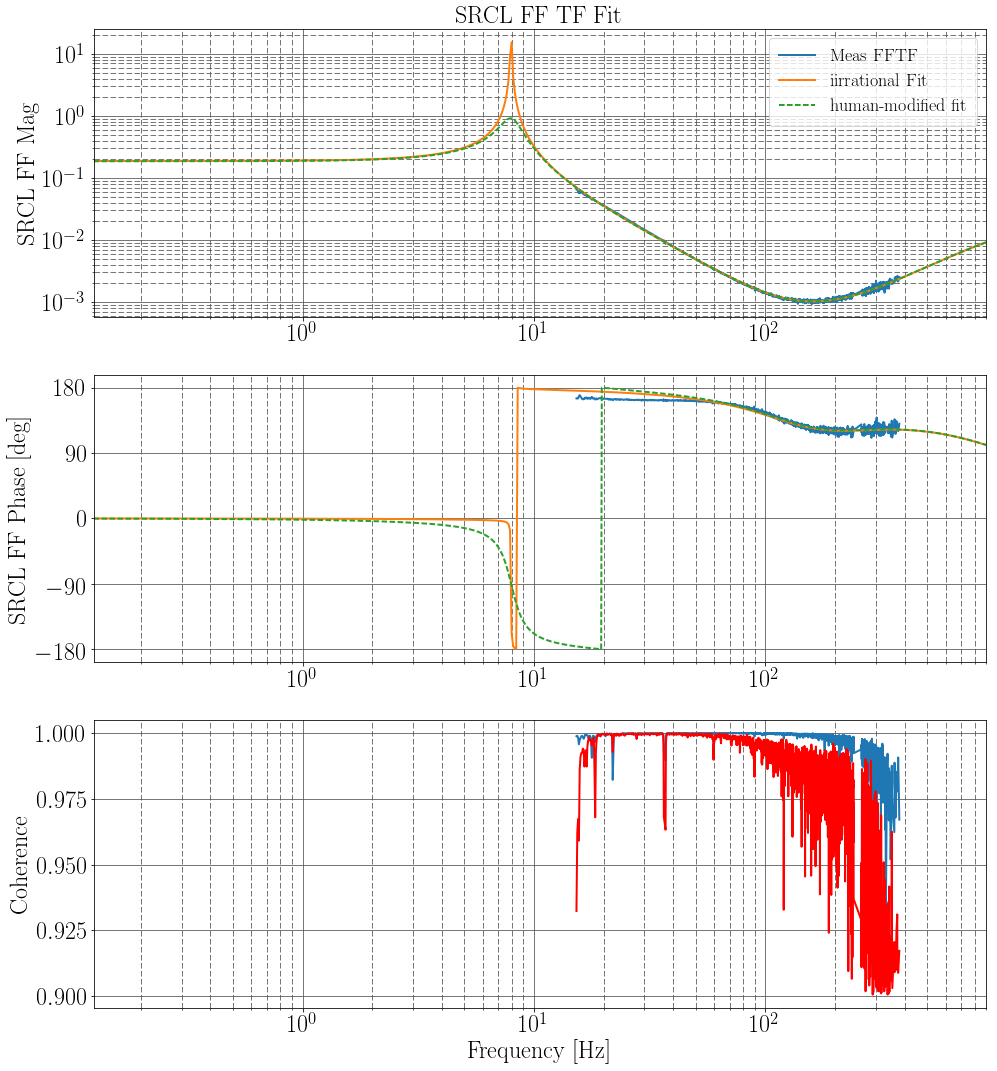
This notebook uses iirrational to fit the transfer functions. We added some human tweaking to the fit to minimise the resonant peak at ~8Hz. First attachment shows the data (blue), iirrational's fit (orange), and the human-modified fit that was implemented in the feedforward filter (green). Note that the fit to the phase of the TF is not good below 60 Hz, so perhaps there is room for iterative improvement on these filters.

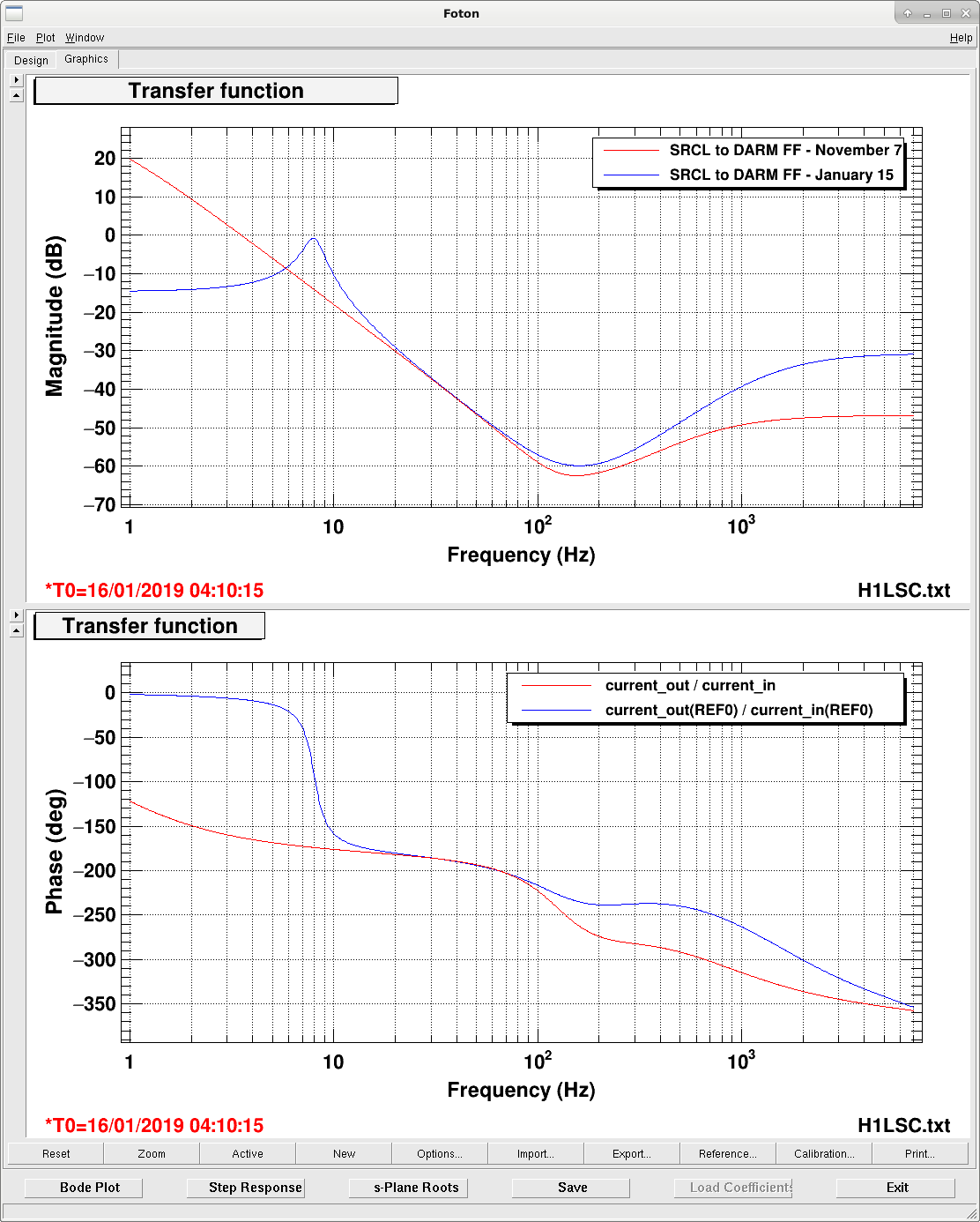
The second attachment shows the old SRCL-FF filter (Nov7) compared to our new filter (Jan15).

The final attachment shows the SRCL to DARM coupling reduction: yellow is DARM (and SRCL) with no excitation, blue is with the old feedforward, purple is the new feedforward.

Images attached to this report
Comments related to this report
daniel.vander-hyde@LIGO.ORG - 16:25, Friday 18 January 2019 (46535)

Attached is a similar measurement but on 1/18/2019. Not exactly the same excitation but close enough to show that with the same feed forward filter the SRCL noise is higher (between 60 and 450 Hz) than it was when we took this measurement a couple of days ago.

Images attached to this comment
H1 CAL (CAL, INJ)
jameson.rollins@LIGO.ORG - posted 15:19, Tuesday 15 January 2019 - last comment - 09:24, Saturday 19 January 2019(46407)
new hardware injection front end model installed: h1calinj

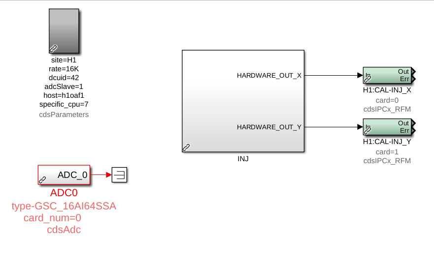
A new h1calinj model has been installed on the h1oaf1 machine.  This model will hold all front-end injection handling logic, including the injection EXC test points, under the channel prefix "H1:CAL-INJ_".  The existing injection handling code in the h1calex model ("H1:CAL-PINJX_") has been left as is for now to facilitate transitioning and testing.

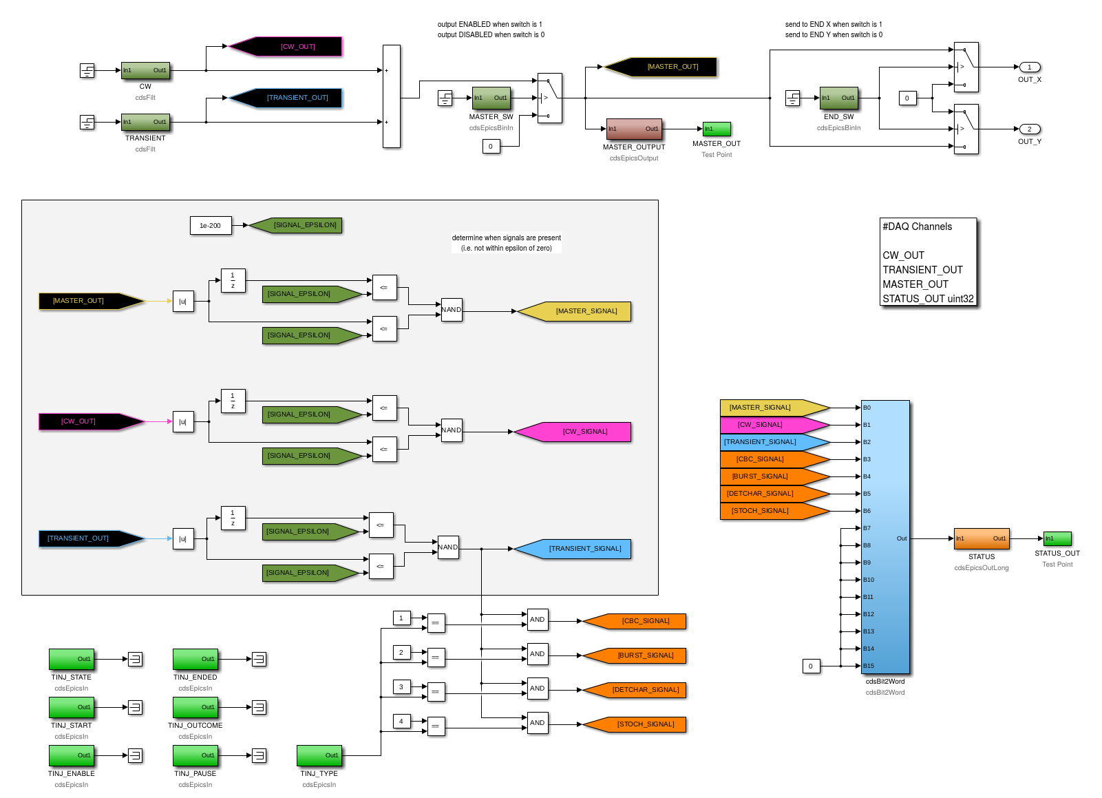
The first two attached images are of the top-level contents of the new h1calinj model, and of the contents of the "INJ" CAL_INJ_MASTER2 library part that contains all the core logic.  The top of the latter shows the main injection signal flow.  The two "CW" and "TRANSIENT" filter banks at the upper left hold the EXC inputs and calibration filters for the continuous-wave (CW) and transient (TRANSIENT) injection inputs respectively.  The outputs of the two modules are summed and the overall "MASTER" output goes through an output switch ("MASTER_SW"), and then finally a switch ("END_SW") that determines which of calex or caley receives the injection signal ("H1:CAL-INJ_{X,Y}" via cdsIPCxRFM).  Below the main signal path is logic to determine the presence of signals at various points in the injection path, and bundle that info into a single status word ("STATUS_OUT").

IPC receivers for the INJ_MASTER output sent from h1calinj (H1:CAL-INJ_{X,Y}) were added to the h1calex and h1caley models.  EPICS and acquired test point monitors of the received signals were also added.

NOTE: a single 2**14 Hz, 61 us cycle delay will be added to the injection path because of the IPC needed to carry the signal from the vertex to the ends.

The new acquired fast channels are:

The STATUS channels (the H1:CAL-INJ_STATUS_OUT_DQ uint32 fast channel and the H1:CAL_INJ_STATUS slow channel) have the following bits:

  1. MASTER
  2. CW
  3. TRANSIENT
  4. CBC
  5. BURST
  6. DETCHAR
  7. STOCH

A value of zero (0) indicates no signal of the specified type is present, and a value of one (1) indicates the presence of the specified signal.

The h1calinj model also holds the "TINJ" EPICS status bits, nominally set by the INJ_TRANS guardian node.  NOTE: the "H1:CAL-INJ_TINJ_" EPICS records were previously hosted by the ext_alert_ioc.py soft IOC running on the h1fescript0 machine.  The records were removed from the soft IOC and the process was restarted.

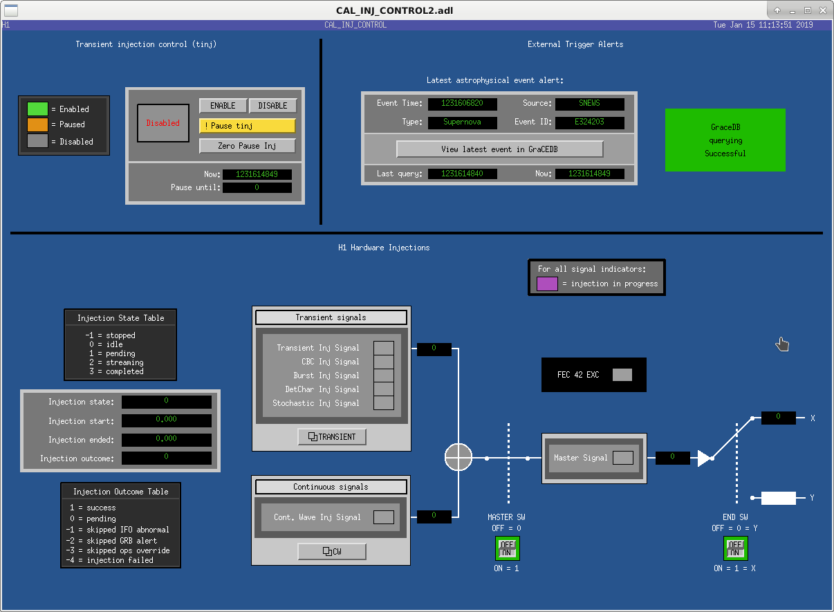
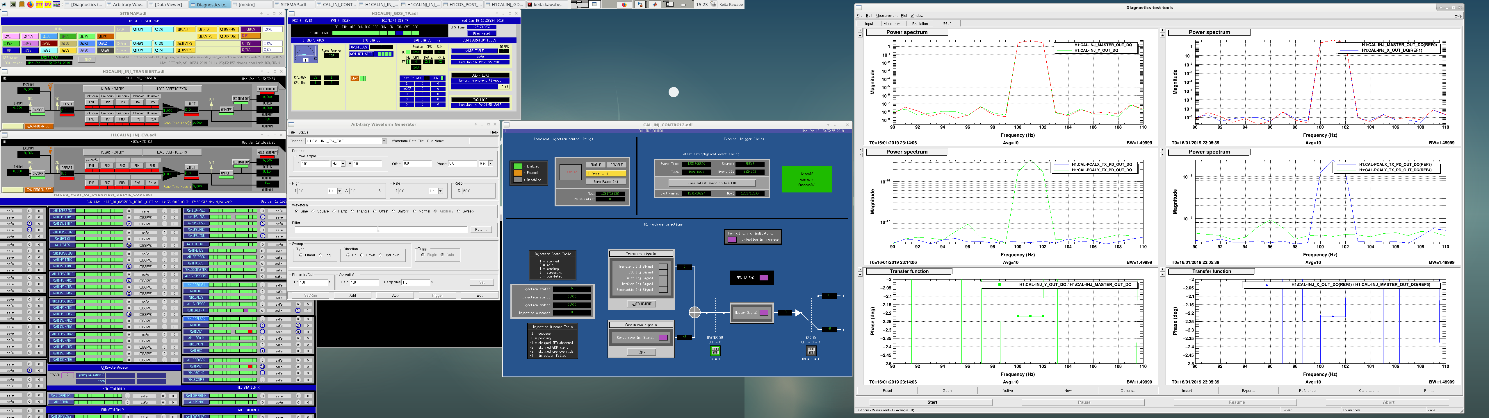
The final image attached is a new MEDM screen CAL_INJ_CONTROL2.   All functionality and status bits in the h1calinj model, and the monitors in h1calex and h1caley, are exposed.

As mentioned above, all the existing INJ infrastructure remains in place.  We leave it up to the INJ group to update the INJ_TRANS guardian, the psinject process, downstream monitors, etc.  We would like to schedule the removal of the old INJ infrastructure as soon as possible,

Images attached to this report
Comments related to this report
keita.kawabe@LIGO.ORG - 15:46, Wednesday 16 January 2019 (46480)

New MEDM screen is now accessible from the sitemap (cal-> hwinj ctrl). Old one is still there as "hwinj ctrl old".

I briefly tested the new frontend.

  • TRANSIENT INJ Signal bit of H1:CAL-INJ_STATUS responded correctly to excitation as well as an offset in H1:CAL-INJ_TRANSIENT filter module.
  • CW INJ Signal bit of H1:CAL-INJ_STATUS responded correctly to excitation as well as an offset in H1:CAL-INJ_CW filter module.
  • MASTER Signal bit of H1:CAL-INJ_STATUS responded correctly to excitation as well as an offset in either INJ_TRANSIENT or INJ_CW filter module.
  • Excitation bit of H1:FEC-42_STATE_WORD only responded to excitations but not offsets (of course).
  • H1:CAL-INJ_END_SW=1 or 0 correctly delivered the MASTER_OUT signal to h1calex or h1caley model (monitor points are H1:CAL-INJ_X_OUT and H1:CAL-INJ_Y_OUT).
  • Time delay from MASTER_OUT to h1calex and h1caley was  61.035us, which is almost exactly 1/(2^14Hz). This was measured by injecting sine wave at 101Hz to CW and measuring the transfer function from MASTER_OUT to X_OUT or Y_OUT.
  • H1:CAL-INJ_X_OUT or Y actually does go to PCAL laser power (done by looking at H1:CAL-PCALX_TX_PD_OUT or Y).

No surprise in the above. See the screen shot.

One surprise was that I had some problem loading filters to the new model using foton. Jamie and Rolf are working to figure it out.

Images attached to this comment
keita.kawabe@LIGO.ORG - 15:30, Friday 18 January 2019 (46533)DetChar, INJ

(Jamie, Keita)

Existing filters in CAL-PINJX_TRANSIENT filter module were  copied over to the new CAL-INJ_TRANSIENT filter and loaded successfully, and the settings represented by the attached screen were put in SDF as safe.

Transient injection group should test the new infrastructure as soon as possible. The new channel to inject is H1:CAL-INJ_TRANSIENT_EXC.

Note that, as of now, the filter is automatically loaded after the model restart as expected, but you cannot reload as far as the model keeps running. CDS group is still investigating, but in the mean time if you need to load the filter, contact the site (e.g. myself) and we'll schedule to restart the model.

Images attached to this comment
david.barker@LIGO.ORG - 09:24, Saturday 19 January 2019 (46542)

I've opened FRS-12175 to cover the problem loading h1calinj's filter file.

LHO VE
chandra.romel@LIGO.ORG - posted 09:08, Tuesday 15 January 2019 - last comment - 10:14, Friday 18 January 2019(46418)
LVEA walk through - GV4 inspection & HAM7 AIP

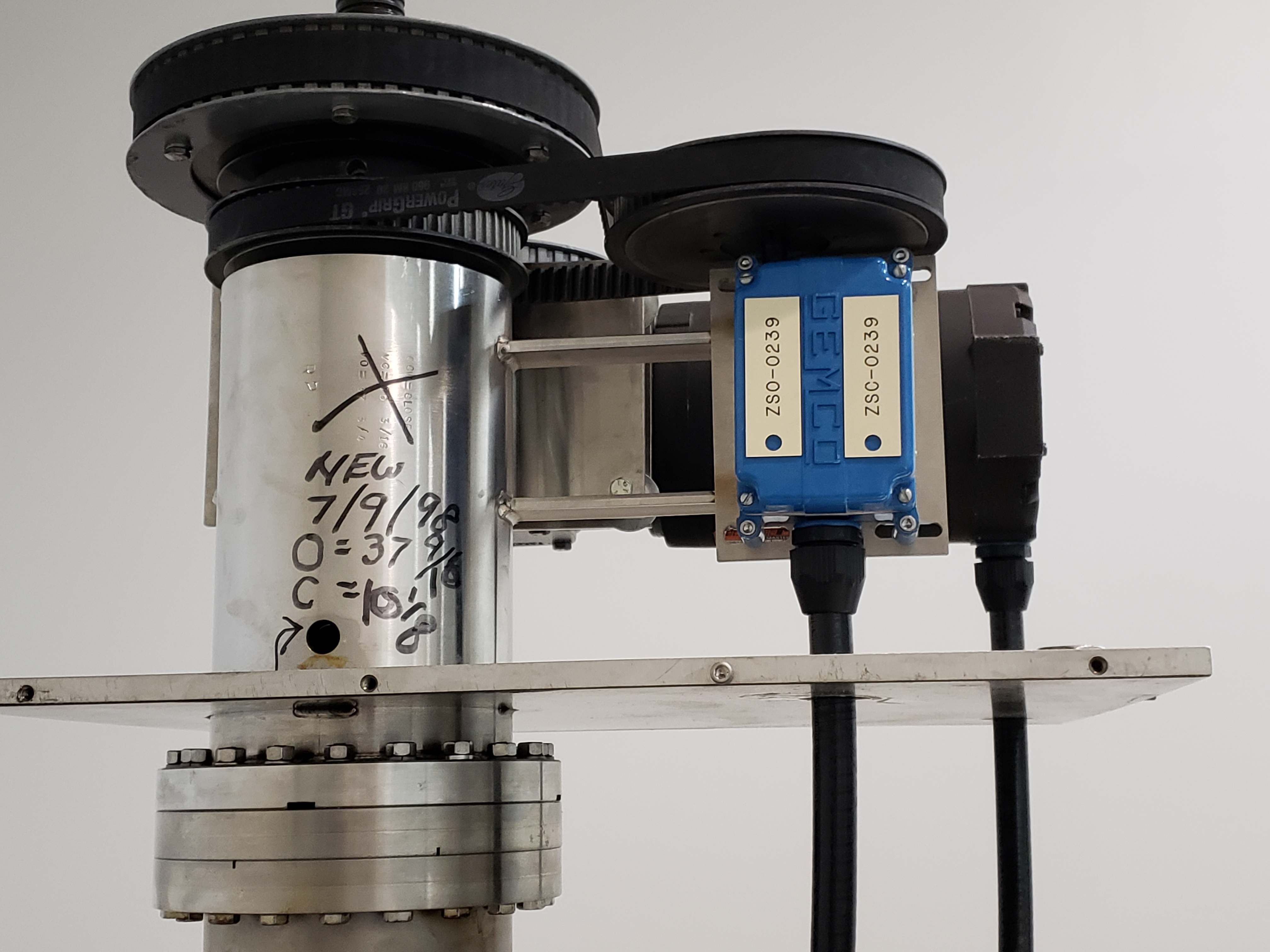
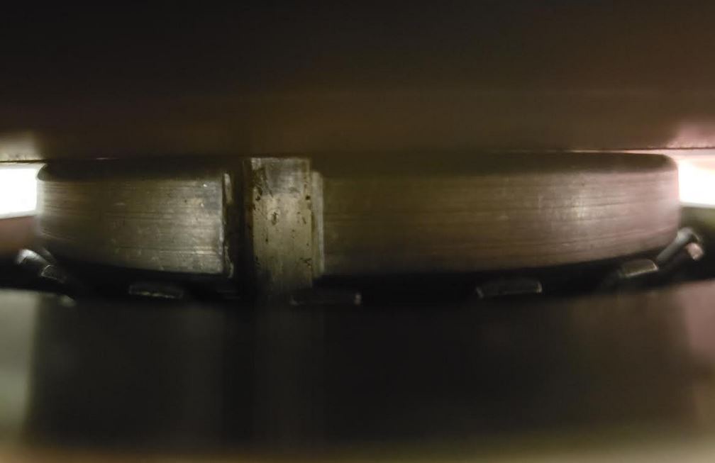
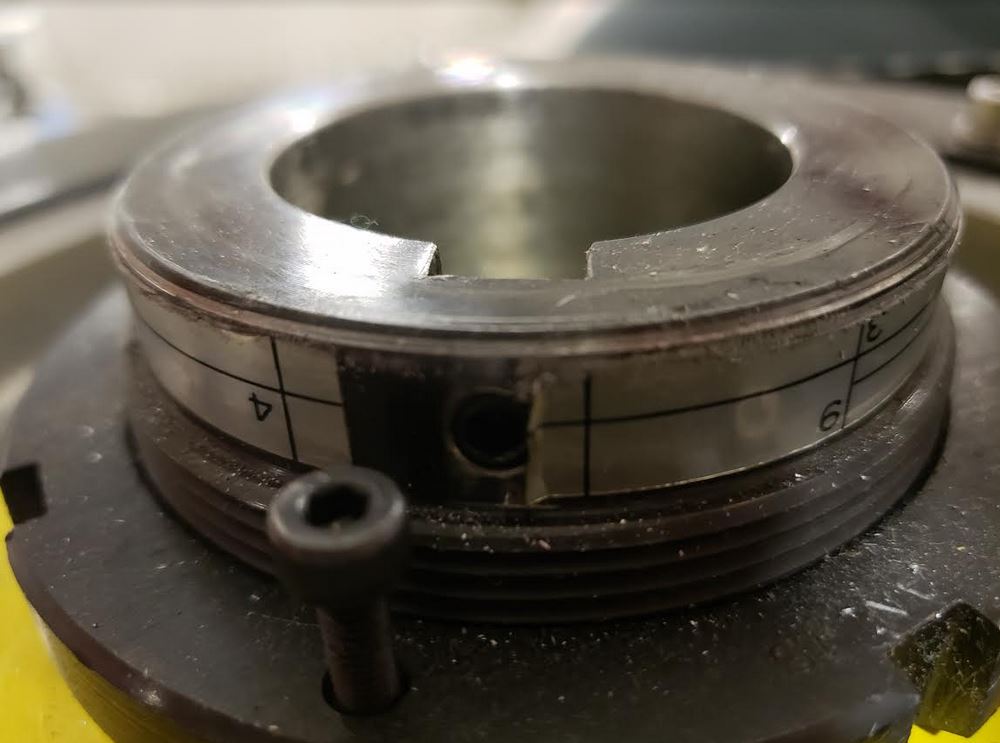
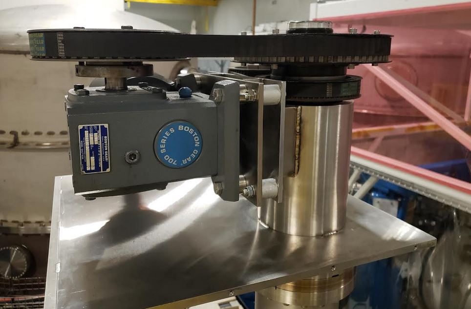
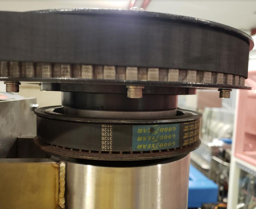
Visually inspected GV4 and found it is equipped with a retaining nut and anti-rotation locking washer. Torque setting on pulley nut as seen in attached photo.

Again I tapped on HAM 7 annulus ion pump but the red overload light remained on, so I turned off the power supply.

Images attached to this report
Comments related to this report
chandra.romel@LIGO.ORG - 10:14, Friday 18 January 2019 (46526)

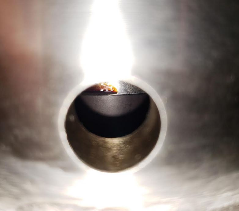
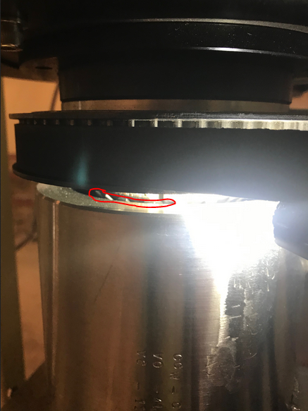
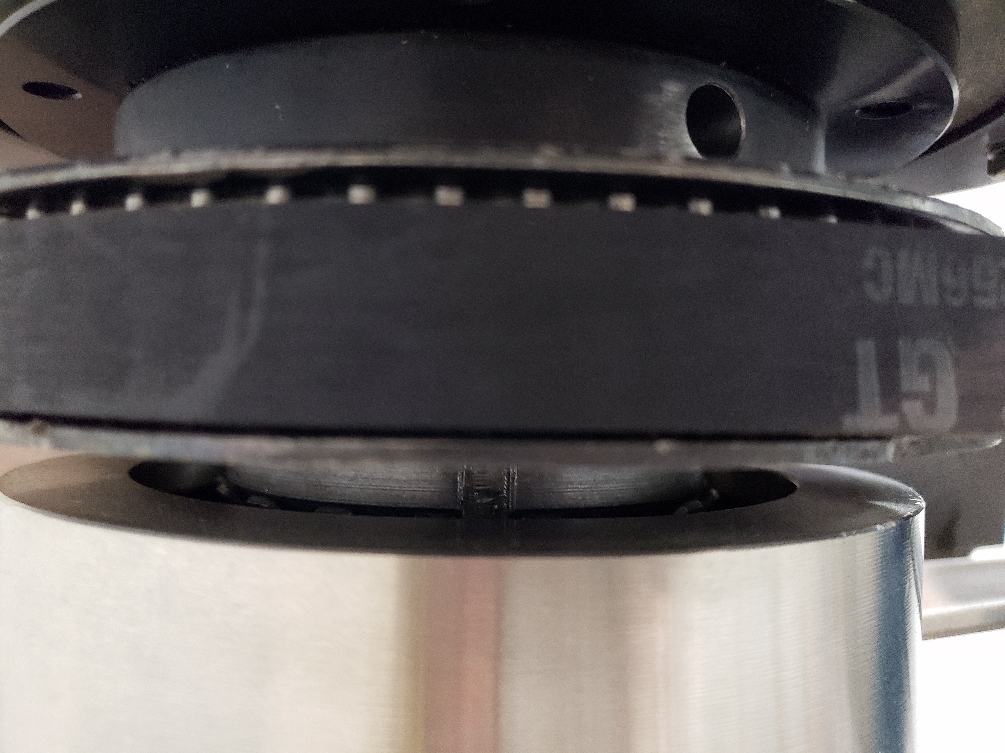
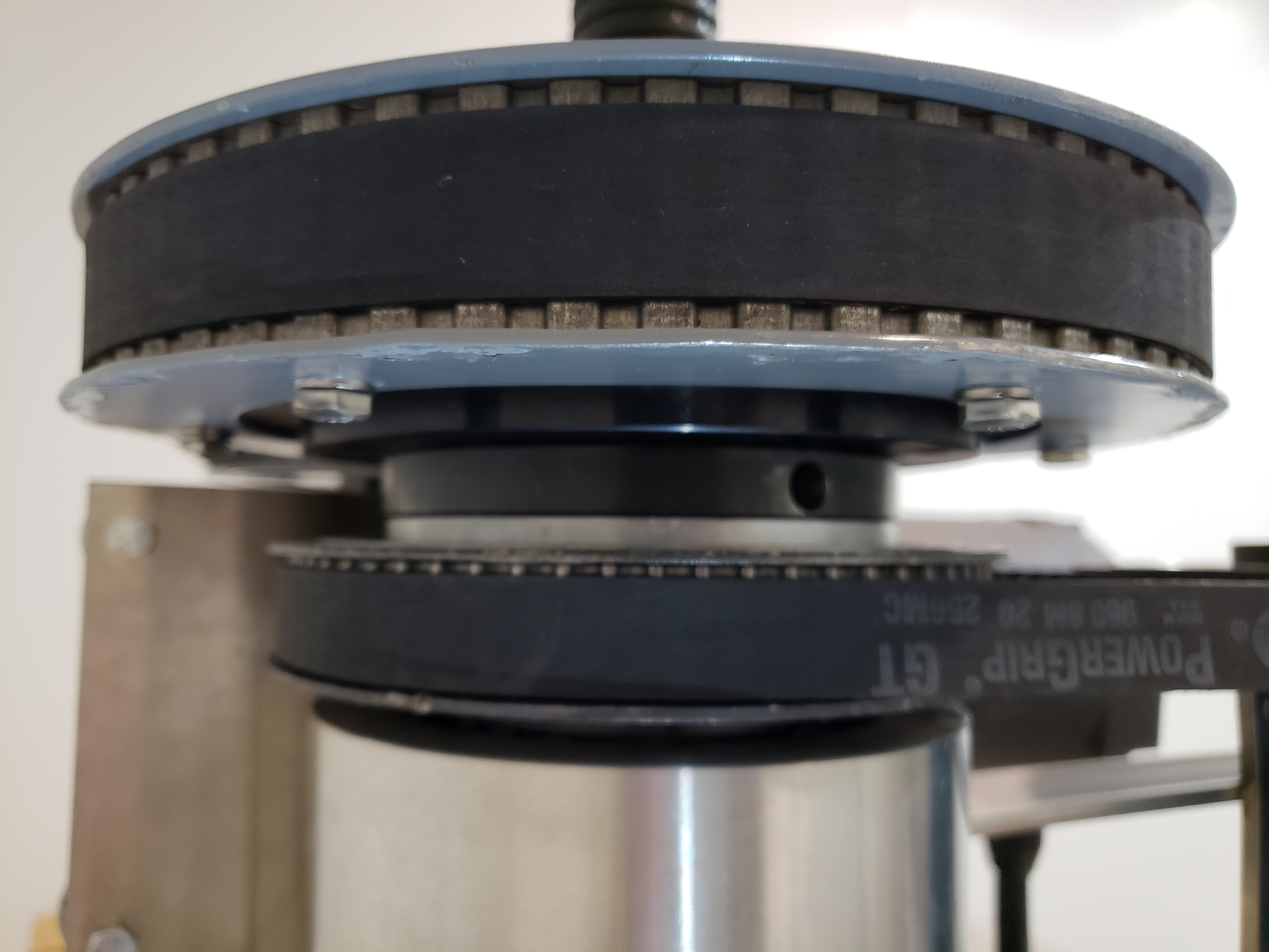
More inspections yesterday of H-GV4 to verify spacer exists and status of belts. The set screws are not visible from the peep hole, and we have no plans to drive the ball nut on this particular valve to inspect the set screws.

Images attached to this comment
Displaying reports 43461-43480 of 88617.Go to page Start 2170 2171 2172 2173 2174 2175 2176 2177 2178 End