Displaying reports 43501-43520 of 88617.Go to page Start 2172 2173 2174 2175 2176 2177 2178 2179 2180 End
Reports until 08:10, Thursday 17 January 2019
H1 PSL (PSL)
peter.king@LIGO.ORG - posted 08:10, Thursday 17 January 2019 - last comment - 17:55, Thursday 24 January 2019(46498)
FSS measurements (continued)
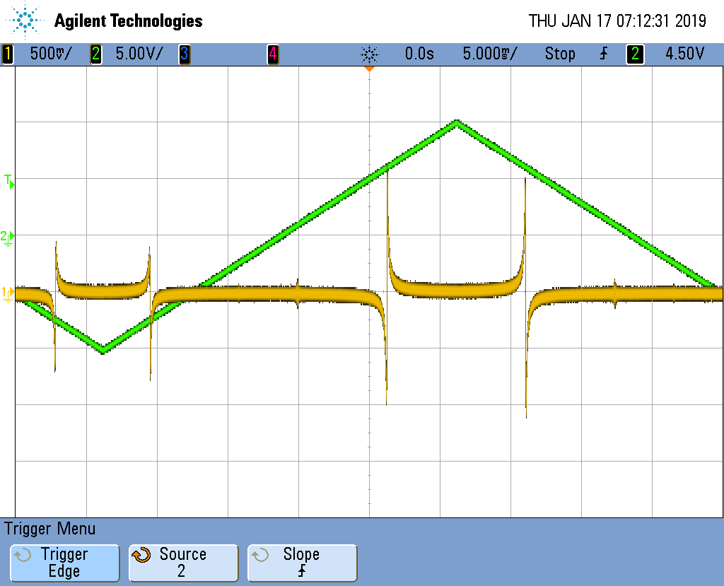
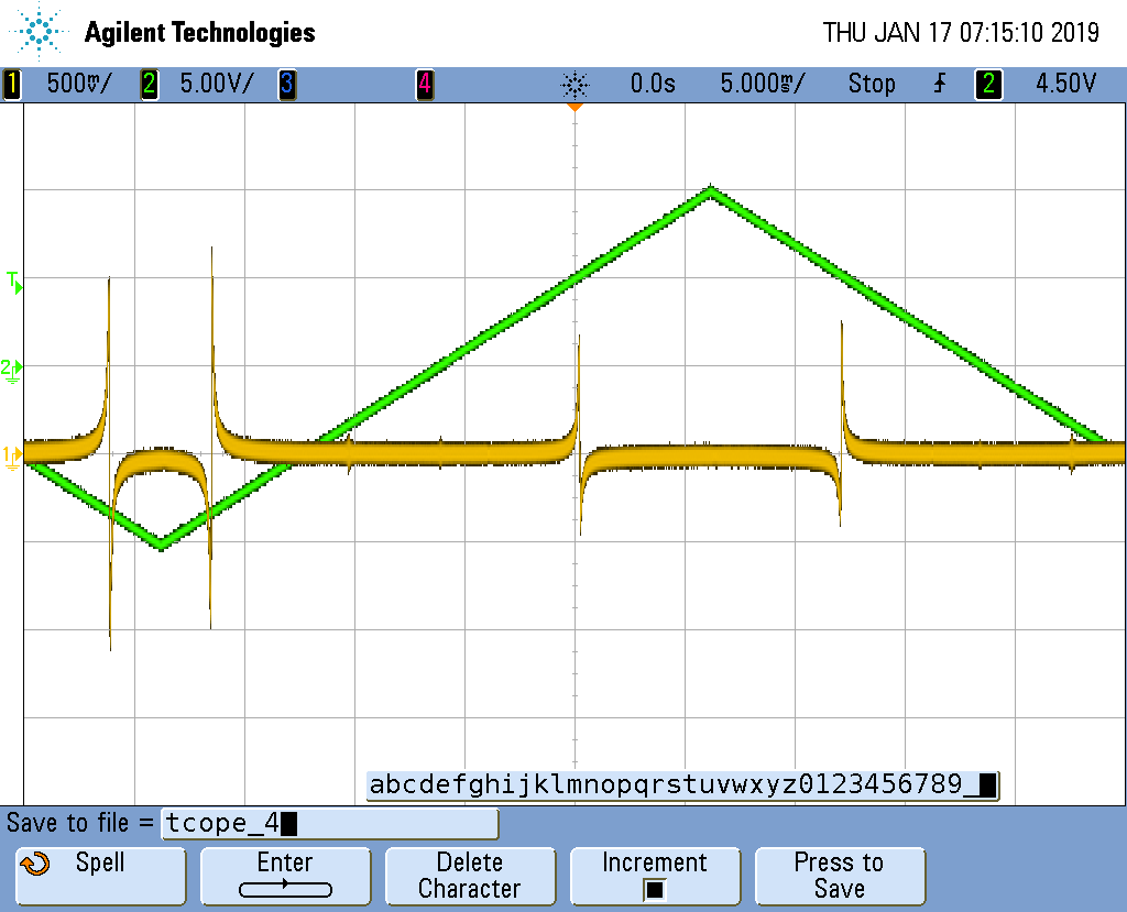
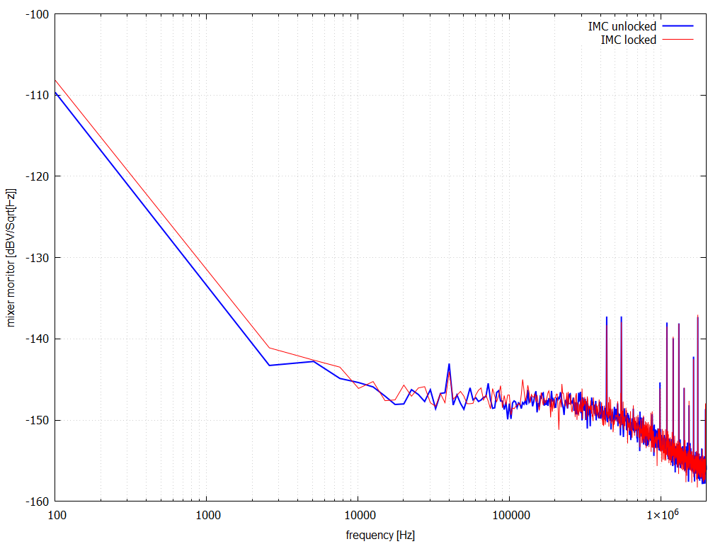
Following on from yesterday's attempt.  I made transfer function and spectra measurements with the input modecleaner locked and
unlocked.  In summary, there wasn't too much difference in the noise spectra above 100 kHz with the input modecleaner locked
or unlocked.

    Attached are transfer function measurements when the input mocdecleaner was unlocked and locked respectively (IMCULKD1.tif,
IMCLKD1.tif).  The noise spectra measurements are IMCULN1.tif and IMCLN1.tif respectively.  The mixer calibration was measured
to be 1.93/77.4 V/kHz.

    More to follow ...
Images attached to this report
Comments related to this report
peter.king@LIGO.ORG - 11:44, Thursday 17 January 2019 (46503)
mxr_imc.txt: FSS mixer monitor signal from 100 Hz to 2 MHz, measurement taken with 4395A and active probe
             plotted as hfmxr.png

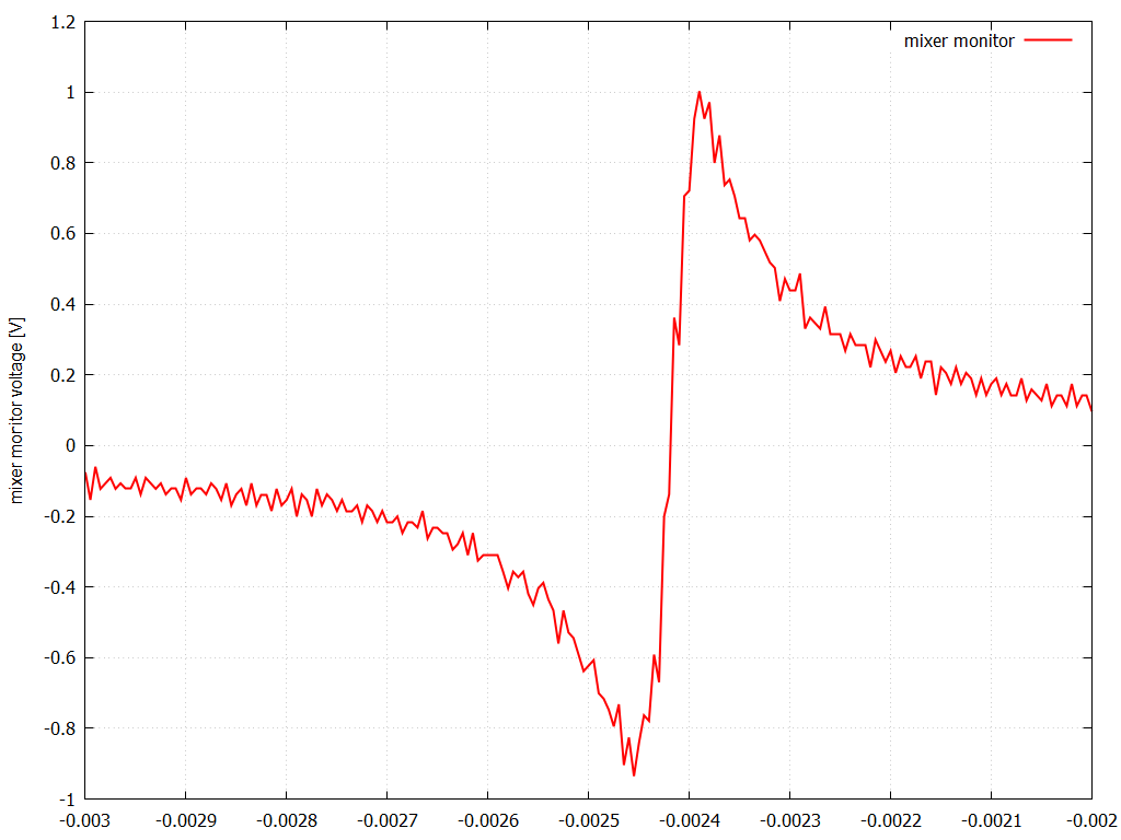
c1.txt: mixer monitor signal at the carrier, zoomed in
        plotted as carrier.png

MXR[1-4].txt and MXRIMCL[1-4].txt: FSS mixer monitor signal from 10 Hz to 100 kHz, measurement taken on
                                   SR7855, plotted as mxr.png
Images attached to this comment
Non-image files attached to this comment
craig.cahillane@LIGO.ORG - 17:55, Thursday 24 January 2019 (46631)
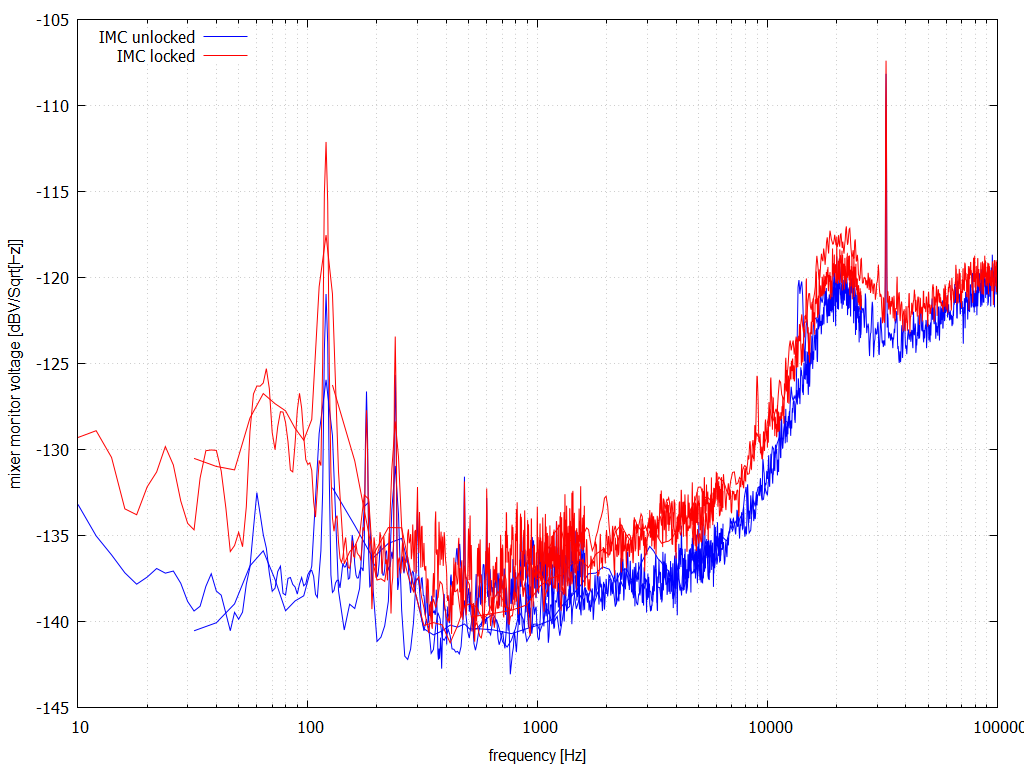
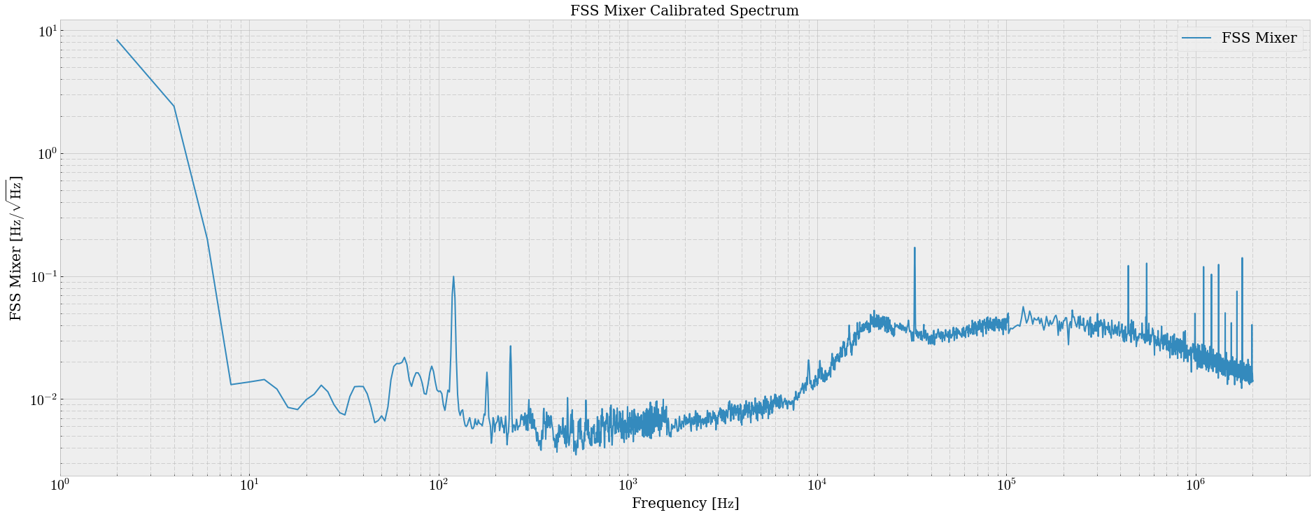
I stitched and calibrated Peter's FSS mixer data with IMC locked from the SR785 and Agilent together, multiplying the Agilent spectrum by a factor of 25 to get them to match up.
Images attached to this comment
H1 ISC (ISC)
craig.cahillane@LIGO.ORG - posted 04:35, Thursday 17 January 2019 - last comment - 11:37, Friday 18 January 2019(46495)
Locking tonight
Koji, Craig

- We ran the RF9 modulation depth change test Sheila asked us to do.  Koji will post an alog about those results.

- Koji had me lock the OMC with PZT2 at only 2 volts, rather than the usual ~40 V, for +9MHz 9th order HOM considerations.

- We measured the PRCL OLG after full thermalization at high power, and got a 30 Hz UGF.  This seems much lower than what was reported by Jenne a week ago.

- I carried the laptop in with me as I made my way down to the PSL racks.  
This time, I was able to make it without causing a lockloss, but when I got there the SR785 GPIB was gone, and when going to get it from the squeezer bay, while walking between HAM2 and HAM3 I killed the lock.
The area directly in front of the door in the LVEA, between HAM2 and HAM3, is the most sensitive to walking around, according to IMC_F.  Stepping on the lower tier floor directly inside of the LVEA door seemed to produce the largest response in IMC_F, including during my first excursion to the PSL racks.

- We reached nominal low noise again, but lost it within ten minutes, probably due to some CHARD, DHARD pitch ringup.  

- We reach NLN a third time, and this time held it for two hours, during which I was able to get to the PSL racks and measure all CARM spectra.  We eventually lost lock due to a super slowly growing ASC 0.9 Hz oscillation (lost lock about an hour after the ringup started).

- Had to readjust TMSY alignment in pitch significantly to get the guardian to continue locking in FIND_IR.
Comments related to this report
koji.arai@LIGO.ORG - 05:17, Thursday 17 January 2019 (46496)

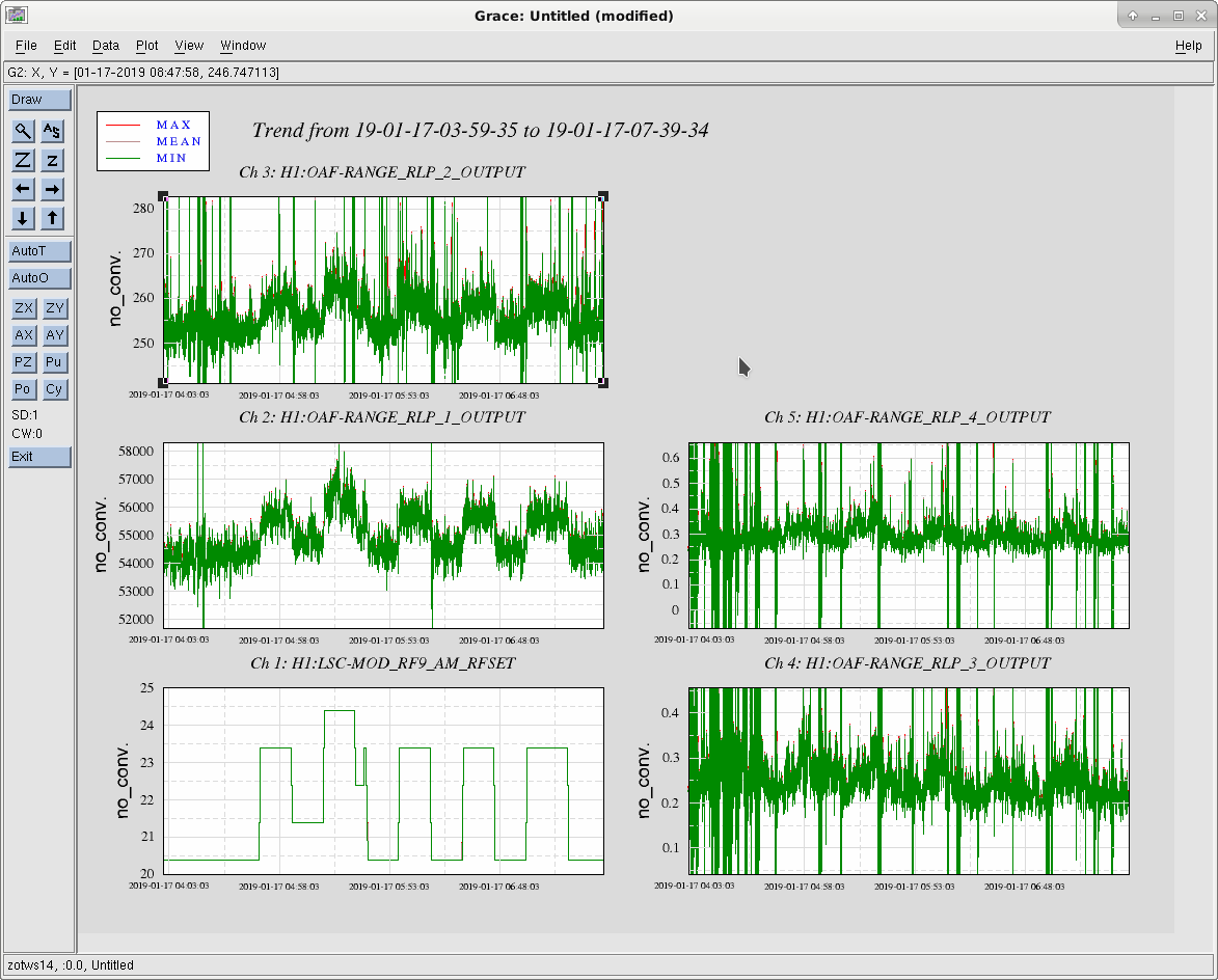
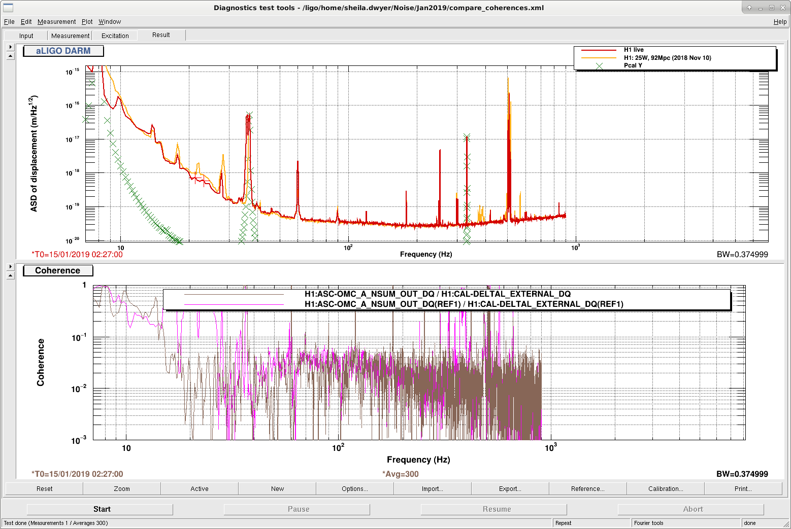
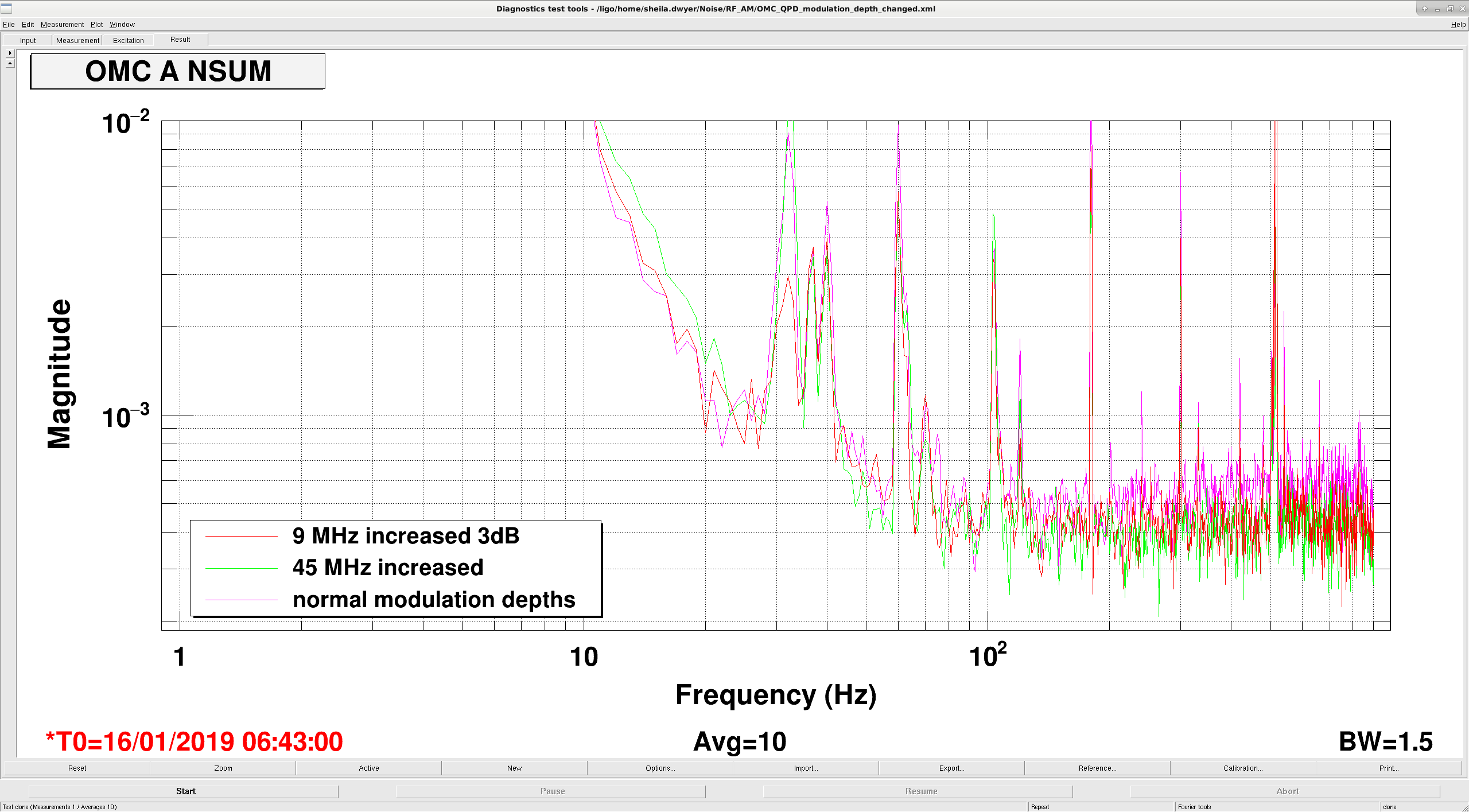
We started the modulation of the modulation depth from 4:48 UTC. I'd say the data from 5:43 UTC is clean. (Attachment 1 Left Bottom Plot). The modulation power for 9MHz was switched between 20.4dBm (LOW) and 23.4dBm (HIGH). We could clearly see that the DARM noise power in each monitored frequency band (Other plots in Attachment 1, RLP1: 10-20Hz, RLP2 20-29Hz, RLP3 38-60Hz, RLP4 60-100Hz, RLP5 100-450Hz). Interestingly, the change of the noise power is visible even at the lower frequency (10-20Hz) although the change is small (~4%) and difficult to confirm with the power spectrum.

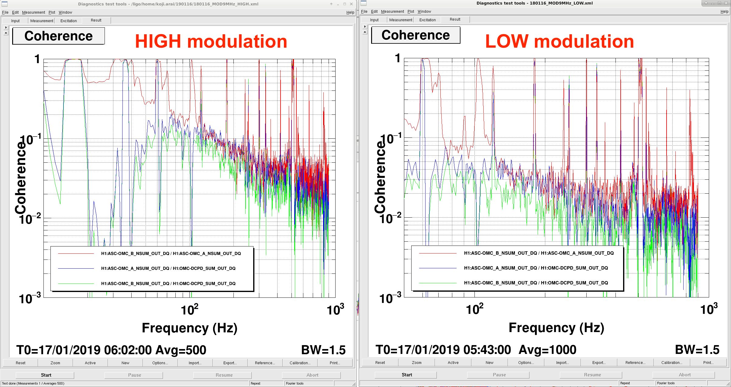
The coherence between DCPDSUM and OMC QPDs (as well as the coherence between the QPDs) were measured both in the HIGH and LOW states.

Attachment 2:
High modulation depth: 17/1/2019 6:02:00 UTC~ 1HzBW 500AVG
Low modulation depth: 17/1/2019 6:15:00 UTC~ 1HzBW 500AVG

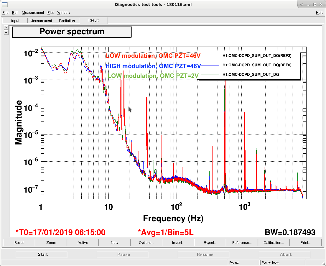
The comparison of the OMC DCPD spectra (=DARM) is shown in Attachment 3. Here we added another plot with the low modulation and OMC PZT Voltage around 0 (i.e. One FSR away from the nominal locking point). This gave us ~85Mpc, probably because of slightly better rejection of 9MHz SB by the OMC (not so certain).

We took the relatively glitch free data for the high modulation state between 17/1/2019 7:01:45UTC~7:13:45UTC.

Images attached to this comment
koji.arai@LIGO.ORG - 17:02, Thursday 17 January 2019 (46517)

As the OMC QPD signal contains the carrier TEM00 too, the coherence between DCPD and QPDs can not be completely zero. I have not yet estimated the quantitative limit what the minimum coherence we can realize by eliminating the 9MHz noise.

sheila.dwyer@LIGO.ORG - 11:37, Friday 18 January 2019 (46529)

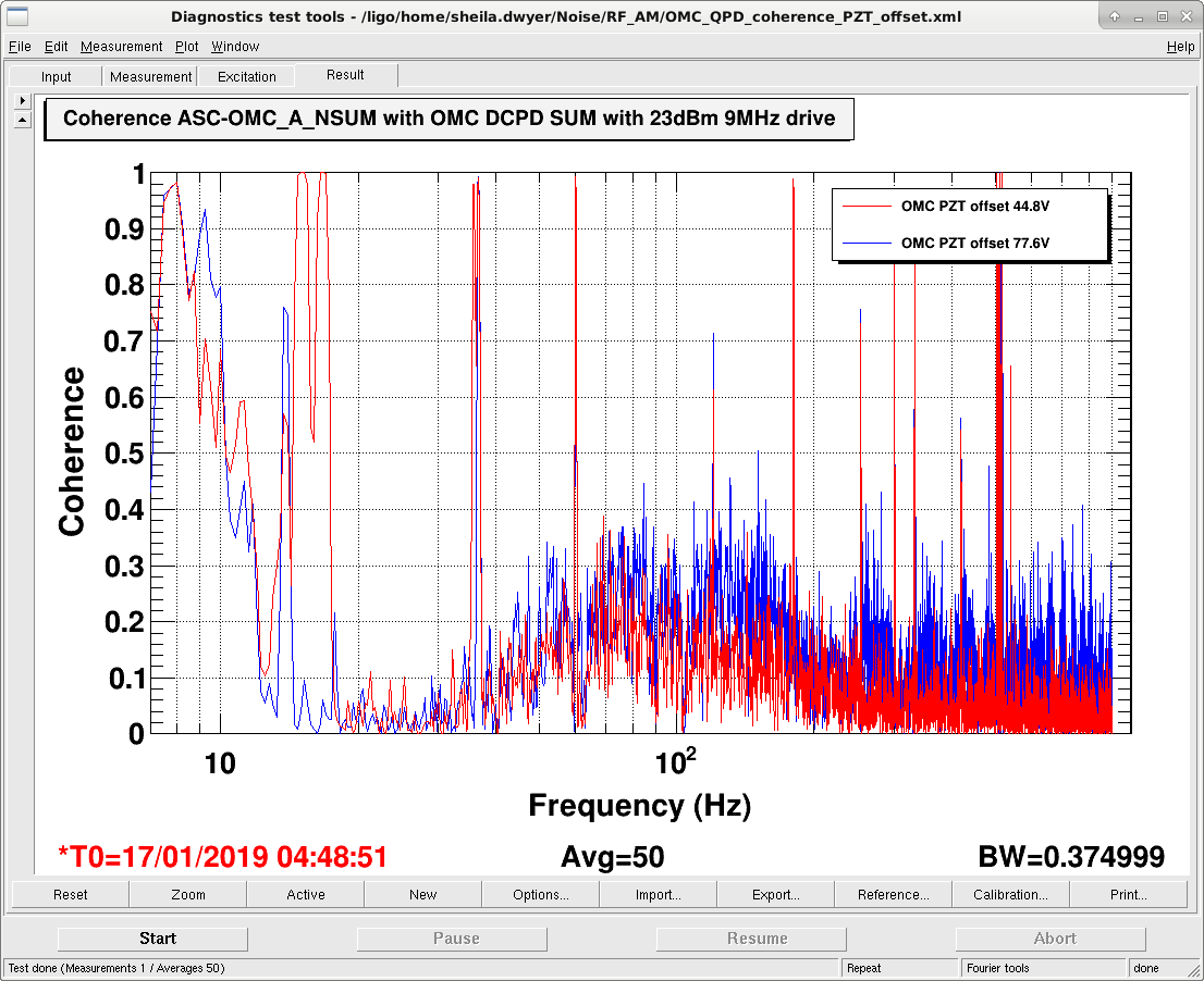
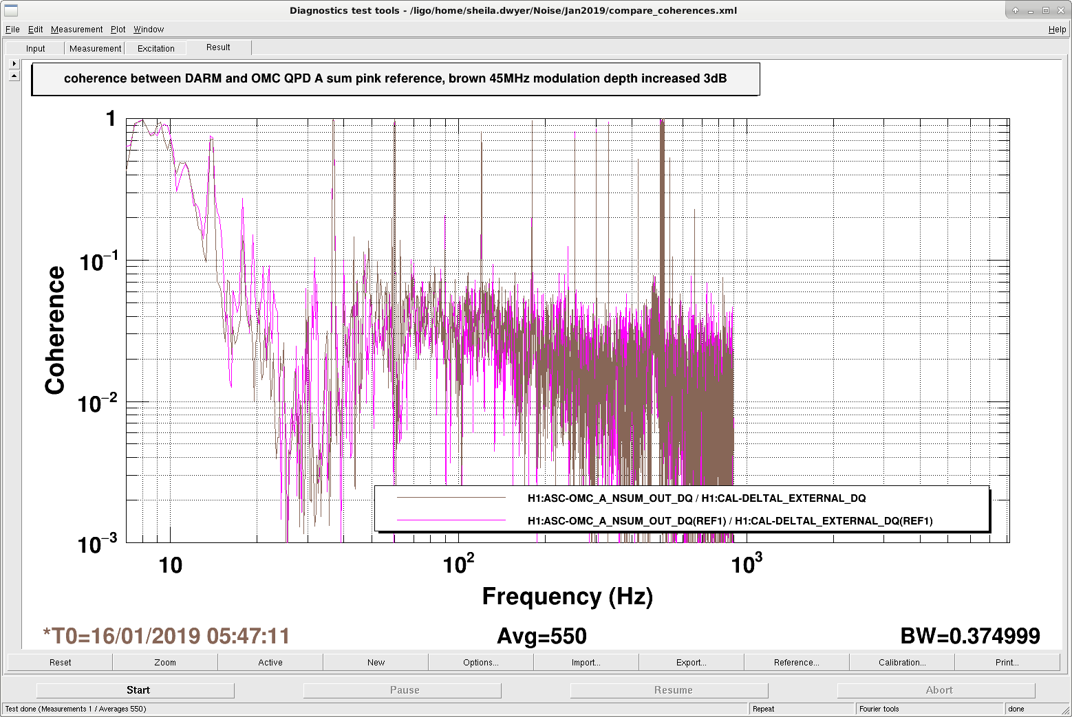
Here's a comparison of two times when the 9 MHz modulation depth was increased to have 23dBm at the driver, with different OMC PZT offsets. 

The first time is Jan 16th at 6:40:30 UTC, with an OMC PZT2 monitor readback of 77.6 V, the second time is Jan 17th at 4:48:51 UTC with PZT2 at 44.8 Volts. 

The coherence between the OMC QPD and the DCPD's is lower for the lower PZT voltage, which fits with Koji's model that the 9 MHz is reaching the DCPD's through the higher order mode which has an OMC resonance close to the carrier resonance.

Images attached to this comment
H1 PEM (DetChar)
robert.schofield@LIGO.ORG - posted 22:26, Wednesday 16 January 2019 (46494)
An easy optic damping system reduces remaining optic mount jitter peaks in DARM by more than 3

Figure 1 shows that yesterday the two jitter peaks in DARM were successfully damped and the peak amplitude reduced by a factor of 3 or more.

Recently I had identified the mounts that were responsible for the jitter peaks in DARM that remained after the reduction in table motion from the water cooling system (https://alog.ligo-wa.caltech.edu/aLOG/index.php?callRep=44460), suggesting a broad-band tuned mass damping system. Rick S. pointed out some leftover dampers that had been made for the PMC, based on OMC bench damping investigations (https://dcc.ligo.org/LIGO-T1600494). I recycled some of these parts and mounted them on the U200-A mounts that were creating peaks in DARM.

Figure 2 shows the system, the damper is bolted to the hole on the side of the U200-A that is used for mounting in the other orientation. The manufacturers hole is counterbored so the bolt head does not extend beyond the mount. The extra weight did not deflect the bottom periscope mirror enough to prevent OMC locking.

It took only a couple of minutes to install each, so I think this might be a useful system for all critical mounts in the future. We might make a smaller version for U100-As.

Cheryl also replaced one of the optics because she thought it might be damaged.

Robert, Cheryl

Non-image files attached to this report
H1 AOS (DetChar)
robert.schofield@LIGO.ORG - posted 22:05, Wednesday 16 January 2019 (46493)
High EY vibration coupling

Tonight we were able to shake at EY after finishing EX last night. We found the EY vacuum enclosure to couple much more to DARM than the EX enclosure, and more than during O2. The Figure shows that factors of 10 increase in motion (which happens between 4 and 12 Hz when big trucks pass on 240), produce large scattering features in DARM. More later.

Robert, Kara

Non-image files attached to this report
H1 INJ (INJ)
keith.riles@LIGO.ORG - posted 20:25, Wednesday 16 January 2019 - last comment - 05:28, Thursday 17 January 2019(46492)
Moved CW injections to new Guardian-controlled excitation
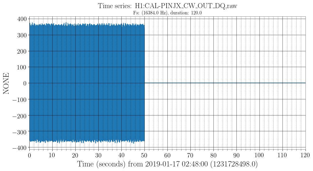
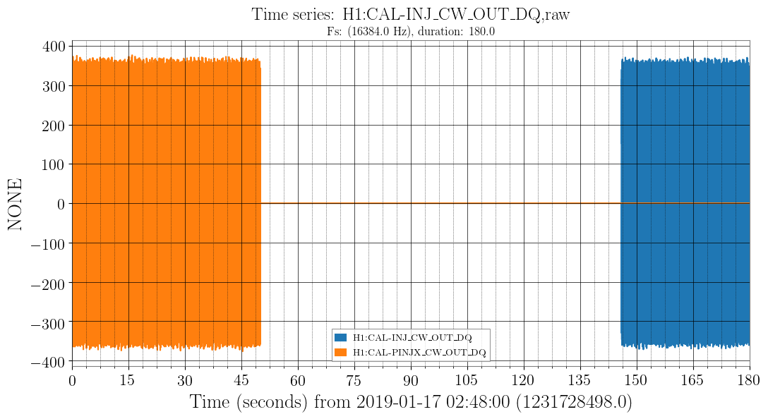
I turned off CW injections from the old injection channel H1:CAL-PINJX_CW_EXC at GPS 1231728548 (Jan 17 2019 02:48:50 UTC) and restarted them using the new injection channel H1:CAL-INJ_CW_EXC at GPS 1231728644 (Jan 17 2019 02:50:26 UTC).

I am not currently able to verify using ldvw / nds2 that the injections are appearing, but Keita confirmed via e-mail he can see them being routed to h1calex.

The screenshot shows the injections turning off in CAL-PINJX, but I can't yet show them turning on in CAL-INJ
Images attached to this report
Comments related to this report
keith.riles@LIGO.ORG - 05:28, Thursday 17 January 2019 (46497)
nds2 now sees the CAL-INJ channels. The attached figures shows the turnoff in CAL-PINJX_CW_OUT followed by the turnon in CAL-INJ_CW_OUT
Images attached to this comment

H1 SQZ (SQZ)
nutsinee.kijbunchoo@LIGO.ORG - posted 18:17, Wednesday 16 January 2019 - last comment - 14:53, Friday 18 January 2019(46489)
Comparing the NLG using two different methods

We are still trying to nail down our non-linear gain measurement. Here's a comparison between two methods:

1) MIT method:

nlg = ((sqrt(pMax/pMin) + 1)/2)^2

2) ANU method:

nlg = pMax/pUnamp

pUnamp is seed transmission measured outside nlg region as I scan the OPO cavity (temperature set to ~51C, green blocked). Which is an unamplified seed power.

I took nlg measurement with data from StripTool and oscilloscope. The result are consistent within 10% between the two methods and two devices. 


Pump input to coupler: 20mW

Pump reflected (OPO off resonance): 2.7 mW

Seed input to coupler: 1 mW


StripTool (IR trans PD): max = 0.0063 mW, min = 0.0019 mW, DN = -6.8e-5 mW

Scope (IR trans PD): max = 142 mV, min = 47.6mV, DN 8mV

Seed trans unamplified: StripTool = 0.003 mW, Scope = 76.4 mV


  StripTool Oscilloscope
MIT Method 1.958 2.015
ANU Method 2.1 1.85


Comments related to this report
nutsinee.kijbunchoo@LIGO.ORG - 14:53, Friday 18 January 2019 (46532)

Note that 20dB attenuator is off during this measurement.

H1 ISC
jenne.driggers@LIGO.ORG - posted 18:07, Wednesday 16 January 2019 (46488)
Trouble with reduce 9MHz reduction state

We lost lock while going through the 9MHz reduction state.  This might be the second time today, although the first time I thought it was due to the extra 6dB of gain in the CARM loop. 

Perhaps part of the problem is that the PD digital gains (which get increased to compensate for the actual modulation depth reduction) are ramped over 30 sec, while the analog EOM driver is just making 3 discrete steps over 6 seconds.  We need to look into this.

However, while looking at the state REDUCE_RF9MHZ_MODULATION_DEPTH, I saw that the ASC 45 MHz photodiodes were getting their digital gains increased by 3dB.  Ooops.  I have fixed this, however we'll need to pay attention to the ASC loops, that in NomLowNoise they'll now have 3dB less gain then they were having.  Should be okay, since all the loops are stable and were set before the modulation depth reduction.

H1 ISC (ISC)
craig.cahillane@LIGO.ORG - posted 17:46, Wednesday 16 January 2019 - last comment - 16:44, Monday 05 August 2019(46483)
IMC REFL and REFL A/B shot and dark noise levels
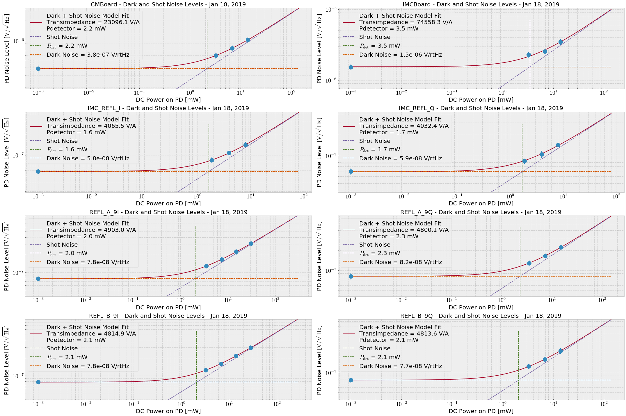
On Monday evening, Koji and I went out and measured the shot and dark noise of the IMC/CARM PDs.  Then, Koji taught me how to think about photodiode noise.  Slides 35 and 36 of G1401145

Model:

where nV is the voltage noise floor, T is the transimpedance, e is the electron charge, R is the responsivity of e λ/(h c) = 0.858 A/W, QE is the quantum efficiency of 0.9, PDC is the DC power from the incident light, and Pdet is the power apparent from the intrinsic detector noise (i.e. the incident power where shot and dark noise are equivalent).

We fit the measured shot and dark noise spectra for IMC REFL I/Q, REFL_A 9I/Q, REFL_B 9I/Q, and at the CARM and IMC servo board OUT2 locations with the nominal gain slider settings (OUT2 connected to IN1, CMB IN1GAIN = 6 dB, IMC Board IN1Gain = 28 dB).  REFL_A spectra are plotted in attachment 3 as an example.
For dark noise I shuttered the PSL.  For shot noise I measured with 1W, 2W, and 4W input requested power, and recorded how much light was reported by the LF channels:

Light Level      REFL_A_LF [mW]     REFL_B_LF [mW]    IMC_REFL_LF [mW]
----------------------------------------------------------------------
Dark                          0                  0                   0
1W PSL                     3.51               3.24                1.87
2W PSL                     7.38               6.80                3.92
4W PSL                    15.08              13.90                8.01

Full Lock                  4.36               4.02                1.15


Then, I found the average noise floors for each spectrum between 3 and 10 kHz, and fit the model to the data.  (attachment two)
I have let the transimpedance number from the fits capture the servo board gain sliders.

Photodiode      Transimpedance [V/A]     Pdet [mW]    IN1 Gain Slider [dB]
-------------------------------------------------------------------------------------
CMBoard                        730.4          2.2                       6
IMCBoard                      2357.7          3.5                      28
IMC_REFL_I                     128.6          1.6
IMC_REFL_Q                     127.5          1.7
REFL_A_9I                      154.9          2.0
REFL_A_9Q                      151.8          2.3
REFL_B_9I                      152.4          2.1
REFL_B_9Q                      152.2          2.1

Images attached to this report
Comments related to this report
craig.cahillane@LIGO.ORG - 19:02, Sunday 20 January 2019 (46552)
The transimpedance numbers above are incorrect.  In the model I did not convert mW to W for the calculation, so all numbers were scaled down.
Posted is a corrected plot.

Images attached to this comment
craig.cahillane@LIGO.ORG - 16:44, Monday 05 August 2019 (51038)
Comments from Daniel

"... the transimpedance typically describes the electronics gain. However,
yours doesn't. The shot noise eq is missing a sqrt(2), and the demod will fold noise 
below the LO and above the LO on top of each other, which results in another sqrt(2).

So, your T is twice as large as the electroncis gain. For IMC REFL the mesured RF gain
of the PD is 353 Ohm, the demod gain is ~5.4 which gives 1.9k."

Essentially, the above model ignores a overall factor of 2, and collects the demod gain of 5.4 into the transimpedance, which is not correct.

So, for IMC_REFL_I above, the transimpedance is actually 4065 / 5.4 / 2 = 376 ohms, close to the direct measured 353 ohms Daniel reports.
REFL_A_I transimpedance: 4903 / 5.4 / 2 = 454 ohm
REFL_B_I transimpedance: 4814 / 5.4 / 2 = 446 ohm
H1 General (DetChar)
laura.nuttall@LIGO.ORG - posted 17:40, Wednesday 16 January 2019 (46484)
More whistle investigations

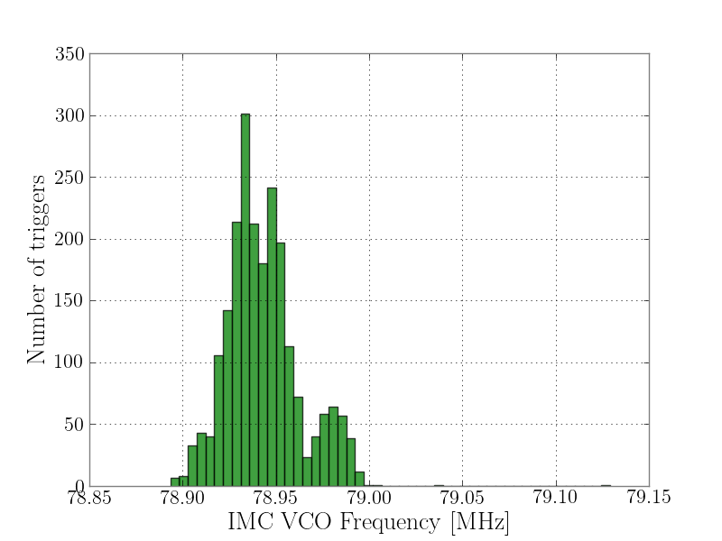
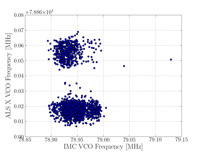
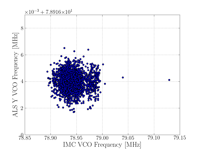
Whistles have been appearing in the top two rounds of hveto for the last 3 days. To get some better statistics about the troublesome frequencies the IMC VCO is crossing when whistles are produced, I grabbed the times of all the glitches hveto finds in the top 2 rounds. Note, not all the glitches in these rounds will be whistles, but the majority will be. I then looked at the IMC VCO frequency when these glitches were present and plotted a histogram (Figure 1). Whistles appear most often ~78.94MHz. 

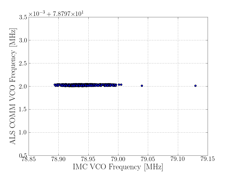
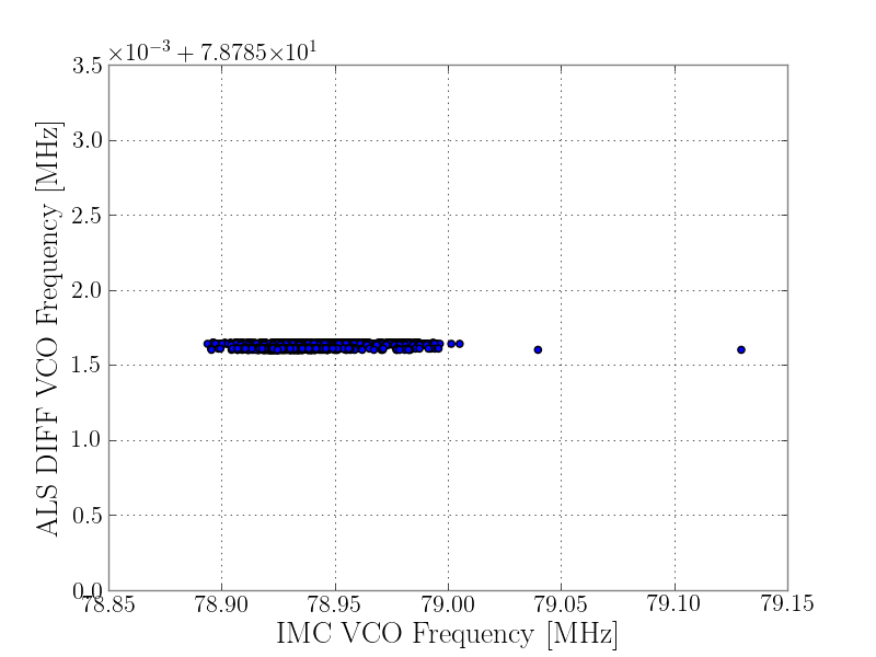
I then started to look at other VCOs (regardless of where they are) just to see what their frequencies were when whistles appeared. I grabbed ALS COMM, ALS DIFF, ALS X, ALS Y and SQZ. I then made scatter plots of the different VCO frequencies against the IMC VCO frequency when whistles were present (ALS COMM - Figure 2, ALS DIFF - Figure 3, ALS X - Figure 4, ALS Y - Figure 5, SQZ - Figure 6, apologies for the odd rendering of the y axes). It looks like ALS COMM and ALS DIFF are happily parked away from the troublesome IMC VCO frequencies. The SQZ VCO also wanders away from the IMC VCO frequency range around 79.168MHz. Even though ALS X and ALS Y are many km away from the IMC VCO I still looked at them just in case it was interesting. These VCOs do wander the closest to the IMC VCO. 

Images attached to this report
H1 ISC
daniel.sigg@LIGO.ORG - posted 16:37, Wednesday 16 January 2019 - last comment - 12:44, Thursday 17 January 2019(46482)
QPD calibration

Added a few filter modules to the ASC-OMC_A and ASC-OMC_B QPD segments to account for the calibration:

Comments related to this report
daniel.sigg@LIGO.ORG - 12:44, Thursday 17 January 2019 (46509)

WFS DC Calibration

Added new filter modules to the ASC-AS_A/B, ASC-REFL_A/B and ASC-POP_X WFS DC segments to account for the calibration:

  • FM5: "–20dB" is the inverse of the whitening gain that can be selected on the front panel of the WFS Interface chassis
  • FM6: "cts2V" calibrates counts into Volts 6.1035E-4
  • FM7: "trans" goes from Volts to Amps and is the inverse of the transimpedance gain. The later is 1000Ω including the differential amplifier.
  • FM8: "A2W" goes from Amps to Watts.
    • For an InGaAs diode at 1064nm this is 1/0.8 = 1.25 (used).
    • For a silicon diode at 532nm this is 1/0.3 =3.333.
    • For a silicon diode at 1064nm this is 1/0.16 = 6.25.
  • FM9: "milli" goes to mW (multiplies by 1000)

The front panel gains are set to high (+20dB) for the AS WFS, and low (0dB) for the others.

H1 General
cheryl.vorvick@LIGO.ORG - posted 15:59, Wednesday 16 January 2019 (46481)
OPS Day Summary:

TITLE: 01/16 Day Shift: 16:00-00:00 UTC (08:00-16:00 PST), all times posted in UTC
STATE of H1: Commissioning
INCOMING OPERATOR: None
SHIFT SUMMARY:  new Guardian hardware installed the morning, useism increasing
LOG:


H1 DAQ (DAQ)
stefan.countryman@LIGO.ORG - posted 14:41, Wednesday 16 January 2019 (46477)
Checked Timing Comparator 1PPS input ports to document which devices connect where

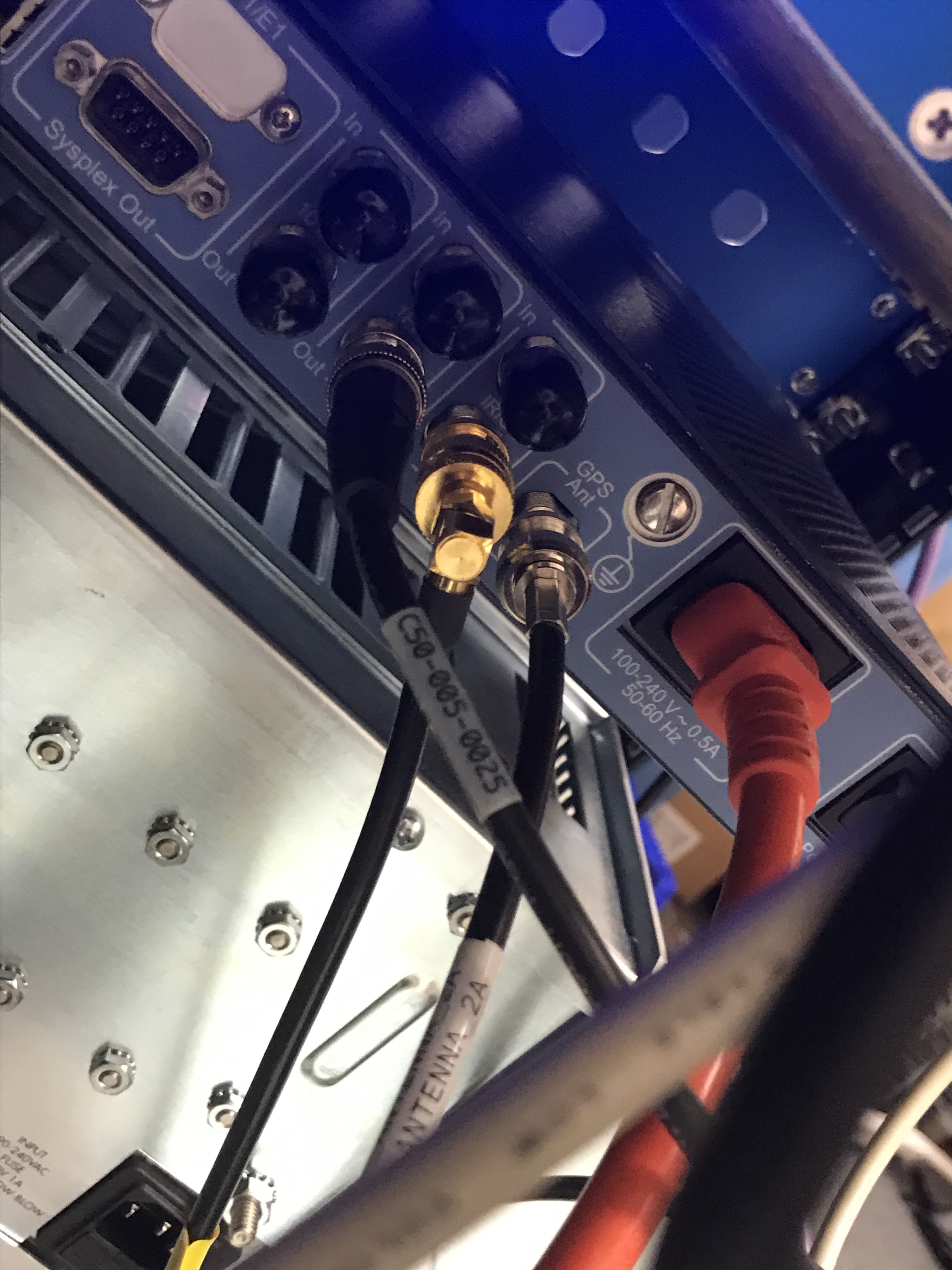
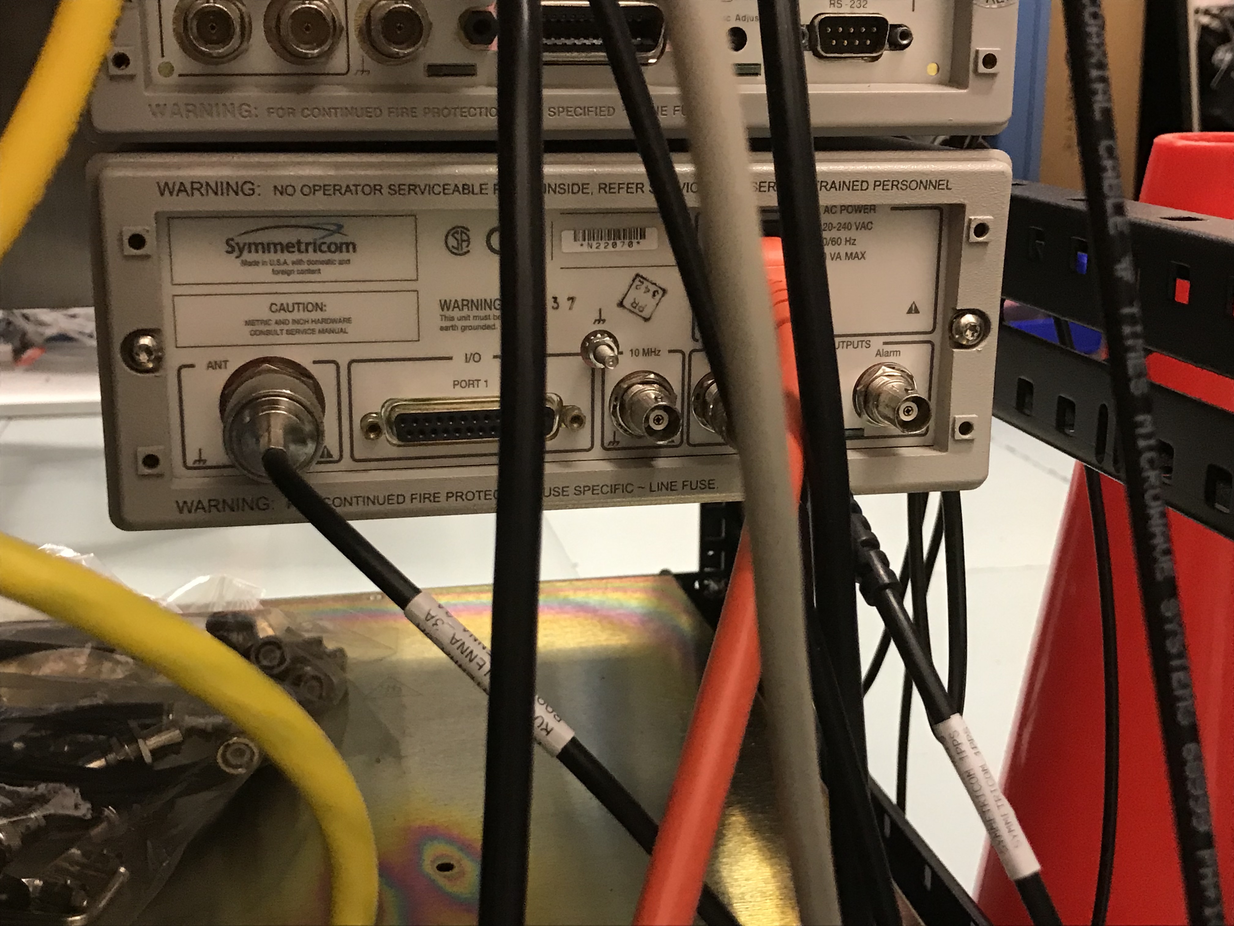
Yasmeen, Ana, Stefan

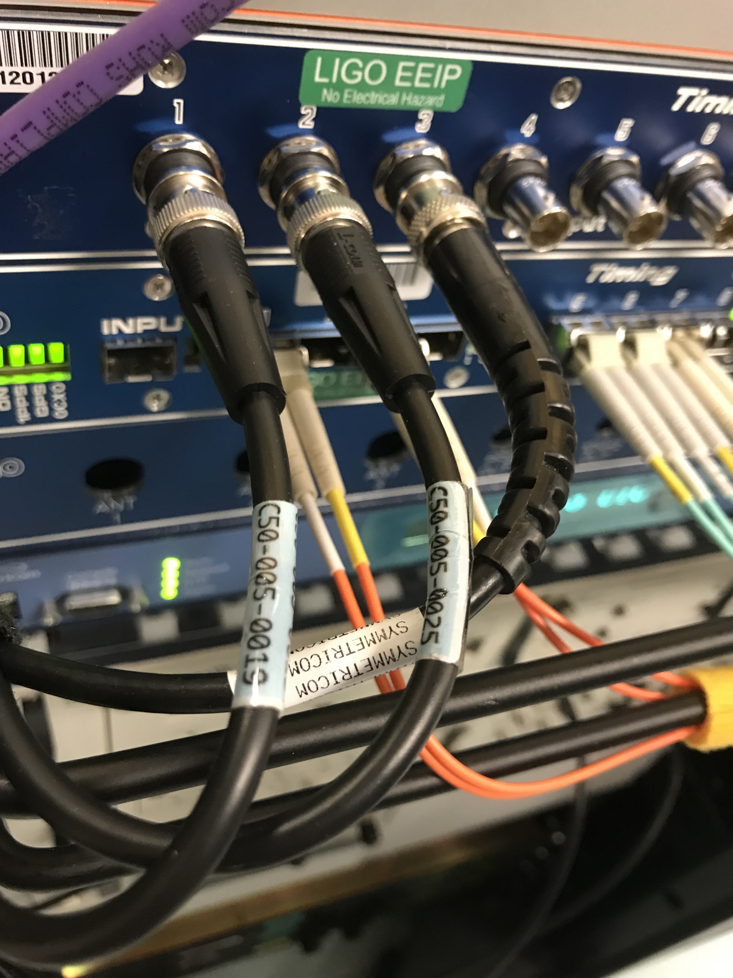
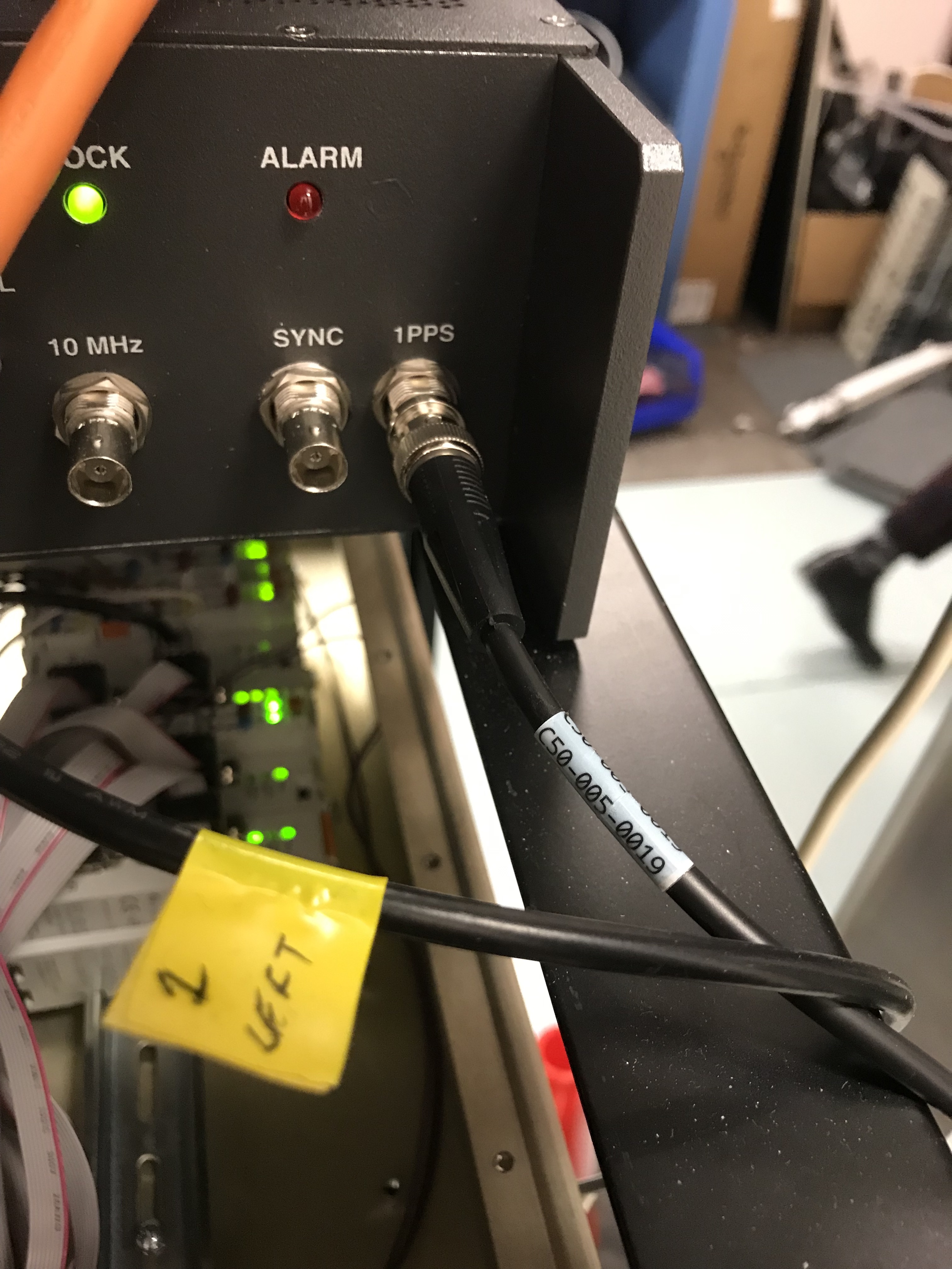
Went into MSR at 1:30pm local to visually check which 1PPS cables feed into which Timing Comparator 1PPS input Port. No changes were made. Photos taken and attached.

Cable Description Cable Name Comparator [1-7]
Cs-III Cesium Atomic Clock 1PPS Out C50-005-0019 1
S350 Network Time Server 1PPS Out C50-005-0025 2
Symmetricom 58503B GPS 1PPS Out SYMMETRICOM_1PPS 3


Images attached to this report
H1 ISC
sheila.dwyer@LIGO.ORG - posted 23:18, Tuesday 15 January 2019 - last comment - 17:32, Wednesday 16 January 2019(46459)
ASC slow instabilities much better, changes not in guardian

Sheila, TVo, Georgia, Craig, Danny

This current ASC situation seems better than what we've had the last several days, so we probably want to make some of these changes permanent, but we don't want to make any changes in the guardian since ASC engagement has been tricky and we may not have a chance to test things. I think that turning off PRC1Y, and increasing the CHARDY gain from 3 to 6 are definitely improvements.  The change to the CSOFT input matrix I'm not so sure about. 

Comments related to this report
jenne.driggers@LIGO.ORG - 17:32, Wednesday 16 January 2019 (46486)

I've put the CHARD_Y gain increase and the PRC1_Y loop-off at the end of ENGAGE_SOFT_LOOPS.  I have not changed the SOFT input matrix.

In addition, since we haven't been using the DSOFT_P loop lately, I've told the guardian to stop turning on the DSOFT_P radiation pressure compensation.  Now, when guardian is turning on the RPC stuff, if the DSOFT_P gain is zero, then it skips over DSOFT.

H1 ISC
sheila.dwyer@LIGO.ORG - posted 23:13, Tuesday 15 January 2019 - last comment - 19:25, Wednesday 16 January 2019(46444)
9MHz sideband causing DARM noise, clues for 90 Hz peak

Summary: BRUCO gave us a few interesting clues about our current noise, including a broadband contribution to the DARM noise that seems to couple through the 9 MHz sideband. 

We had 20 minutes of glitch free data from 1231532246 to 1231533411.  This was before Georgia and Danny fixed the ISS second loop clipping 46412, which improved the noise from 27-15 Hz and around 350-400 Hz. Gabriele and Joe Areda managed to run BRUCO (and update the code to deal with some other updates), a report is here: https://ldas-jobs.ligo.caltech.edu/~gabriele.vajente/bruco_lho_1231532246/

Some interesting features (other than the ISS coherence)

Images attached to this report
Comments related to this report
jenne.driggers@LIGO.ORG - 11:11, Wednesday 16 January 2019 (46467)

Sheila just engaged a second stage of whitening for the OMC QPDs, so hopefully that will address the coherence there.  We can't just add DC gain, at least until the 45 MHz modulation depth is reduced, otherwise we'll saturate the diodes.

sheila.dwyer@LIGO.ORG - 19:25, Wednesday 16 January 2019 (46490)

Our nominal powers on the EOM driver right now are 20dBm for 9 MHz, and 23.6 dBm for the 45 MHz.  (Those were the driver powers before we started changing things last night). 

By looking at the DC power on the OMC QPDs while we were changing the modulation depths last night we can find the relative powers in (carrier+118), 9 MHz and 45 MHz.  

  carrier 45 MHz power 9 MHz power
OMC QPD A 23% 67% 9.7%
OMC QPD B 19% 74% 7.4%

The attached spectrum comparison shows that the noise on the OMC QPD didn't increase in when the 9 MHz modulation depth was increased.  This means that the 9MHz amplitude noise is not the dominant noise in the OMC QPD, so we can't make that assumption to make a projection of the 9MHz amplitude noise into DARM. 

Images attached to this comment
H1 CAL (CAL, INJ)
jameson.rollins@LIGO.ORG - posted 15:19, Tuesday 15 January 2019 - last comment - 09:24, Saturday 19 January 2019(46407)
new hardware injection front end model installed: h1calinj

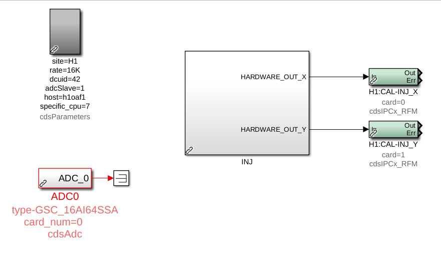
A new h1calinj model has been installed on the h1oaf1 machine.  This model will hold all front-end injection handling logic, including the injection EXC test points, under the channel prefix "H1:CAL-INJ_".  The existing injection handling code in the h1calex model ("H1:CAL-PINJX_") has been left as is for now to facilitate transitioning and testing.

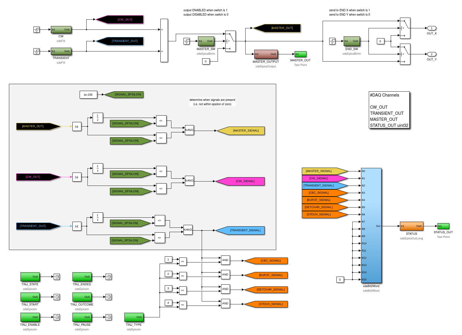
The first two attached images are of the top-level contents of the new h1calinj model, and of the contents of the "INJ" CAL_INJ_MASTER2 library part that contains all the core logic.  The top of the latter shows the main injection signal flow.  The two "CW" and "TRANSIENT" filter banks at the upper left hold the EXC inputs and calibration filters for the continuous-wave (CW) and transient (TRANSIENT) injection inputs respectively.  The outputs of the two modules are summed and the overall "MASTER" output goes through an output switch ("MASTER_SW"), and then finally a switch ("END_SW") that determines which of calex or caley receives the injection signal ("H1:CAL-INJ_{X,Y}" via cdsIPCxRFM).  Below the main signal path is logic to determine the presence of signals at various points in the injection path, and bundle that info into a single status word ("STATUS_OUT").

IPC receivers for the INJ_MASTER output sent from h1calinj (H1:CAL-INJ_{X,Y}) were added to the h1calex and h1caley models.  EPICS and acquired test point monitors of the received signals were also added.

NOTE: a single 2**14 Hz, 61 us cycle delay will be added to the injection path because of the IPC needed to carry the signal from the vertex to the ends.

The new acquired fast channels are:

The STATUS channels (the H1:CAL-INJ_STATUS_OUT_DQ uint32 fast channel and the H1:CAL_INJ_STATUS slow channel) have the following bits:

  1. MASTER
  2. CW
  3. TRANSIENT
  4. CBC
  5. BURST
  6. DETCHAR
  7. STOCH

A value of zero (0) indicates no signal of the specified type is present, and a value of one (1) indicates the presence of the specified signal.

The h1calinj model also holds the "TINJ" EPICS status bits, nominally set by the INJ_TRANS guardian node.  NOTE: the "H1:CAL-INJ_TINJ_" EPICS records were previously hosted by the ext_alert_ioc.py soft IOC running on the h1fescript0 machine.  The records were removed from the soft IOC and the process was restarted.

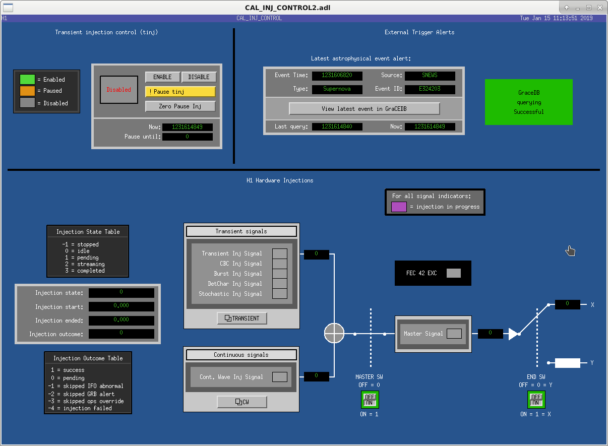
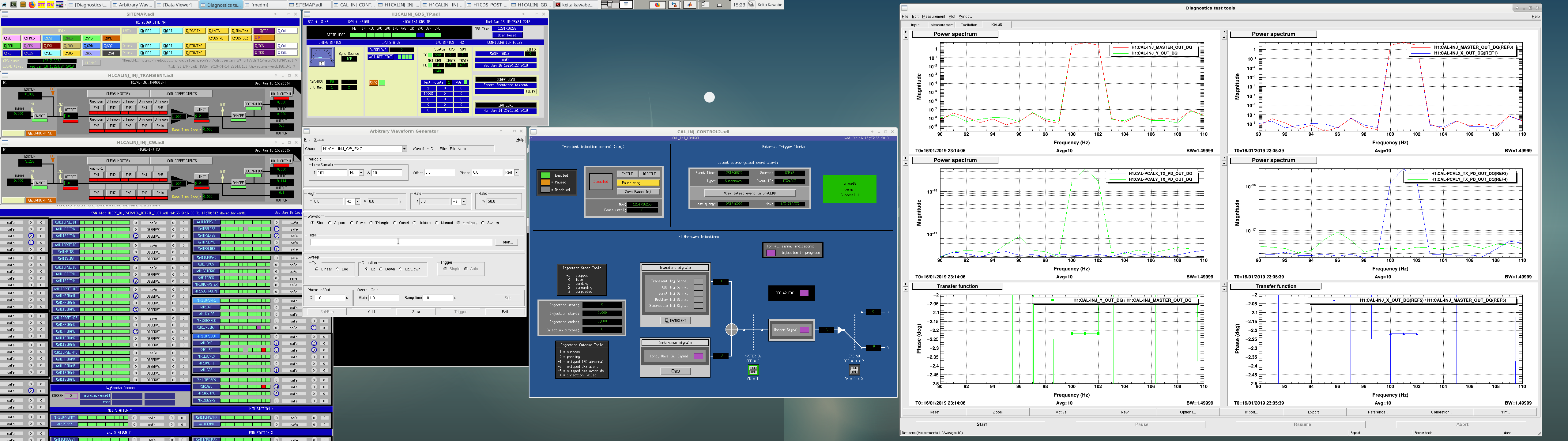
The final image attached is a new MEDM screen CAL_INJ_CONTROL2.   All functionality and status bits in the h1calinj model, and the monitors in h1calex and h1caley, are exposed.

As mentioned above, all the existing INJ infrastructure remains in place.  We leave it up to the INJ group to update the INJ_TRANS guardian, the psinject process, downstream monitors, etc.  We would like to schedule the removal of the old INJ infrastructure as soon as possible,

Images attached to this report
Comments related to this report
keita.kawabe@LIGO.ORG - 15:46, Wednesday 16 January 2019 (46480)

New MEDM screen is now accessible from the sitemap (cal-> hwinj ctrl). Old one is still there as "hwinj ctrl old".

I briefly tested the new frontend.

  • TRANSIENT INJ Signal bit of H1:CAL-INJ_STATUS responded correctly to excitation as well as an offset in H1:CAL-INJ_TRANSIENT filter module.
  • CW INJ Signal bit of H1:CAL-INJ_STATUS responded correctly to excitation as well as an offset in H1:CAL-INJ_CW filter module.
  • MASTER Signal bit of H1:CAL-INJ_STATUS responded correctly to excitation as well as an offset in either INJ_TRANSIENT or INJ_CW filter module.
  • Excitation bit of H1:FEC-42_STATE_WORD only responded to excitations but not offsets (of course).
  • H1:CAL-INJ_END_SW=1 or 0 correctly delivered the MASTER_OUT signal to h1calex or h1caley model (monitor points are H1:CAL-INJ_X_OUT and H1:CAL-INJ_Y_OUT).
  • Time delay from MASTER_OUT to h1calex and h1caley was  61.035us, which is almost exactly 1/(2^14Hz). This was measured by injecting sine wave at 101Hz to CW and measuring the transfer function from MASTER_OUT to X_OUT or Y_OUT.
  • H1:CAL-INJ_X_OUT or Y actually does go to PCAL laser power (done by looking at H1:CAL-PCALX_TX_PD_OUT or Y).

No surprise in the above. See the screen shot.

One surprise was that I had some problem loading filters to the new model using foton. Jamie and Rolf are working to figure it out.

Images attached to this comment
keita.kawabe@LIGO.ORG - 15:30, Friday 18 January 2019 (46533)DetChar, INJ

(Jamie, Keita)

Existing filters in CAL-PINJX_TRANSIENT filter module were  copied over to the new CAL-INJ_TRANSIENT filter and loaded successfully, and the settings represented by the attached screen were put in SDF as safe.

Transient injection group should test the new infrastructure as soon as possible. The new channel to inject is H1:CAL-INJ_TRANSIENT_EXC.

Note that, as of now, the filter is automatically loaded after the model restart as expected, but you cannot reload as far as the model keeps running. CDS group is still investigating, but in the mean time if you need to load the filter, contact the site (e.g. myself) and we'll schedule to restart the model.

Images attached to this comment
david.barker@LIGO.ORG - 09:24, Saturday 19 January 2019 (46542)

I've opened FRS-12175 to cover the problem loading h1calinj's filter file.

H1 SQZ (SQZ)
nutsinee.kijbunchoo@LIGO.ORG - posted 12:41, Tuesday 15 January 2019 - last comment - 18:02, Wednesday 16 January 2019(46424)
Updated SQZ/ASQZ plot with couple more data points

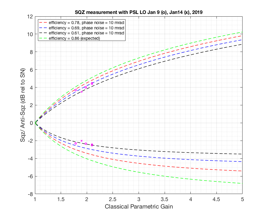
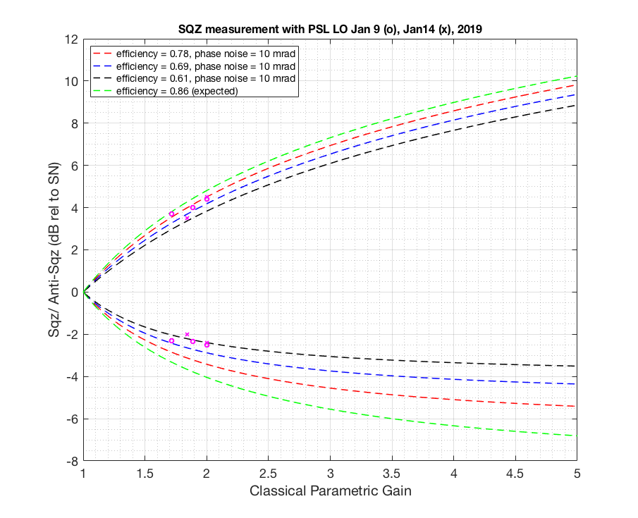
Previously in alog46336 I felt like I was bottomed out on some of the measurements phase delay wise. To get more phase delay so we can be more confident in our measurement I gave 3MHz phase delay box to CLF (I have a feeling that phase delay box hooked up to LO/OMC gives me a bit less phase, not sure if that make sense, I will post more detail alog on the ellipse rotation later). Add CLF sign flip on top of that (which gives us extra 90 degree as Daniel suggested) I was able to go from OK to GOOD then back to OKAY measurement on both squeezing and anti squeezing. Flipping LO sign didn't help (180 deg). And using Q error signal to lock the CLF seems to have given me some extra phase adjustment (not sure why, CLF common mode board input 2 now has Q error signal goes into it). This way I know that I've seen the best sqz/asqz (by monitoring LO Q error signal go up and down while adjusting the phase, we locked with I).


After correcting for some of the minor loss typos and added data taken yesterday after I've acquired more phase delay, here I attached another loss estimate plot. I also give phase noise of 10 mrad this time since assuming that what we measured out of the LO IMON isn't all the phase noise there is. The result hasn't changed. We have more loss compared to when Haocun took a measurement here. We are still in the process of checking red transmission then and now.


Fringe visibility during Jan14 measurement was 99%. In the model I use 97%.


Images attached to this report
Non-image files attached to this report
Comments related to this report
nutsinee.kijbunchoo@LIGO.ORG - 16:48, Tuesday 15 January 2019 (46446)

Before the measurement our laser was running multimode again. To get away from multimode I moved the current knob from 2.193A to 2.207A. Temperature stays the same (29.65C). This gives 158MHz without having to put a lot of offset to the control loop (ended up with -7MHz).  

nutsinee.kijbunchoo@LIGO.ORG - 18:02, Wednesday 16 January 2019 (46487)

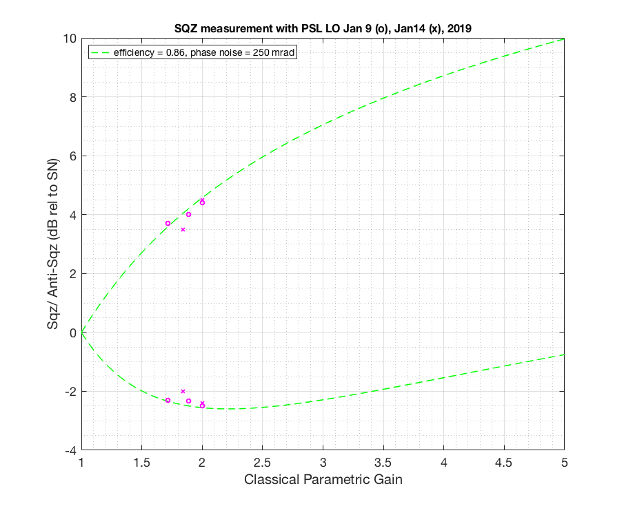
I went back to double check if my nlg was correct and found that the dark noise was actually negative (I missed a minus sign when I subtracted the DN). So here attached a revised plot. That didn't change the result (sadly). I also attached a plot projecting how much phase noise would you need in order to explain what we observe if we were to let efficiency by 86%. You need at least >250 mrad to explain what we have (which is not what we observed in LO error signal).


Images attached to this comment
H1 ISC (ISC)
craig.cahillane@LIGO.ORG - posted 02:46, Sunday 13 January 2019 - last comment - 18:32, Wednesday 16 January 2019(46386)
Calibration of True Input Power
I have been wondering about the true input power, i.e. the input power incident on PRM, ever since the SRCL dither arm power measurement turned out so low.  

Conclusion
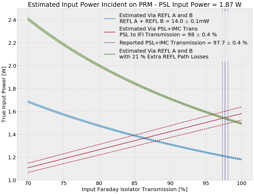
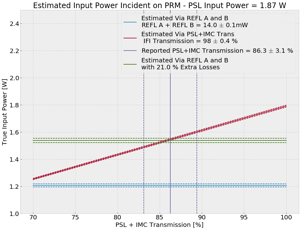
With an input power of 1.87 watts according to the PSL photodiode, we probably have around 1.55 watts incident on PRM, assuming an addition 21% unaccounted losses in the REFL A/B LF PD path.

Power Measurement Methods
I aligned PRM and the input optics, and misaligned the rest of the corner with 1.87 W reported from the PSL input power PD going into the IMC.

IM4 Trans
The easiest way would be to get Pinput would be via IM4 TRANS.  IM4 TRANS is calibrated into microwatts, IM4 (aka SM2) transmission is reported to be 2400 +- 200 ppm, and there's what I think is a 90:10 BS (ROM LH1) allowing 10% of the light going to IM4.  However, if we turn the crank here we end up with only 0.2 W, which is not possible.  This means that IM4 TRANS is not calibrated correctly, or the IM4 transmission path is actually around 8 times less transitive that I though.

REFL A/B LF
We believe that the REFL A/B LF PDs are correct based on the calibrated CARM shot noise.  We can use them to calibrate the correct input power.  The main issue here is if we use the REFL optical path (4 50:50 beamsplitters, 1 90:10 beamsplitter, one input faraday isolator, and one PRM) and assume no losses, we only get 1.19 W of true input power on the PRM.  This could be the case, but it's more likely that there are some unaccounted for losses on the REFL path.

PSL and IMC Transmission
If we trust the old numbers from P1500076 on the PSL and IMC transmission, we can make an estimate of the true input power.  We find that by varying the PSL and IMC transmission, we cannot reasonably recover the REFL A/B power levels we see.


PD Powers and Optic Transmissions Assumed
# Most taken from P1500076

# PD calibrated powers
PSL_INPUT = 1.87 # W
REFL_A = 7.3e-3 # W
REFL_B = 6.72e-3 # W
IM4_TRANS = 50.24e-6 # W

# PD uncertainties
dREFL_A = 0.04e-3
dREFL_B = 0.03e-3
dREFL_SUM = np.sqrt(dREFL_A**2 + dREFL_B**2)

# Transmissions
T50 = 0.5
T10 = 0.1
T_PSL = 0.953 # +- 0.013 PSL to MC1 transmission
T_IFI = 0.977 # +- 0.004 https://dcc.ligo.org/DocDB/0119/P1500076/003/Mueller16rsi-AdvIO3.pdf
T_IMC = 0.92  # +- 0.031
IMC_ModeMatching = 0.984 # 0.001
T_PSL_to_IFI = T_PSL * T_IMC * IMC_ModeMatching
T_IM4 = 2400e-6 # +- 200e-6 E070092
T_PRM = 0.031 #

# Trans Uncertainties
dT50 = 0.01
dT10 = 0.01
dT_PSL = 0.013
dT_IFI = 0.004
dT_IMC = 0.031
dIMC_ModeMatching = 0.001
dT_PSL_to_IFI = np.sqrt( T_PSL_to_IFI**2 * ((dT_PSL/T_PSL)**2 + (dT_IMC/T_IMC)**2 + (dIMC_ModeMatching/IMC_ModeMatching)**2) )
dT_IM4 = 200e-6
Images attached to this report
Comments related to this report
craig.cahillane@LIGO.ORG - 14:47, Monday 14 January 2019 (46403)
This calibration is now implemented in H1:IMC-IM4_TRANS_{SUM,PIT,YAW} FM10.
daniel.sigg@LIGO.ORG - 17:31, Wednesday 16 January 2019 (46485)

The IM4_TRANS is no longer calibrated in µW due to a gain change in the whitening. The calibration dates back to alog 9716, where the whitening gain was 36dB. It is 18dB now, so the "µW"-readbacks are 18dB too low.

We added NSUM channels to the IM4 and MC2 Trans QPDs to facilitate an additional calibration of the incident power onto these mirrors.

craig.cahillane@LIGO.ORG - 18:32, Wednesday 16 January 2019 (46491)
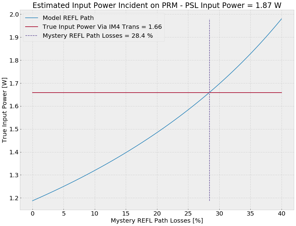
With this additional 18 dB of whitening gain, we can calibrate true power input the simple way using IM4 TRANS:

Requested Laser Power = 2 W
PSL Reported Power    = 1.87 W
T_IM4                 = 2400 ppm
True Input Power      = 1.66 W


If we let T_IFI = 0.977, T_PSL = 0.953 and IMC_ModeMatching = 0.984, then T_IMC = 0.968.

And the mystery REFL path losses are 28.4% (see attachment).
Images attached to this comment
Displaying reports 43501-43520 of 88617.Go to page Start 2172 2173 2174 2175 2176 2177 2178 2179 2180 End