As a sanity check we measured the loss on the homodyne path on SQZT6: Loss = 10.7mW/430mW = 2.7% from 4 mirrors + beamsplitter + 3 lenses.
Seed power to homodyne = .430 mW (between measured between periscope mirror1 and periscope mirror2)
.272 mW. and .269 mW on each homodyne diode (seed + LO)
59.5 and 62.2 respectively on each diode (LO only).
Diode 1 seed = 272-59.5 = 212.5 ; Diode 2 seed = 269-62.2 = 206.8: Total seed power on both diodes = 419.3
Loss = 10.7mW/430mW = 2.5% from 4 mirrors + beamsplitter + 3 lenses.
Note I discovered we currently have no beam dumps before homodyne for parasitic interferometry, this should be addressed but is unlikely to be the cause of our loss issue.
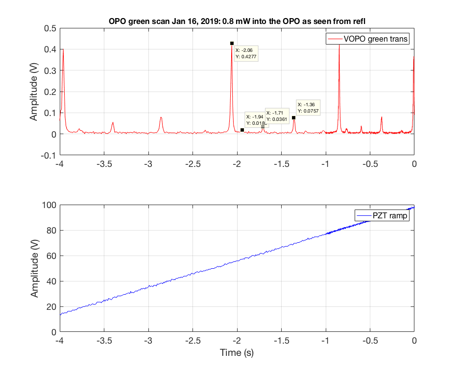
After we closed out HAM6 we took a scan to ensure our alignment were good (alog45372). Our 00 mode was 88.2% then. Today I took another scan and turns out our 00 mode is now down to 78%. That's 10.2% drop.
I put 20dB attenuator on the 80MHz LO during this measurement so I can compare directly to a scan from out close out log. The attenuator has been taken out.

Also remember when the last fiber started to degrade right before the vent there was some strange mode degradation 44663
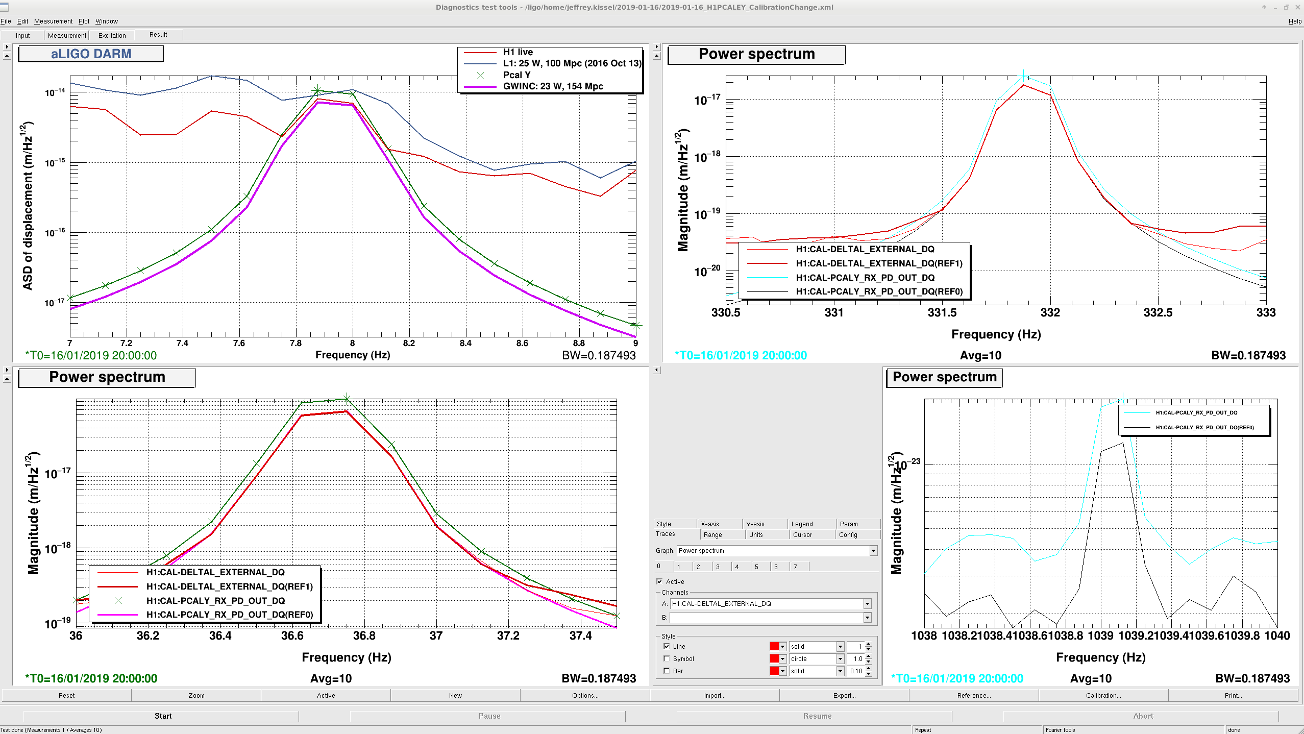
S. Karki, J. Kissel, R. Savage After hitting nominal low noise this afternoon, I noticed that PCALY RX PD was not lining up well with CAL-DELTAL_EXTERNAL on the wall FOM -- the PCAL was over estimating it's "meters" by a factor of ~1.4 (we know it was a PCAL flaw because nothing had changed in the DARM loop, nor in the DELTAL_EXTERNAL calibration). Rick, Sudarshan, and I quickly found an honest mistake in their implementation of the newly "exploded view" of the calculation of the Newtons / RXPD Volt (implemented yesterday LHO aLOG 46449) -- namely, one component of the calculation, the ratio between the working standard and each EY RX and TX PDs, were flip-flopped (channels H1:CAL-PCALY_FORCE_COEFF_ALPHA_R and H1:CAL-PCALY_FORCE_COEFF_ALPHA_T). Finding the mistake, they updated the list of EPICs records, (and changed the content of the attachment in LHO aLOG 46449 without changing the name), so I've copied it to Cal repo, so now lives (and committed) here: /ligo/svncommon/CalSVN/aligocalibration/trunk/Runs/O3/H1/Results/CALCS_FE/lho_yend_pcal_epics_created-20190116.txt which has been run, installed, and accepted into both the SAFE.snap and OBSERVE.snap files for h1caley. We're back in nominal low noise, and the PCAL RX PD lines now line up well with DELTAL_EXTERNAL. Problem fixed.
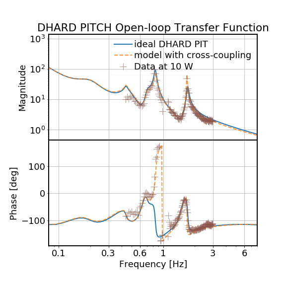
In LHO:46179 we reported an anomalous phase advance in the DHARD PIT OLTF at ~ 0.8 Hz.
It turns out that such a feature can be modeled by including cross-couplings in both actuators and sensors. Please see the attached plot.
In the model we considered the single-arm case which is equivalent and the X and Y arms are balanced. On the other hand, we assumed the ETM has an actuation strength 10% stronger than the ITM, and each soft mode angle we sensed was actually one ideal soft mode minus one ideal hard mode. Without any fine-tuning of the parameters, the model taking into account the cross-couplings almost perfectly matched to the measurement data.
===================================================
The mathematical details were also attached (actImba.pdf). The basic idea is to project all the quantities with imperfections onto the ideal hard-soft basis (also note that the hard/soft radiation feedback is independent of the strength of actuation magnets), and then extend the regular SISO loop analysis to the MIMO case. The latter is easily achieved by replacing the vector transfer functions into transfer matrices. The effective oltf is then obtained by first finding the close-loop response and then use oltf= 1/cltf - 1.
NikoL, Dimitri Estevez (Virgo), SudarshanK (remotely), RickS
This morning, we calibrated the Yend Pcal readback channels using the working standard (WSH) that we had delivered to Yend yesterday afternoon and left powered up overnight.
We encountered a couple of software issues related to the updates to calculate the force coefficients in the frontend, but we were able to complete the measurements.
The power sensor coefficients calculated today were very close to the values we calculated from the measurements made on December 13.
| Sensor | Dec. 13 | Jan. 15 | ratio (new/old) |
|---|---|---|---|
| Tx (V/V) | -0.480810 | -0.480448 | 0.99925 |
| Rx (V/V) | -0.715832 | -0.715410 | 0.99941 |
We decided to go ahead and switch to using the force coefficients calculated in the frontend (using JeffK's new code). We updated the epics values using the data from our Dec. 13th measurement and captured in the .txt file attached in that entry. We "put" the values into the epics records by just copying and pasting the text in the lho_yend_pcal_epics_created-20190115.txt file attached to this entry and in the SVN at
/ligo/svncommon/CalSVN/aligocalibration/trunk/Runs/O3/H1/Results/CALCS_FE/yend_pcal_epics_created-20190115.txt
The new Pcal power sensor calibration values (N/V) and comparisons with the previous values are:
| Force coeff. | New | Prev. | ratio (new/old) |
|---|---|---|---|
| Tx (N/V) | 1.5049e-9 | 1.5160e-9 | 0.9927 |
| Rx (N/V) | 1.0223e-9 | 1.0475e-9 | 0.9759 |
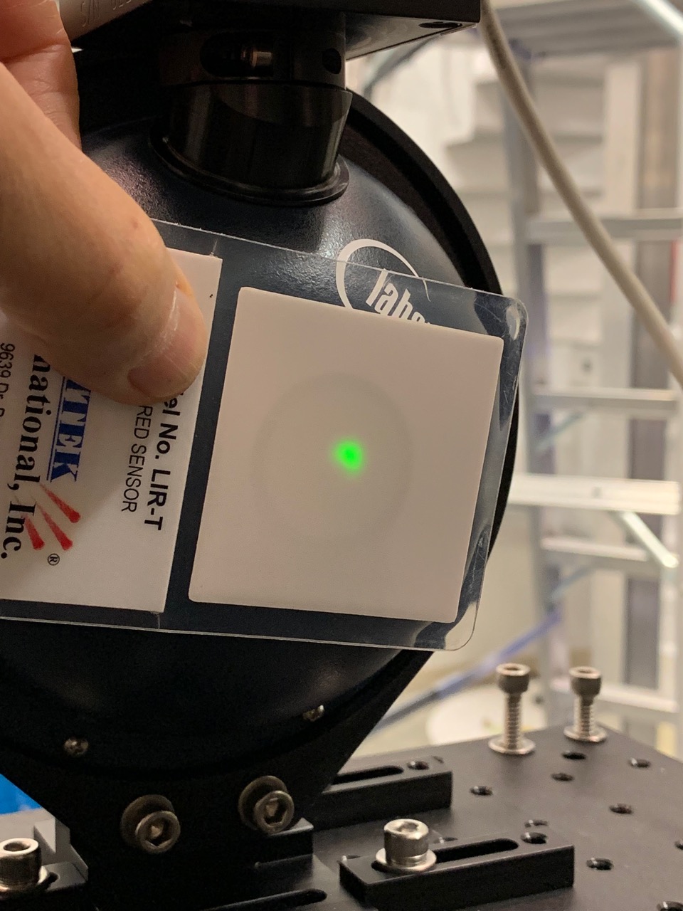
We checked the beam spot locations on the Rx power sensor aperture. The beams are reasonably well centered; both beams are incident on the integrating sphere in the attached photo.
Notes from today's Pcal calibration work attached below.
One of the end station calibration procedures involves using the Martel voltage supplier at both the end station and the LSB lab to calibrate voltage measurements. The output from the LSB lab measurements is:
|
WSH |
Input (from Martel) [V] |
Output (from Keithley) [V] |
|
-4 |
-4.0001 |
|
|
-2 |
-2.0001 |
|
|
-1 |
-1.0001 |
|
|
0 |
0.000008 |
|
|
1 |
1.00001 |
|
|
2 |
2.0001 |
|
|
4 |
4.0001 |
The attached text file to the main entry, called out stored in the CalSVN repo as /ligo/svncommon/CalSVN/aligocalibration/trunk/Runs/O3/H1/Results/CALCS_FE/lho_yend_pcal_epics_created-20190115.txt *had* had a bug in it -- see LHO aLOG 46472. After finding the bug, the contents of the file were replaced in the above attachment, and it was run and installed in the front-end. For posterity, I've saved the file as a new name in the Cal repo: /ligo/svncommon/CalSVN/aligocalibration/trunk/Runs/O3/H1/Results/CALCS_FE/lho_yend_pcal_epics_created-20190116.txt
This last lock, we got to 30W just fine, but lost lock just before nominal low noise, at the CARM gain increase. Sheila mentions that the increased CARM gain was put into the guardian last night, but that the measurements showing that gain is okay were taken after we'd thermalized. It's possible that we can't put in the extra CARM gain until we've lost enough 9MHz buildup.
I reverted the CARM gain increase in guardian, and we locked just fine.
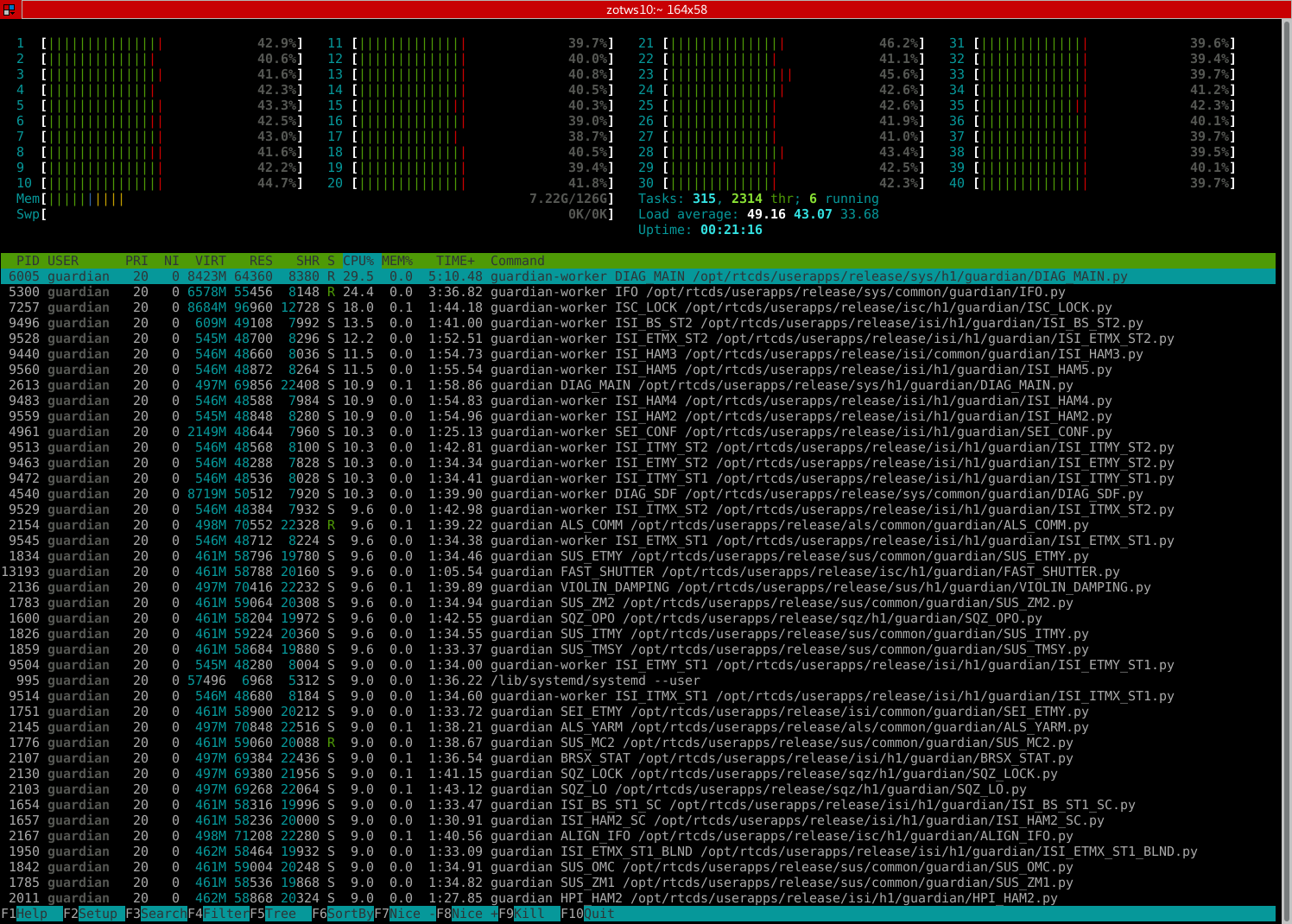
We just moved h1guardian1 to new hardware, with more CPU and memory. The guardian system is being recovered now.
The new machine has 20 hyperthreaded cores (Intel Xeon 2640 V4 2.4GHz) and 128G of RAM. This is about twice the resources of the old machine.
The old machine was seeing frequent (couple of times a day) EPICS channel connection drop outs, which would cause EZCA connection errors on the guardian nodes and problems locking. The load on the old machine was very high (>90% load on all 10 CPUs constantly), and the theory was that that was contributing the EPICS connection issues. We should have considerably more headroom on this new machine, which will hopefully ameliorate the EPICS issues.
htop on the new machine:

TITLE: 01/16 Day Shift: 16:00-00:00 UTC (08:00-16:00 PST), all times posted in UTC
STATE of H1: Commissioning
OUTGOING OPERATOR: None
CURRENT ENVIRONMENT:
Wind: 3mph Gusts, 2mph 5min avg
Primary useism: 0.02 μm/s
Secondary useism: 0.38 μm/s
QUICK SUMMARY:
Koji, Craig We had a nine hour lock today. Koji and I went out on the floor 10:20 UTC in order to measure CARM and IMC OLGs and spectrum, and killed it by the time we had walked around to the PSL racks. We were aware of the possibility of lockloss, and took great care to be as nimble as possible, so this is not great, completely prohibitive to in-lock rack work. In the recent past, we had not been so sensitive to LVEA incursions during full lock. Not sure what has changed. All LSC, ASC, and dither loop error signals seem within reasonable range. IMC_F has a large excursion to -400 kHz directly before lockloss, simultaneous with our excursion. Most likely possibility in my mind is us walking around disturbed the IMC. Have there been any changes to HAM2 or 3 isolation?
Craig, Georgia, Danny, Sheila
We have re-tuned the SRCL feedforward for 30 W interferometer configuration. The updated feedforward reduced SRCL coupling to DARM from 60Hz to 500Hz (driven measurement shown in final attachment).
We measured the transfer function from SRCL to DARM without feedforward, and from the SRCL-FF path to DARM, using templates found here:
/opt/rtcds/userapps/release/lsc/h1/scripts/feedforward/
We then used Craig's ipython notebook to fit these transfer functions and calculate the feedforward filtering required to cancel SRCL noise in DARM. The notebook is found here:
/ligo/home/craig.cahillane/Git/Feedforward/SRCL2DARMfeedforward.ipynb
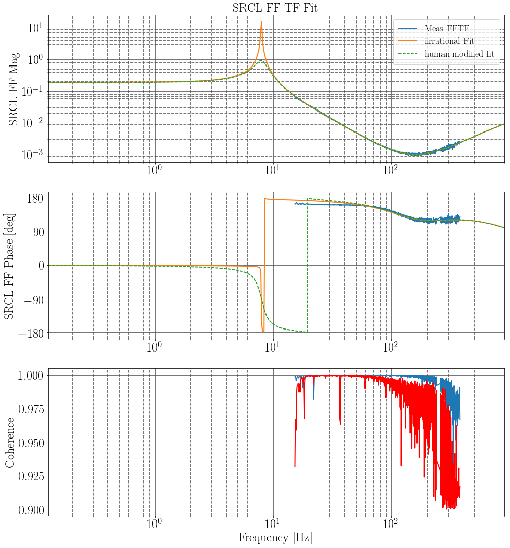
This notebook uses iirrational to fit the transfer functions. We added some human tweaking to the fit to minimise the resonant peak at ~8Hz. First attachment shows the data (blue), iirrational's fit (orange), and the human-modified fit that was implemented in the feedforward filter (green). Note that the fit to the phase of the TF is not good below 60 Hz, so perhaps there is room for iterative improvement on these filters.
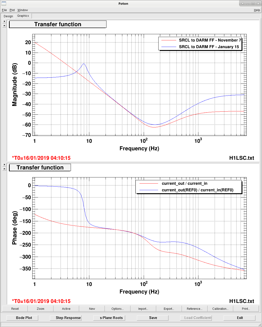
The second attachment shows the old SRCL-FF filter (Nov7) compared to our new filter (Jan15).
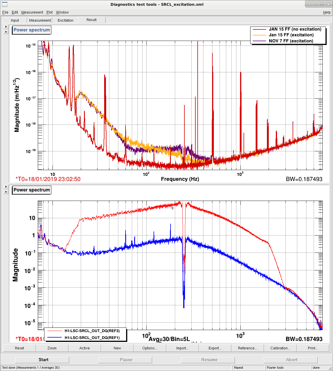
The final attachment shows the SRCL to DARM coupling reduction: yellow is DARM (and SRCL) with no excitation, blue is with the old feedforward, purple is the new feedforward.
Attached is a similar measurement but on 1/18/2019. Not exactly the same excitation but close enough to show that with the same feed forward filter the SRCL noise is higher (between 60 and 450 Hz) than it was when we took this measurement a couple of days ago.
Georgia, Koji, Jeff K, Sheila
We made a couple of small updates to the OMC_LOCK guardian and omcparams:
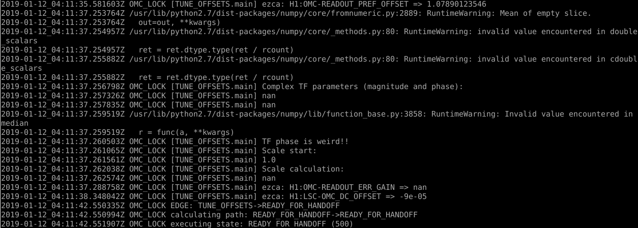
We had a lockloss straight after transitioning to DC readout. Looking back at the guardian log (first attachment) we see that in the TUNE_OFFSETS state, where the guardian measures RF DARM to OMC transfer function and sets some gains to match them, the transfer function failed and some channels are set to nan. I'm not sure yet what IFO conditions created this condition, but we added an error flag to the TUNE_OFFSETS state to prevent the OMC from proceeding to READY_FOR_HANDOFF if the TF fails.
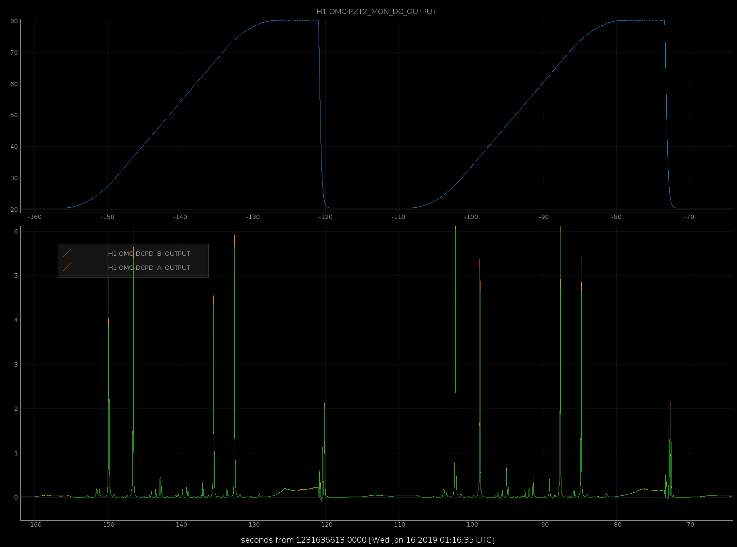
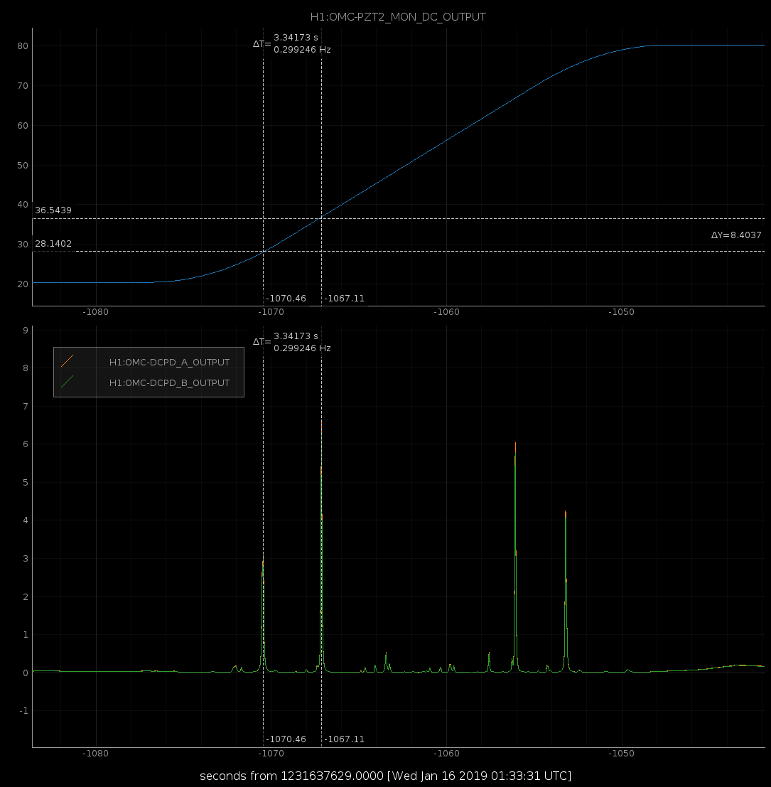
The OMC guardian has been having trouble finding the carrier on its own in the last ~week. In FIND_CARRIER it sweeps PZT2 and looks at the DCPD's, first finding the two 45 MHz sidebands and then searching for the carrier halfway between them. The current offset on PZT2 for the carrier resonance is ~77V, and the scan sweeps from 20-80V, it looks like in our current sweep range we only see one 45 MHz sideband and the carrier. The second attached photo shows the data for two sweeps, third is zoomed into one sweep. I will reduce the starting PZT offset in omcparams so that we sweep through both 45 MHz sidebands on the lower (~28V) carrier resonance, given past issues with 9MHz higher order modes resonant at large PZT offsets.
Sheila, TVo, Georgia, Craig, Danny
This current ASC situation seems better than what we've had the last several days, so we probably want to make some of these changes permanent, but we don't want to make any changes in the guardian since ASC engagement has been tricky and we may not have a chance to test things. I think that turning off PRC1Y, and increasing the CHARDY gain from 3 to 6 are definitely improvements. The change to the CSOFT input matrix I'm not so sure about.
I've put the CHARD_Y gain increase and the PRC1_Y loop-off at the end of ENGAGE_SOFT_LOOPS. I have not changed the SOFT input matrix.
In addition, since we haven't been using the DSOFT_P loop lately, I've told the guardian to stop turning on the DSOFT_P radiation pressure compensation. Now, when guardian is turning on the RPC stuff, if the DSOFT_P gain is zero, then it skips over DSOFT.
Summary: BRUCO gave us a few interesting clues about our current noise, including a broadband contribution to the DARM noise that seems to couple through the 9 MHz sideband.
We had 20 minutes of glitch free data from 1231532246 to 1231533411. This was before Georgia and Danny fixed the ISS second loop clipping 46412, which improved the noise from 27-15 Hz and around 350-400 Hz. Gabriele and Joe Areda managed to run BRUCO (and update the code to deal with some other updates), a report is here: https://ldas-jobs.ligo.caltech.edu/~gabriele.vajente/bruco_lho_1231532246/
Some interesting features (other than the ISS coherence)
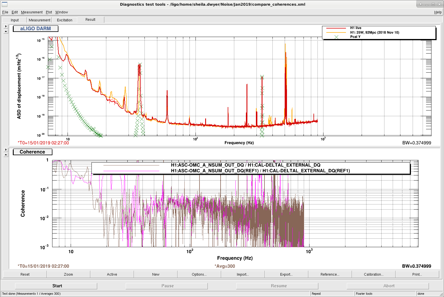
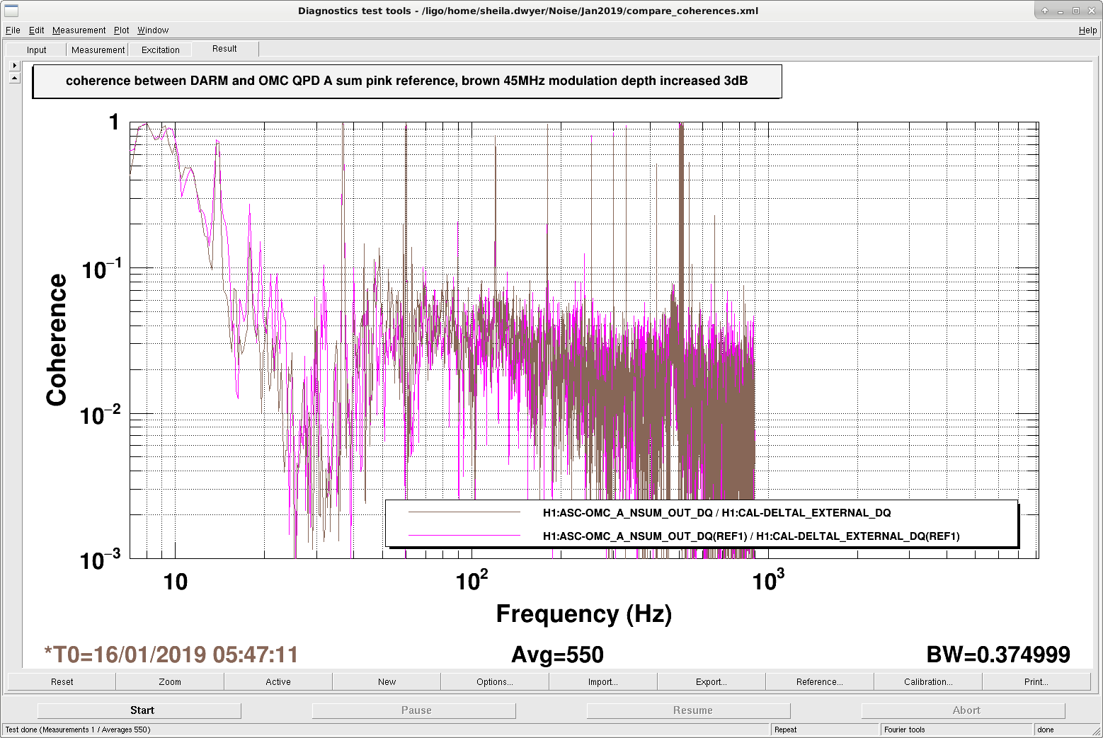
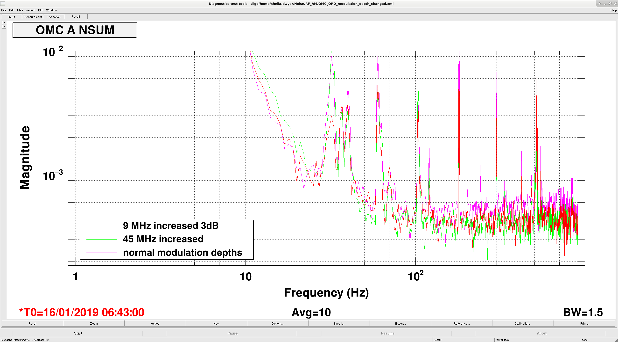
Sheila just engaged a second stage of whitening for the OMC QPDs, so hopefully that will address the coherence there. We can't just add DC gain, at least until the 45 MHz modulation depth is reduced, otherwise we'll saturate the diodes.
Our nominal powers on the EOM driver right now are 20dBm for 9 MHz, and 23.6 dBm for the 45 MHz. (Those were the driver powers before we started changing things last night).
By looking at the DC power on the OMC QPDs while we were changing the modulation depths last night we can find the relative powers in (carrier+118), 9 MHz and 45 MHz.
| carrier | 45 MHz power | 9 MHz power | |
| OMC QPD A | 23% | 67% | 9.7% |
| OMC QPD B | 19% | 74% | 7.4% |
The attached spectrum comparison shows that the noise on the OMC QPD didn't increase in when the 9 MHz modulation depth was increased. This means that the 9MHz amplitude noise is not the dominant noise in the OMC QPD, so we can't make that assumption to make a projection of the 9MHz amplitude noise into DARM.
I ran the IMC a2l script, and some gains changed so much that I was not confident that they were correct, because the IMC optics OSEM values had not changed more than 5urad, so no large gain changes were expected. I started another measurement, but it did not finish, so the current gains are ok enough, but could be updated tonight when there's a lock loss, or in the morning I'll revisit.
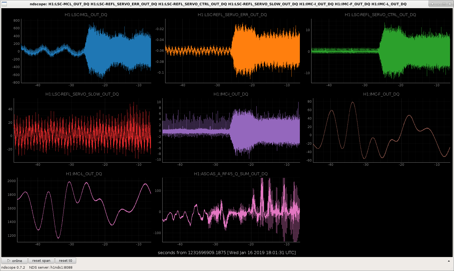
During the several hour lock over night, that I found the IFO in this morning there were some strange combs in the CARM signals.
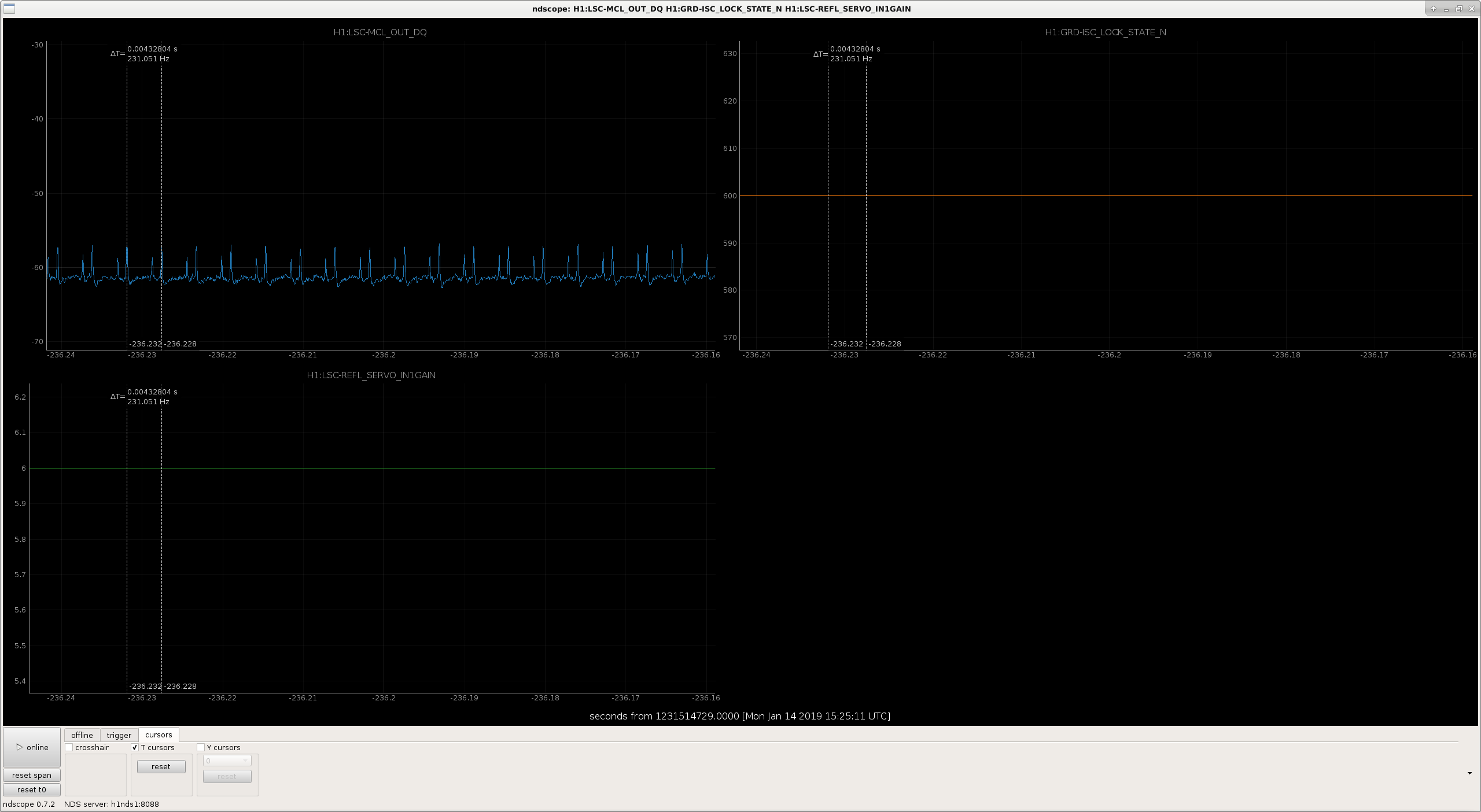
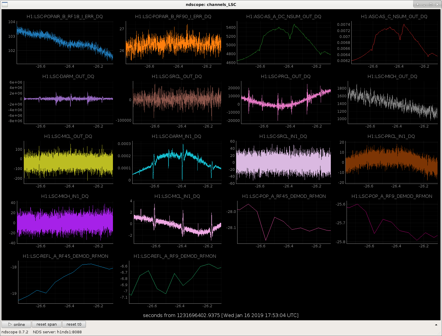
The particularly strange thing is that I see these spikes in the LSC-MCL signals for that lock first thing this morning, but haven't really seen them in any later locks today. During the lock that the spikes are there, there are a few times that the spikes go away for 2-4 sec, but they always came back. In the next lock, the spikes were almost never there, but did come in 2 or 3 times for 1-2 sec, but then went away again. Between these 2 locks, I'm not aware that any configuration changes were made to the CARM system.
The SR785 was plugged in to the IFO common mode board, and the excitation input was enabled, so it's possible that the SR785 and whatever mysterious grounding problems we've been having are the culprit. But, since the SR785 wasn't unplugged until much later in the day, I'm not so sure. Anyhow, we're going to try to make a habit of unplugging any instruments from the ISC racks as soon as a measurement is complete, just in case.
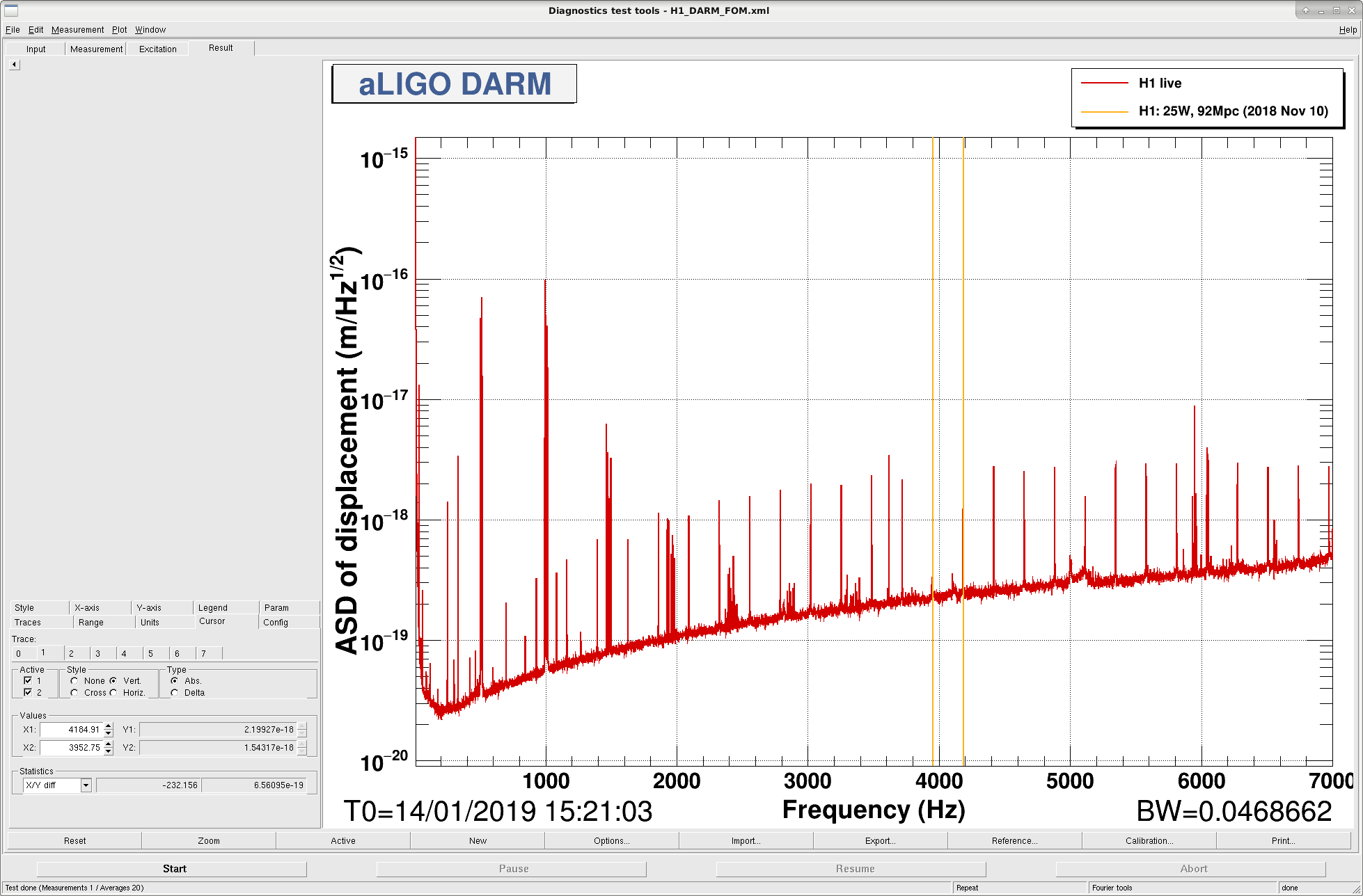
It looks to me like there are 2 different combs, both very near 232 Hz, but they are drifting in time relative to one another. See attached DARM spectrum with the giant comb, as well as ndscope screenshots from 2 different times during the same lock. The ndscope screenshots also show that the IFO is in the same state (NomLowNoise) for both of these times. No gain sliders in the common mode or IMC servo boards were being moved either.
These spikes could be causing me to repeatedly lose lock when I try to transition DARM to RF (CARM is already on TR at this point). The spikes that I see in MCL are also showing up clearly in PRCL, and are definitely present in DARM.
UPDATE: The second figure is from a time when I'm transitioning CARM off of the ALS signals and onto the IR transmissions. During this time, the spikes begin to be impressed on AS45, which is the signal that we'd use in the next step for DARM. So, the AS signals don't have the spikes natively, but they do show up once the spiky signals are used for CARM.
Also, both the SR785 and AG4395 were plugged into the CARM and IMC boards respectively. I had ndscope open on the workstation by the racks, and was watching the spikes while the IFO was locked on ALS, with DRMI locked. When I wiggled the cable connections at the analyzers, I did not see any effect on the spikes. I then unplugged the IN2 cable from the IMC board (at the chassis), and saw no change. Next I unplugged the EXC cable from the IMC front panel, and the spikes immediately went away. This was repeatable, re-introducing the cable brought the spikes back, removing the cable removed the spikes. Note that the excitation point on the board was disabled, but somehow the Agilent is still causing noise. It didn't look like the Agilent was taking any measurement, it was just passively plugged in. I unplugged the 3rd cable from the IMC chassis, as well as all 3 cables from the CARM common mode board just for good measure. The SR785 and AG4395 are still on, but they are not cabled to any IFO electronics.
With the SR785 and AG4395 unplugged, I do not see regular spikes on MCL. However, when doing the CARM and DARM to IR transitions, I did see the spikes come back for a few seconds, but then they're gone again. So, there may still be something going on (does the Agilent need to be turned off entirely?), but it's much better now. I have not had any trouble locking since.
Moral of the story - we can't leave the AG4395 plugged in to the IMC common mode board, even if the excitation input is disabled. Needing to turn the RF analyzer off, or also forbidding the SR785 is still a possibility, but not yet proven.
Separately, while I was standing next to the ISC racks, I noticed that if I took a step (heavy step, but not stomping) I could see a buzz of noise in both the IMC signals and AS45, despite our still being locked entirely on ALS for the arms. I did not check how close / far I had to be from things to see this, but if we're getting a big burst of noise just from walking with anything but the most gentle of steps, perhaps that's a clue we can use to figure out why we are so sensitive lately.
SudarshanK, RickS
We completed calibration of the Pcal power sensors at EndY today using the new Working Standard (WSH). This calibration also incorporates the changes we made to the Pcal Tx and Rx power sensors on Tuesday (LHO alog 45876). The results of this set of endstation calibration measurements can be found in the attached text file.
All the data, plots and the intermediate results from this calibration measurement can be found at https://svn.ligo.caltech.edu/svn/aligocalibration/trunk/Projects/PhotonCalibrator/measurements/LHO_EndY/D20181213/
Using these measurements plus the Working Standard to Gold Standard responsivity measurements, new Gold Standard measurement from NIST (-8.0985 V/W) and the in-vacuum optical efficiency measurements we did during the vent, the force coefficients for the Pcal TxPD and RxPD in N/V are:
TxPD : 1.5049E-09 N/V
RxPD: 1.0223E-09 N/V
The previous values used during O2 and still implemented in the filter files are:
TxPD : 1.5160e-09 N/V
RxPD: 1.0475E-09 N/V
They differ from these new values by about 0.7 and 2.4%, respectively.
We are not going to update the calibration at this time. We will wait until the next long lock opportunity to test the new values by comparing with X-End Pcal.
The parameter file that is required to generate the force coefficient in the front model is attached as well. Note: We have left the TX and RX (AA) gain factor as 1.
Two values on the attached 20181213LHOY_Pcalparam.txt file were swapped. The correction is below:
OLD ENTRY H1:CAL-PCALY_FORCE_COEFF_ALPHA_R = -0.4808 H1:CAL-PCALY_FORCE_COEFF_ALPHA_T = -0.7158
CORRECT ENTRY: H1:CAL-PCALY_FORCE_COEFF_ALPHA_R = -0.7158 H1:CAL-PCALY_FORCE_COEFF_ALPHA_T = -0.4808