Restarted CW hardware injections at GPS 1231624918 (Jan 15 2019 22:01:40 UTC). They seem to have crashed on January 8 (maintenance disruption?). It would be good to get monit running so that restarts occur automatically.
A few weeks ago I noticed my daily build was reporting adcparser errors with h1asc. The parts array was of fixed size=5000 and h1asc had grown to about 5200 parts. I increased the limit to 6000.
Yesterday I noticed the error had come back, and sure enough h1asc had grown to 6894 parts. As a side note, this seems to be a rather large increase in a short amount of time.
I have bumped up the limit from 6000 to 10,000
I'd never heard of this parts limit before. The smooth limiters (which have now been put in on the inputs of the ADS servos, since we're using them as part of the ASC system more now) have about 100 parts per limiter. There are 10 each of pitch and yaw loops in the ADS system, so today I added about 100*20 = 2000 parts (if you count "GoTo" and "From" flags, and mux and demux all as individual parts). This work was done as part of WP 8047.
Since we were booting the ASC model anyway for this work, Keita pulled all of the ODC parts out of the ASC model.
Following the h1odcmaster changes, the EPICS channel H1:ODC-OBSERVATORY_MODE was removed. I created a new EPICS IOC on h1fescript0 called h1_observatory_mode.py which now hosts this channel. A new DAQ INI file was created called H1EDCU_OBSERVATORYMODE.ini so DAQ can trend this channel. This was done after the last DAQ restart so will not go into effect until next Tuesday.
At LLO, we'll likely host this on the same DAQ Utility server that will host the run_number server and planned Dolphin network manager
WP7929 SEI senscor
Jim W, Jeff K, Dave:
new models for h1seiproc, h1isi[itmx, itmy, bs, ham2, ham3, ham4, ham5, ham6] and h1hpiham1 (ISI component thereof) were installed. DAQ restart was required.
WP8040 new h1calinj model
Jamie, Jeff K, Dave:
A new model (h1calinj) was installed on h1oaf1 and added to the DAQ. It has been added to the aux EDCU files and the CDS overview MEDM. Still needs to be added to SDF and IPC overview MEDMs. DAQ restart was required.
tcscs ring heater updates
Danni, Dave:
A new h1tcscs model was installed on an open WP. DAQ restart was required.
WP8046 h1calcs bug fix
Jeff K.
A new h1calcs was installed, DAQ restart was required.
WP8047 ASC input limiters
Jenne, Keita, Dave:
a new h1asc model was installed, DAQ restart was required.
General ODC cleanup
Jamie, Jeff K, Keita, Dave:
ODC channels were removed in the corner and end stations. h1odcmaster, h1calex, h1caley, h1iscey models were restarted. DAQ restart required.
DAQ
Dave:
DAQ was restarted in two phases. First reboot at 08:33PST was to cover ISI and CAL-CS changes done first thing this morning.
The second restart at 12:37 covered the TCS, ASC, ODC, CAL, ISC changes and added h1calinj to the DAQ for the first time.
WP8041 GDS OS upgrade
Greg:
Greg upgraded all GDS/DMT machines to SL7.6. Machines were rebooted and monitors restarted.
I loaded all outstanding filter changes for the h1psliss model.
Stefan, TVo, TJ, Danny
Before the break we created a guardian (TCS_RH_PWR.py) and adjusted the model that allowed the the user to choose between two states:
NOMINAL_RH_INPUT: allows the user to manually input ring heater power
FILTER_RH_INPUT: allows user to adjust the RH power using the inverse RH filter (alog 44243)
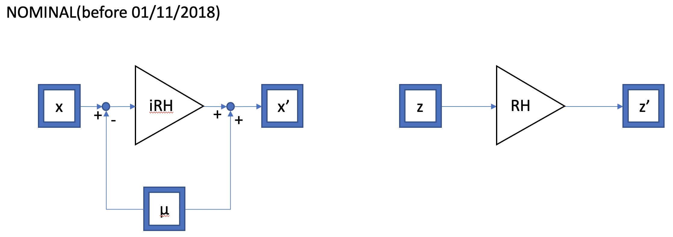
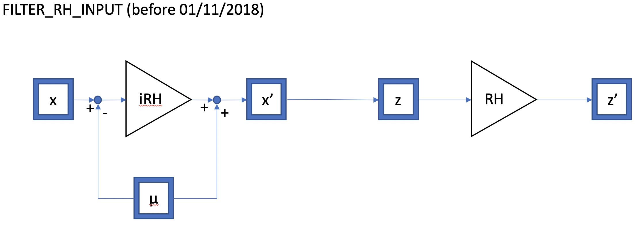
The guardian had a few flaws. In FILTER_RH_INPUT, it did not allow the user to input multiple RH settings until the prior ring heater change had reached its nominal value. The following controls diagrams show what these states used to do:


Where iRH is the inverse RH filter, RH is our plant, and µ is the subtracted DC offset (prior RH setting before a power change was requested). x and x' represent the iRH filter input and output respectively and z and z' represent the plant input and output respectively.
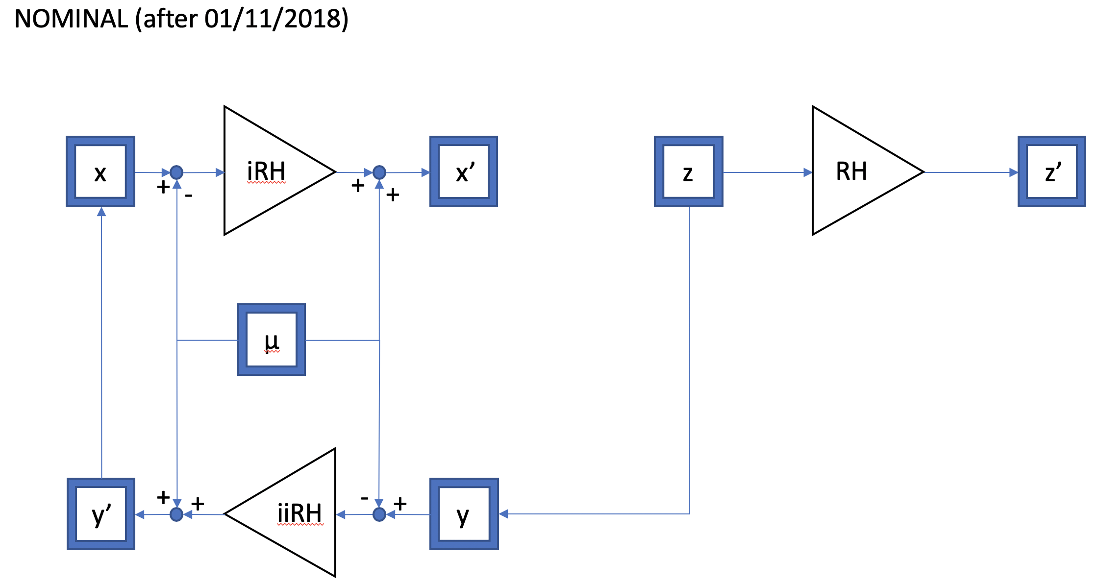
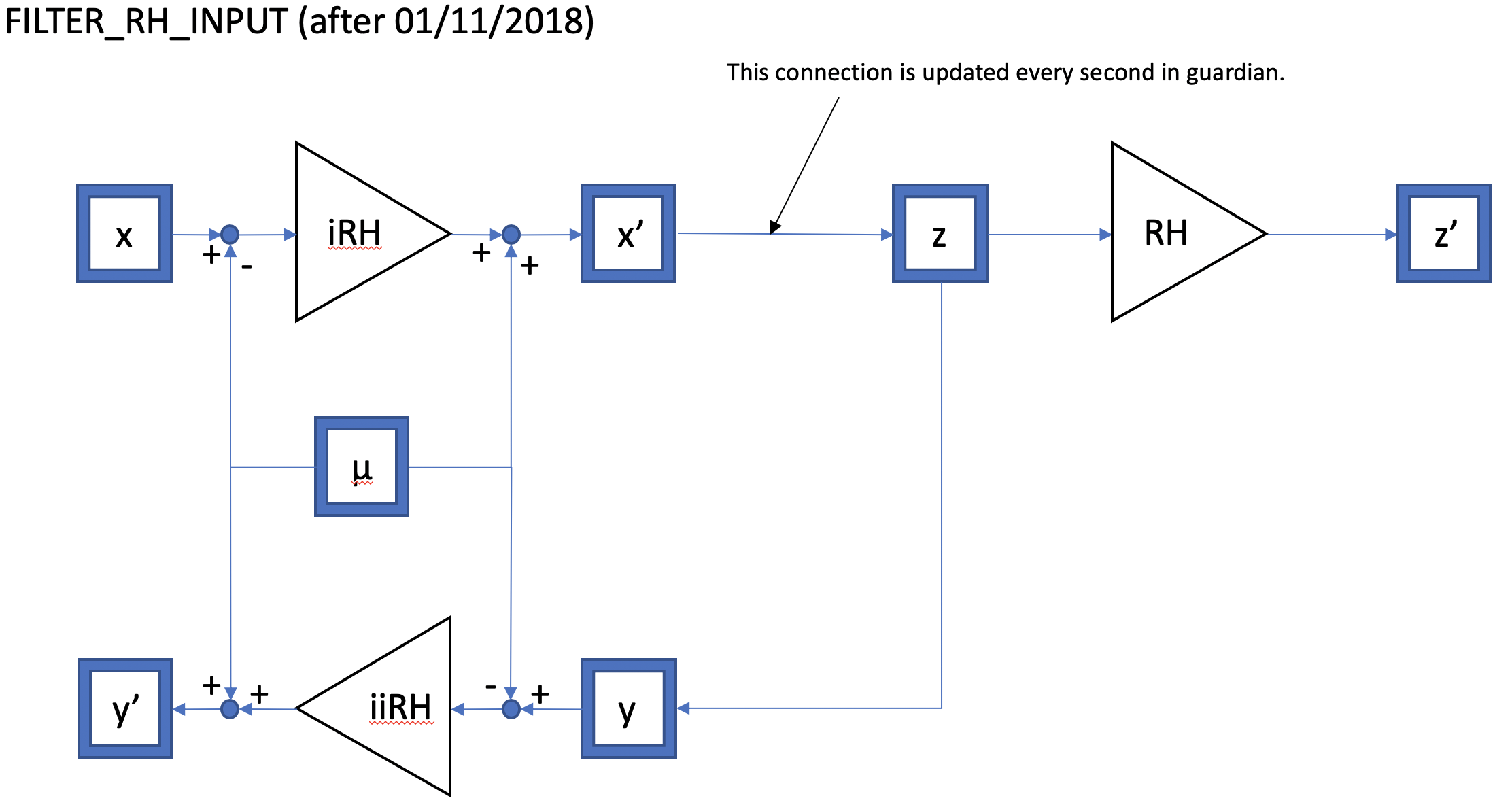
Stefan and I thought a bit about how we can make the ring heater control more robust. We wanted to create a design that allows the user to, in principle, make any number of changes within a given period of time and have the RH acquire the desired lens within a 2.5 to 3 hours from the last change as well as keep track of the history of the numerous requests . The following diagrams show the updated changes made to the h1tcscs model as well as the RH guardian to implement the aforementioned feature:

Where iiRH is the inverse of the iRH filter.
The most notable difference is in the addition of the iiRH filter and the connection of its output to the iRH input which allows us to keep track of how the plant is reacting to the changes made to the plant input minus the DC offset.
A third state called "RESET" is also added to TCS_RH_PWR.py which allows the user to pause the RH value on its current value and clear the history of iRH as well as the iiRH filters.
The following channels are still in the GDS broadcast list, but due to recent model changes no longer exist (or may have new names):
If these were needed, the GDS group should request the replacement channels to be added to the broadcaster and change their monitors accordingly.
I will remove the listed channels from H1BROADCAST0.ini which will go into effect on the next DAQ restart.
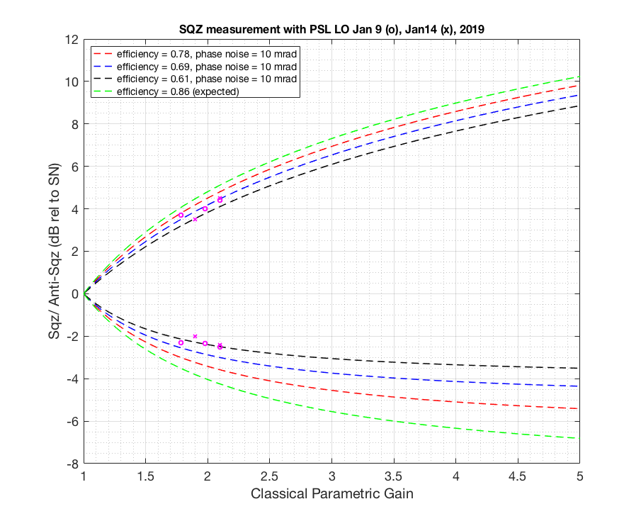
Previously in alog46336 I felt like I was bottomed out on some of the measurements phase delay wise. To get more phase delay so we can be more confident in our measurement I gave 3MHz phase delay box to CLF (I have a feeling that phase delay box hooked up to LO/OMC gives me a bit less phase, not sure if that make sense, I will post more detail alog on the ellipse rotation later). Add CLF sign flip on top of that (which gives us extra 90 degree as Daniel suggested) I was able to go from OK to GOOD then back to OKAY measurement on both squeezing and anti squeezing. Flipping LO sign didn't help (180 deg). And using Q error signal to lock the CLF seems to have given me some extra phase adjustment (not sure why, CLF common mode board input 2 now has Q error signal goes into it). This way I know that I've seen the best sqz/asqz (by monitoring LO Q error signal go up and down while adjusting the phase, we locked with I).
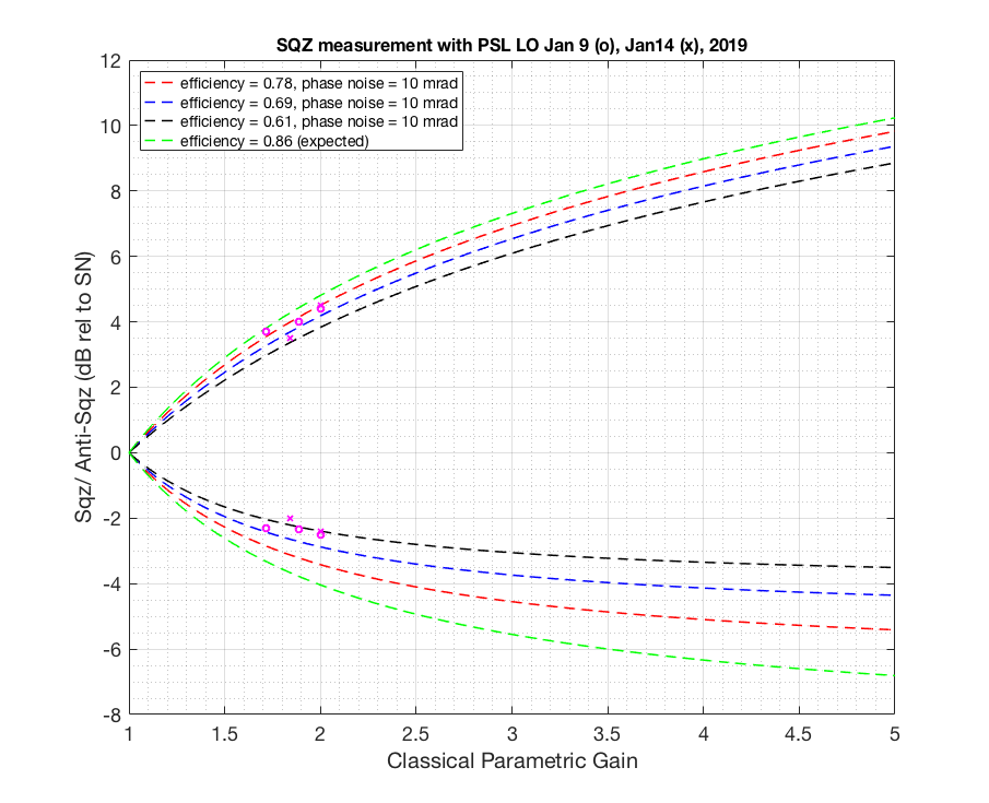
After correcting for some of the minor loss typos and added data taken yesterday after I've acquired more phase delay, here I attached another loss estimate plot. I also give phase noise of 10 mrad this time since assuming that what we measured out of the LO IMON isn't all the phase noise there is. The result hasn't changed. We have more loss compared to when Haocun took a measurement here. We are still in the process of checking red transmission then and now.
Fringe visibility during Jan14 measurement was 99%. In the model I use 97%.

Before the measurement our laser was running multimode again. To get away from multimode I moved the current knob from 2.193A to 2.207A. Temperature stays the same (29.65C). This gives 158MHz without having to put a lot of offset to the control loop (ended up with -7MHz).
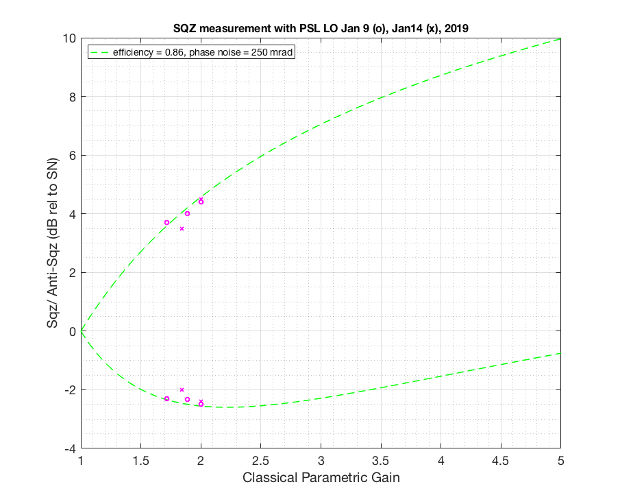
I went back to double check if my nlg was correct and found that the dark noise was actually negative (I missed a minus sign when I subtracted the DN). So here attached a revised plot. That didn't change the result (sadly). I also attached a plot projecting how much phase noise would you need in order to explain what we observe if we were to let efficiency by 86%. You need at least >250 mrad to explain what we have (which is not what we observed in LO error signal).


In order to minimize the transients when switching the second loop ISS on, the following parameters were changed:
| Parameter | New | Old |
|---|---|---|
| H1:PSL-ISS_SECONDLOOP_PD_CAL_GAIN | 1.0 | 1.2 |
| H1:PSL-ISS_SECONDLOOP_AC_COUPLING_DRIVE_OFFSET | 0.0 | 40.0 |
| H1:PSL-ISS_SECONDLOOP_AC_COUPLING_DRIVE_TRAMP | 0 | 3 |
| H1:PSL-ISS_THIRDLOOP_OUTPUT_OFFSET | 540 | — |
| H1:PSL-ISS_SECONDLOOP_AC_COUPLING_INT_BIAS | 240 | 175 |
| H1:PSL-ISS_SECONDLOOP_AC_COUPLING_OFFSET | –5 | +2 |
Furthermore, the gain of the cts2W section in the H1:PSL-ISS_SECONDLOOP_PD_CAL filter module was changed from 0.00155 to 0.001018. This calibrates the in-loop ISS PD array to the same power as the input to the IMC.
The attached plot shows how how the AOM diffraction power reacts when the second loop ISS is turned on and when the input power is changed from 2W to 30W.
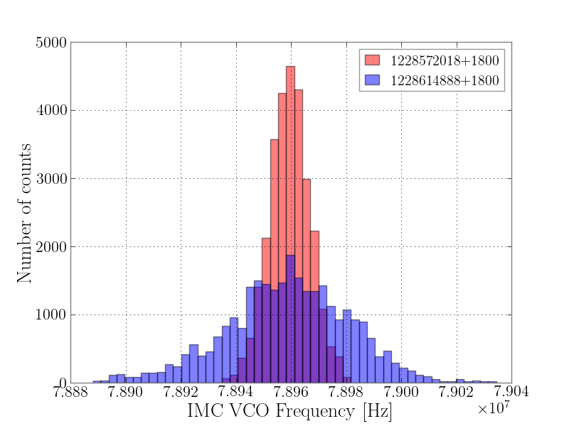
A few days ago I reported in an alog that whistles were back. We really only started to notice them at the end of last week when they became really evident, see for example this plot from the summary pages and all those high frequency, low SNR glitches! I've been looking to see when they first started. I can find whistles after the ifo was recovered from Tuesday maintenance on the 11th December, but not before. I plotted the IMC VCO frequency range in the last lock on Tuesday 11th December and the first lock after recovery; the results can be seen in the first attached plot. Before the ifo was recovered, the IMC VCO frequency range spanned ~78.94 - 78.98 MHz, whereas afterward the range spans ~78.90 - 79.02 MHz. This new range has persisted for the last month. I reattach the likely troublesome frequencies which produce whistles when something beats with the IMC VCO. So it looks like when the IMC VCO range expanded, and covered ~78.91 and ~78.99 MHz, we see whistles.
Yesterday Craig asked if there were any recent spectral measurements of the FSS mixer output - there weren't any.
This morning I set out to do the measurements.
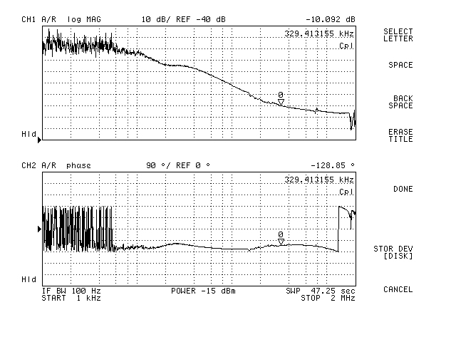
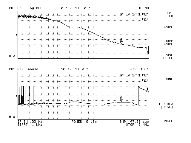
With the input modecleaner locked, a transfer function measurement was made (CG20FG9.jpg, data file has .txt
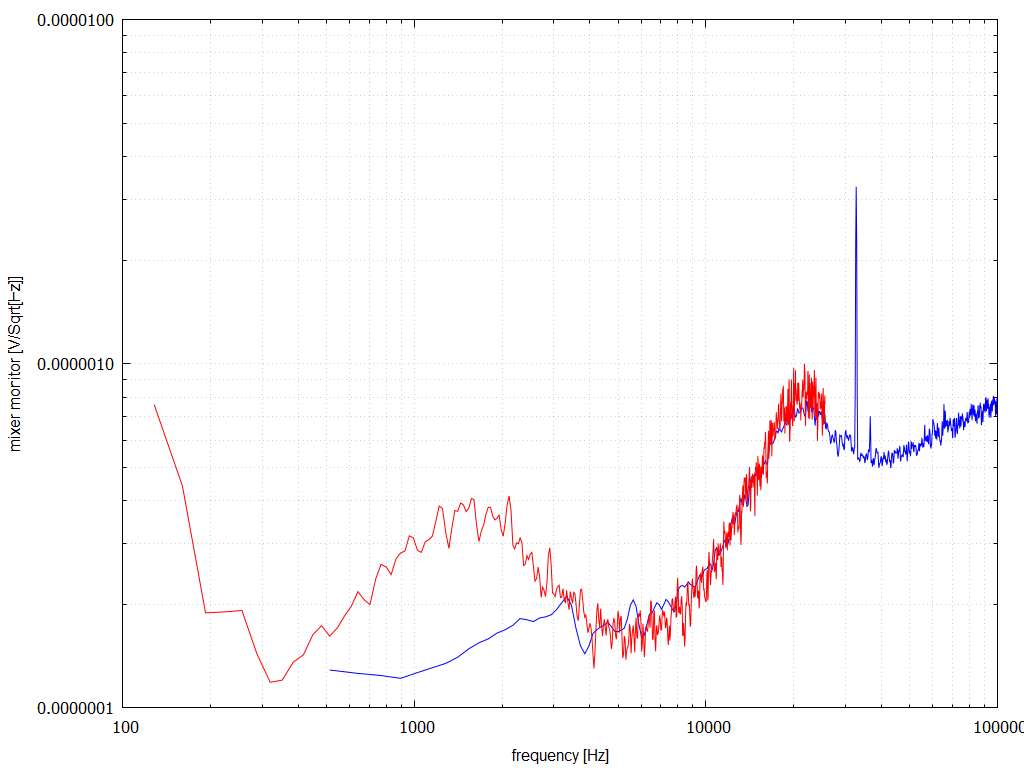
extension). There was nothing unusual with the measurement. A noise measurement was made (mxr.png, data files
are mxr0?.txt). Whilst the measurement was done the spectrum was moving as if a sweep was being done, even though
the network analyser was physically disconnected (see DSCN0648.MOV). I had noticed that the IMC MEDM screen
flashed the message that the IMC WFS were not centred. Even with the IMC in the down state this behaviour did not
stop.
Not long afterwards I noticed at the PZT monitor strip chart on the FSS MEDM screen was wall to wall black
and that reducing the common gain had no effect. The mixer monitor signal was constantly greater than 1.2 Vpp.
I then remembered that work was being done on HAM2 and thought what I was seeing might be related. However when
that work was completed, the behaviour remained. I then noticed that the metal block over the PA85 was stone cold,
whereas it is normally warm to the touch. A quick check of its output voltage indicated that it was almost always
close to zero suggesting a blown PA85.
The spare FSS was deployed. It locked readily enough, however for unknown reasons the common gain could not be
increased much beyond -6 dB without the PZT railing. Clearly there is some difference between the two units,
although I seem to remember bringing them to the same hardware level 4 years ago. The PA85 was replaced in the
original FSS, and things locked up straight away. The PZT was not oscillating, gain sliders were restored. The
transfer function with the repaired FSS is in PA85.jpg (data file PA85.txt).
It was there I left things, since the input modecleaner needed to be back online by 08:30 am local.
It is not obvious why the PA85 died. One possible reason is due to overheating. With the FSS located under
the PSL table not as much air gets blown over the PCB. With the lid off the FSS box, the conducting surface area
is reduced somewhat. Unfortunately accessing the test points requires removing the lid.
Peter / Richard / Ed
For future reference, the trans PDC FSS-TPC_DC was at around 3.1-3Volts when this was taken.
WP#8036
Swapped out leaky TCSY Chiller #2 with our spare (Chiller #3). Last week T.Vo and I had issues getting the spare to start up (alog46292), but after testing it in a closed system later in the week, I found no problems. Today it fired right up without issue as well.
Note for resetting the R323: Go to: Menu --> Settings --> Serial Comm (scroll way down past the gaps) --> Select the R323.
I replaced the two HV power supplies that I had previously placed on the floor in the squeezer rack to power the temporary TTFSS chassis on ISCT6 as Richard wanted these supplies for EX, PEM noise investigation. The supplies are programmed for 180VDC (+/-). The power cables from both 18V and 180V are connected to the chassis. 18V power is on. HV is OFF.
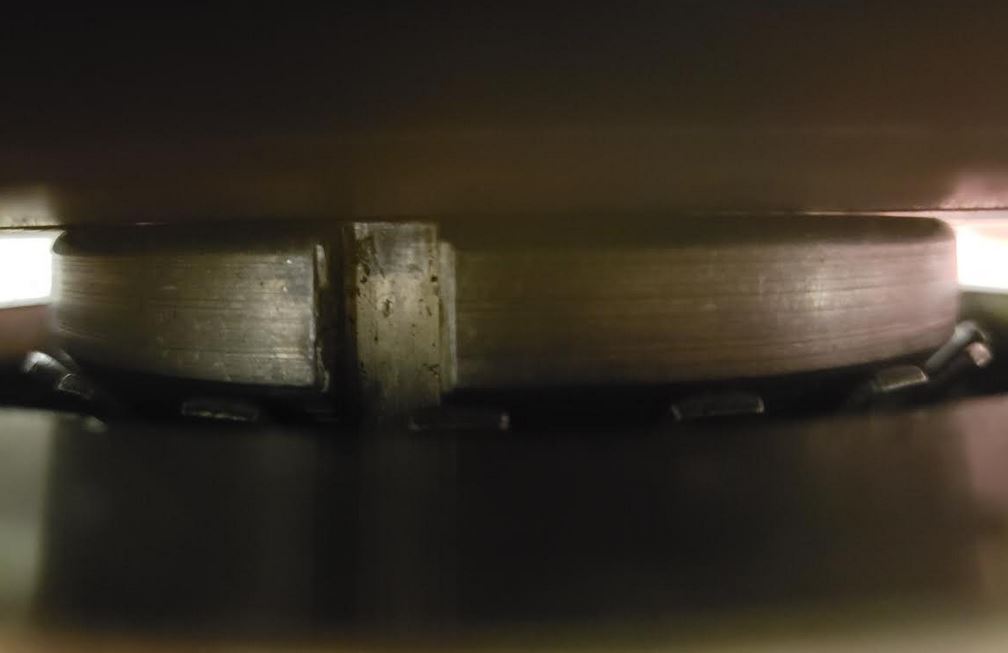
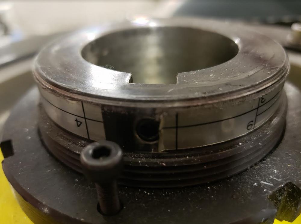
Visually inspected GV4 and found it is equipped with a retaining nut and anti-rotation locking washer. Torque setting on pulley nut as seen in attached photo.
Again I tapped on HAM 7 annulus ion pump but the red overload light remained on, so I turned off the power supply.
TITLE: 01/15 Day Shift: 16:00-00:00 UTC (08:00-16:00 PST), all times posted in UTC
STATE of H1: Commissioning
OUTGOING OPERATOR: None
CURRENT ENVIRONMENT:
Wind: 7mph Gusts, 4mph 5min avg
Primary useism: 0.04 μm/s
Secondary useism: 0.29 μm/s
QUICK SUMMARY:
The LVEA has transitioned to LASER SAFE.
This is under work permit #8048.
Sheila, Georgia, Craig, Koji
We changed the ETMX ESD bias back to 430 V, because we have been having many of the glitches that saturate the ESD drive, and also some locklosses where we were running out of range on the ETMX ESD. Before this change the RMS was approaching 2e4 counts (we have a 20 bit DAC), but now it is about 1e5. This is undoing the change in 45193
After this change we went to the calibration measurement guardian state and started actuation sweeps. They have been saved in the calibration SVN.
I've exported and committed the above mentioned actuator sweep measurements. Thanks all!!
The files live here:
/ligo/svncommon/CalSVN/aligocalibration/trunk/Runs/O3/H1/Measurements/FullIFOActuationTFs/
2019-01-14_H1SUSETMX_L1_iEXC2DARM_25min.xml
2019-01-14_H1SUSETMX_L1_PCAL2DARM_8min.xml
2019-01-14_H1SUSETMX_L2_iEXC2DARM_17min.xml
2019-01-14_H1SUSETMX_L2_PCAL2DARM_8min.xml
2019-01-14_H1SUSETMX_L3_iEXC2DARM_8min.xml
2019-01-14_H1SUSETMX_L3_PCAL2DARM_8min.xml
I've opened FRS12139 to cover this.
Greg will first upgrade h1hwinj1 to SL7.6 before we install/configure monit and its web interface.