Displaying reports 44121-44140 of 88572.Go to page Start 2203 2204 2205 2206 2207 2208 2209 2210 2211 End
Reports until 19:32, Sunday 09 December 2018
H1 SQZ
sheila.dwyer@LIGO.ORG - posted 19:32, Sunday 09 December 2018 (45789)
seeding on CLF measurement

Terry and I quickly set up a 1811 on the CLF beam to check for seeding, and we see that our level of 3MHz sidebands on the CLF (which will be at the interferomter carrier frequency) is similar to what was seen at LLO 37945

Details:

We put the 1811 (AC coupled version) in place of the CLF rejected diode.  We used the half wave plate in front of the PBS to reduce the power here.  Once the diode was in we set the waveplate so that we saw 495 +/- 5mV of DC output (transimpedance 10V/mA) and measured the RF (+/- 1dBm for all):

-75dBm at 3.127 MHz
-75dBm at 200 MHz
-75.8 dBm 203.128 MHz  

Comparing this to LLO, we are getting 4 times more DC power, and about 6dBm more 3MHz signal, so that means that relative to the carrier our seeding power level is similar to LLO.  We haven't moved the RF amplifiers, feedthroughs, or attentuators as was done at LLO, which is consistent with the LLO results.  

While we were doing this measurement, I must have bumped the PBS in the CLF path which is very loose in it's mount, misalinging the fiber input  Terry tightened the mount, and we were able to find the beam in reflection off the OPO by carefully adjusting the PBS mount.  Then we used the two steering mirrors in front of the fiber coupler to maximize the transmission.  We found while doing this that the CLF launch diode was misaligned, and it looks like this has been misaligned for more than 20 days.  The beam is now aligned onto the diode.  Terry measured 4mW going towards the fiber, and the fiber launch diode reports 3.75mW towards the fiber.  The CLF Trigger diode reports 1 mW coming out of the chamber.  

H1 ISC
stefan.ballmer@LIGO.ORG - posted 13:40, Sunday 09 December 2018 (45786)
ISS re-AC coupling (after running in DC coupling) should be working now

I debugged the ISS_AC_COUPLED state with the IMC only. It seems to be doing what it promises now, but we haven't tried it in full lock. It required quite the dance for making sure the two AC coupling loops don't fight each other.

It is in SVN. Below is source code.


class ISS_AC_COUPLED(GuardState):
    index=58
    request =True

    @ISC_library.assert_dof_locked_gen(['IMC'])
    @ISC_library.gen_check_WFS_DC(['IMC'])
    @ISC_library.iss_checker
    def main(self):
        ezca['PSL-ISS_SECONDLOOP_AC_COUPLING_SERVO_TRAMP'] = 0
        # make sure 3rd loop is off
        ezca['PSL-ISS_THIRDLOOP_SERVO_GAIN'] = 0
        # turn off boosts
        ezca.write('PSL-ISS_SECONDLOOP_BOOST_2',0)
        time.sleep(0.1)
        ezca.write('PSL-ISS_SECONDLOOP_BOOST_1',0)
        time.sleep(0.1)
        # set the AC coupling gain to 0
        ezca['PSL-ISS_SECONDLOOP_AC_COUPLING_SERVO_GAIN'] = 0
        ezca['PSL-ISS_SECONDLOOP_AC_COUPLING_INT_OFFSET'] = 0
        # turn on 1Hz AC couplinf of AC coupling to deal with offset
        ezca.switch('PSL-ISS_SECONDLOOP_AC_COUPLING_SERVO', 'FM6', 'ON')
        # smoothly relief the Reference Integrator
        ezca['PSL-ISS_SECONDLOOP_REFERENCE_SERVO_OFFSET'] = 0
        ezca.switch('PSL-ISS_SECONDLOOP_REFERENCE_SERVO', 'INPUT', 'OFF')
        self.timer['pause'] = 15
        self.counter = 0

    @ISC_library.assert_dof_locked_gen(['IMC'])
    @ISC_library.gen_check_WFS_DC(['IMC'])
    @ISC_library.iss_checker
    def run(self):
        # run the fault check function, which prints fault
        # notificaitons, but don't do anything since we don't want to
        # break lock unnecessarily.
        ISC_library.PSL_ready()

        if self.counter == 0 and self.timer['pause']:
            # set up TRAMP for AC coupling
            ezca['PSL-ISS_SECONDLOOP_AC_COUPLING_SERVO_TRAMP'] = 3
            # turn on INPUT coupling to initialize the AC coupling FM6
            ezca.switch('PSL-ISS_SECONDLOOP_AC_COUPLING_SERVO', 'INPUT', 'ON')
            # and start the servo for the OFFSET and reference integrator
            ezca['PSL-ISS_SECONDLOOP_AC_COUPLING_INT_OFSEN'] = 1
            ezca.switch('PSL-ISS_SECONDLOOP_REFERENCE_SERVO', 'OFFSET', 'ON')
            self.timer['pause'] = 10
            self.counter += 1
        if self.counter == 1:
            ezca['PSL-ISS_SECONDLOOP_AC_COUPLING_INT_OFFSET']=(ezca['PSL-ISS_SECONDLOOP_AC_COUPLING_DRIVE_OUT16'] - ezca['PSL-ISS_SECONDLOOP_AC_COUPLING_OUTPUT'])/5000.0
            ezca['PSL-ISS_SECONDLOOP_REFERENCE_SERVO_OFFSET']=(ezca['PSL-ISS_SECONDLOOP_REFERENCE_SERVO_OUTPUT'] )/100000.0
            if abs(ezca['PSL-ISS_SECONDLOOP_AC_COUPLING_DRIVE_OUT16'] - ezca['PSL-ISS_SECONDLOOP_AC_COUPLING_DRIVE_INMON']) < 1.0:
                if abs(ezca['PSL-ISS_SECONDLOOP_REFERENCE_SERVO_OUTPUT']) < 1e-3:
                    ezca.switch('PSL-ISS_SECONDLOOP_AC_COUPLING_DRIVE', 'HOLD', 'OFF')
                    ezca['PSL-ISS_SECONDLOOP_AC_COUPLING_INT_OFSEN'] = 0
                    ezca['PSL-ISS_SECONDLOOP_AC_COUPLING_INT_OFFSET'] = 0
                    ezca.switch('PSL-ISS_SECONDLOOP_REFERENCE_SERVO', 'OFFSET', 'OFF')
                    ezca['PSL-ISS_SECONDLOOP_REFERENCE_SERVO_OFFSET'] = 0
                    self.counter += 1
        if self.counter == 2 and self.timer['pause']:           
            ezca['PSL-ISS_SECONDLOOP_AC_COUPLING_SERVO_GAIN'] = -0.3
            self.timer['pause'] = ezca['PSL-ISS_SECONDLOOP_AC_COUPLING_SERVO_TRAMP'] + 3
            self.counter += 1
        if self.counter == 3 and self.timer['pause']: 
            ezca.switch('PSL-ISS_SECONDLOOP_AC_COUPLING_SERVO', 'FM6', 'OFF')
            self.timer['pause'] = 20
            self.counter += 1
        if self.counter == 4 and self.timer['pause']:
            ezca.switch('PSL-ISS_SECONDLOOP_REFERENCE_SERVO', 'INPUT', 'ON')
            self.counter += 1
        if self.counter == 5: 
                return True
 

H1 ISC
stefan.ballmer@LIGO.ORG - posted 21:42, Saturday 08 December 2018 - last comment - 13:31, Monday 10 December 2018(45782)
H1 joins the Holiday Party

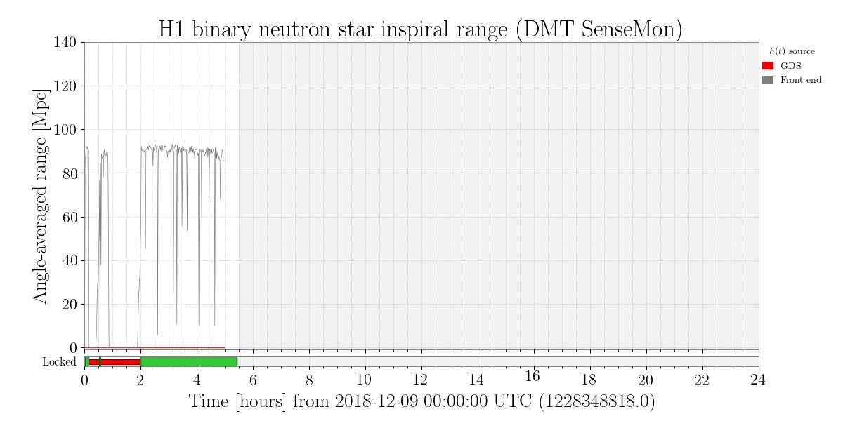
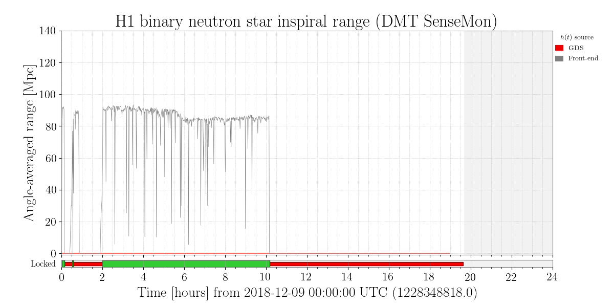
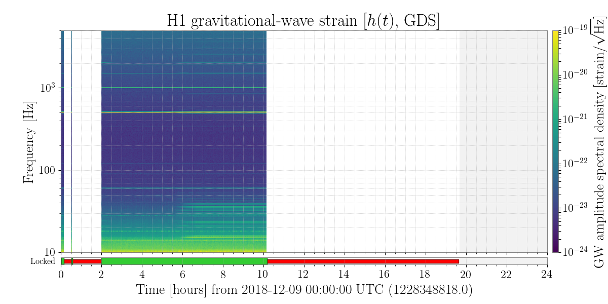
Since everybody went to the holiday party tonight, I left the interferometer in low noise. After guardian was done, I punched up the input power to 25W (without reducing the DARM offset, i.e. letting the OMC current grow to 25mA), and then increased the DARM offset by another 9% (~30mA). Finally, I blindly increased the SRCLFF by 9% (punching in 1.09 in the gain), and left it there.

Looks like the machine sat there stably at 90Mpc for the whole holiday party... Merry Christmas!

Images attached to this report
Comments related to this report
andrew.lundgren@LIGO.ORG - 13:31, Monday 10 December 2018 (45816)DetChar, ISC, SUS
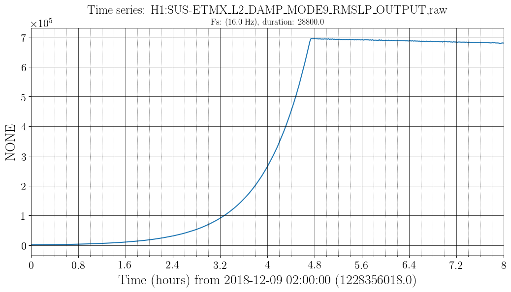
The period of bad data looks to be due to a ringup of a violin mode fundamental at 516.78 Hz (ETMX mode 9). It goes up in amplitude by a factor of ~60 and becomes the largest signal on the DCPD.

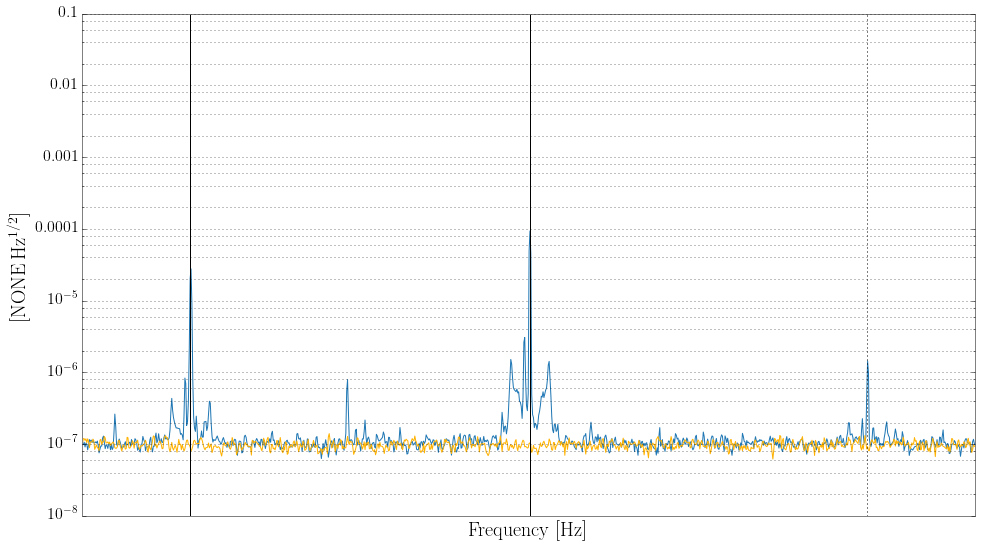
Once the mode becomes large enough, some nonlinearity makes a forest of lines at low frequencies, and multiples of the violin mode show up throughout the spectrum (plus an associated forest of lines). There are also lines 6.07 Hz above and below each multiple, which I think are caused by beating against 510.71 Hz. This is ETMY mode 1 according to MEDM, and it's also high but not growing during the lock.

The nonlinearity becomes a problem around 5:50 UTC, when the violin mode monitor goes above 2e5 counts, see first plot. A spectrum around the line at 3*516.78 Hz is the second plot, with the lines at 6.07 Hz above and below also marked.

These violin modes and their ID are given in alog 43661, though the 510 Hz line since seems to have been identified as ETMY rather than ETMX.
Images attached to this comment
gabriele.vajente@LIGO.ORG - 12:05, Sunday 09 December 2018 (45785)

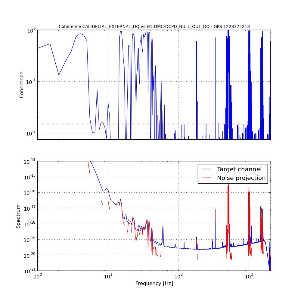
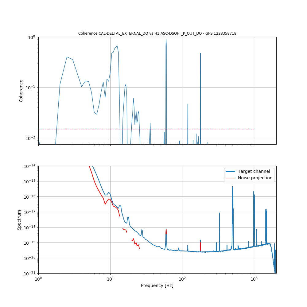
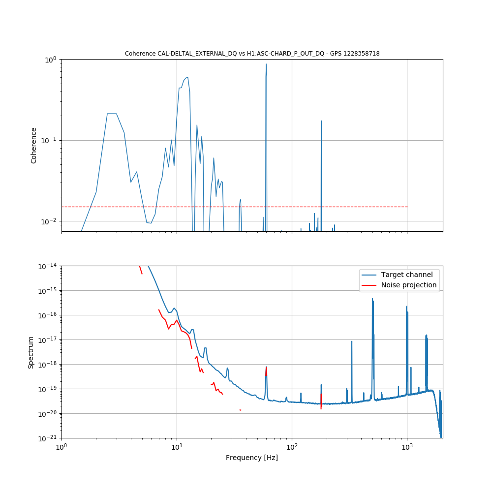
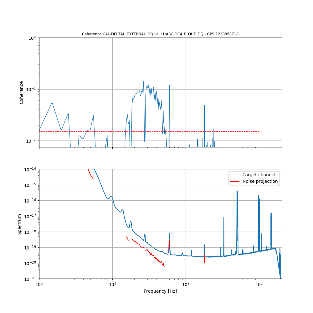
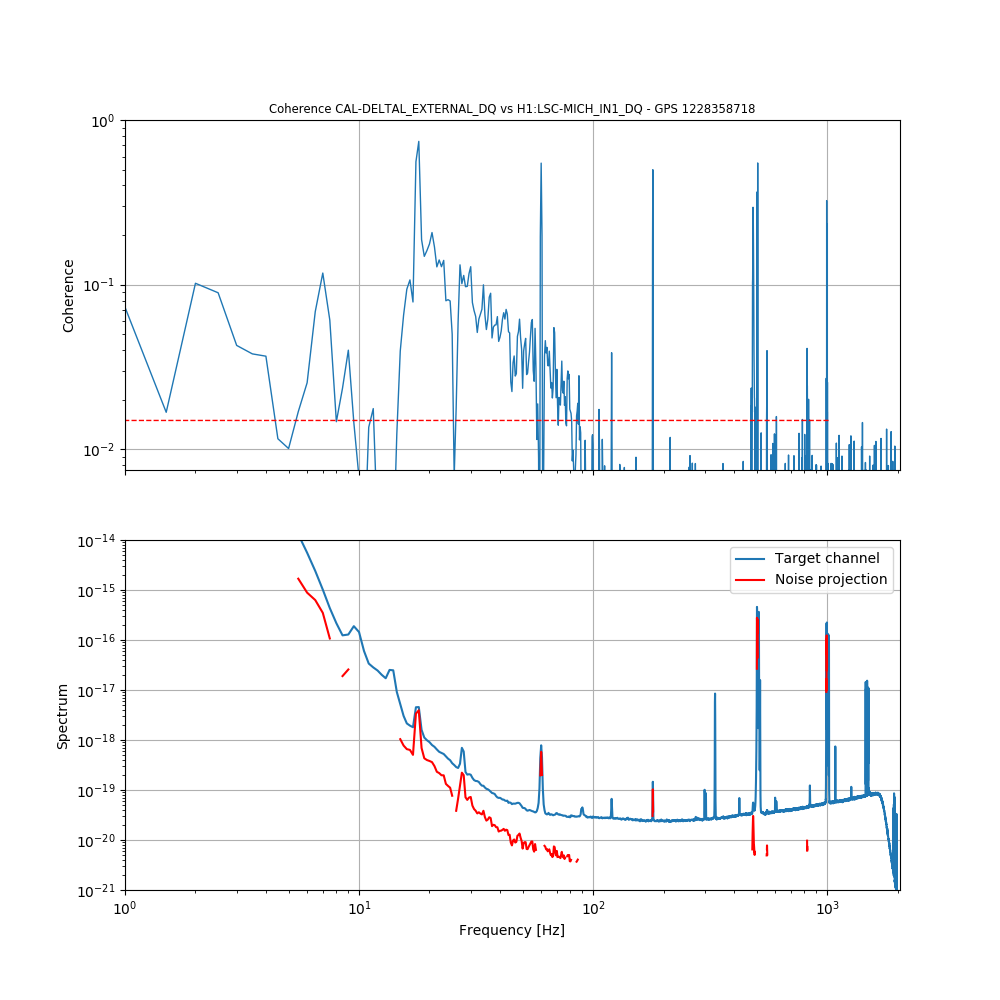
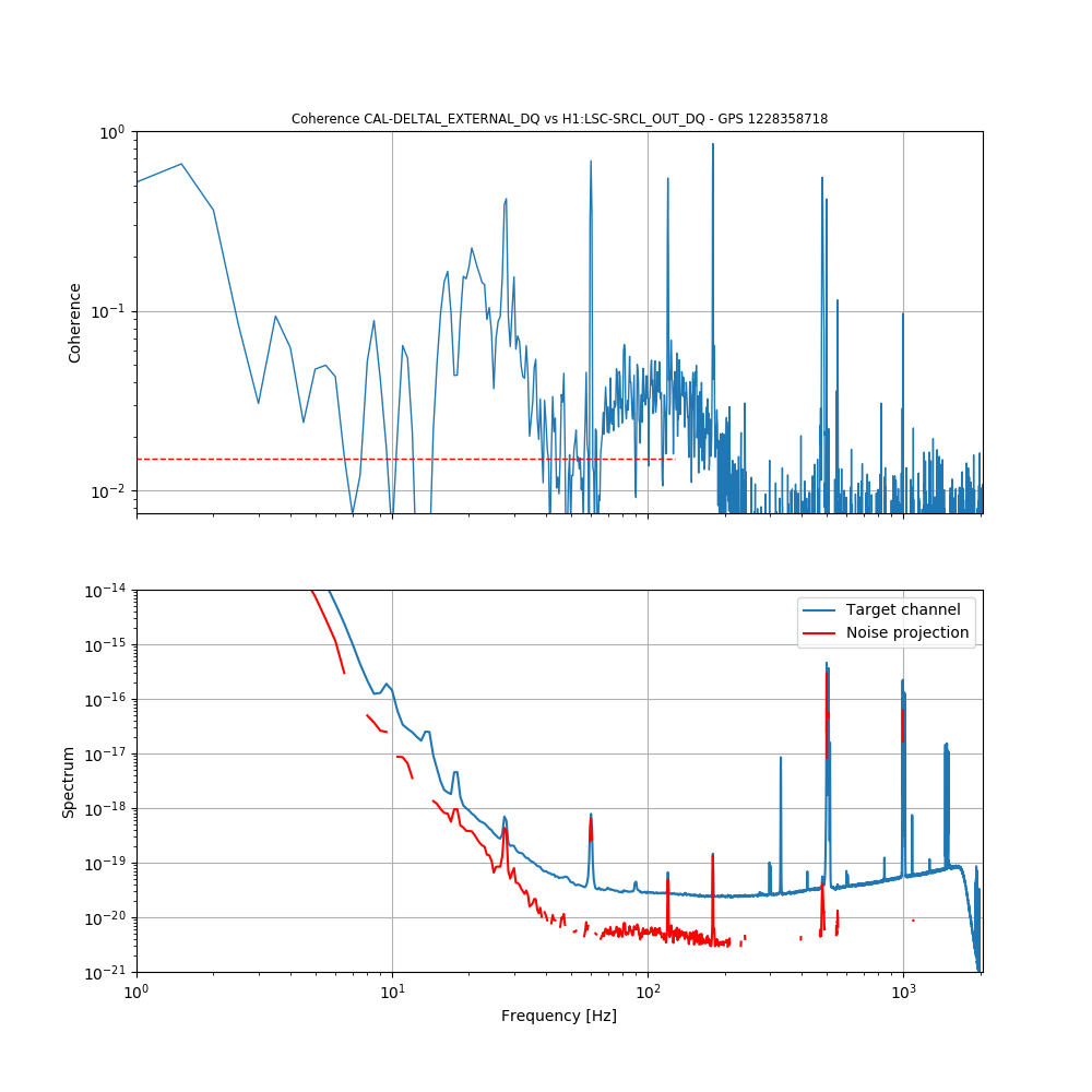
At around 6:00 UTC the range started to decline, it seems due to some noise in the form of a family of peaks below 40 Hz.

I ran two BruCo scans for a time before and after the change in noise.

Before: https://ldas-jobs.ligo.caltech.edu/~gabriele.vajente/bruco_lho_1228358718/

After: https://ldas-jobs.ligo.caltech.edu/~gabriele.vajente/bruco_lho_1228372218/

The most interesting thing I can see right now is that the peaks are coherent with the NULL stream.

Looking at coherences before the range worsening:

  • Low frequency (below 20 Hz) ASC (DSOFT_P and CHARD_P)
  • Between 15 and 40 Hz there is coherence with the centering loop DC4_P 
  • Coherence with MICH and SRCL is significant up to 200 Hz


Images attached to this comment
LHO VE
kyle.ryan@LIGO.ORG - posted 18:01, Saturday 08 December 2018 (45781)
AIP at X-mid went offscale today

Normally (assuming a failed component), we would fix this on a Tuesday maintenance day.  Although, this week, we might be too pre-occupied with the Pfeiffer pump systems installation/demonstration at Y-mid to get to it(?) 

H1 ISC (ISC)
hang.yu@LIGO.ORG - posted 17:43, Saturday 08 December 2018 - last comment - 10:07, Monday 10 December 2018(45779)
Locklosses after ~15 mins at 28 W

Stefan, TVo, Hang

We were able to power up to 28 W and stay there stably for about 15 mins or so. However, after that we still had two kinds of locklosses.

=======================================

In the first time we lost lock when POP18 dropped to 50 and then a fast lock loss. Since we had re-distributed the gains in the common mode board (as powering up, in stead of dropping gains at the very end using IMC-REFL_SERVO_FASTGAIN, we decreased the gain upstream in LSC-REFL_SUM_A_IN2GAIN), this thus ruled out that saturation inside the common mode board was the cause for the fast lock losses. More investigation needed.

Also we noticed that at 20 W the LSC-REFL_A_RF9_Q was very close to zero, meaning a good balance of the upper and lower sidebands, while as we powering up, the REFL_9_Q increased by a lot.

=======================================

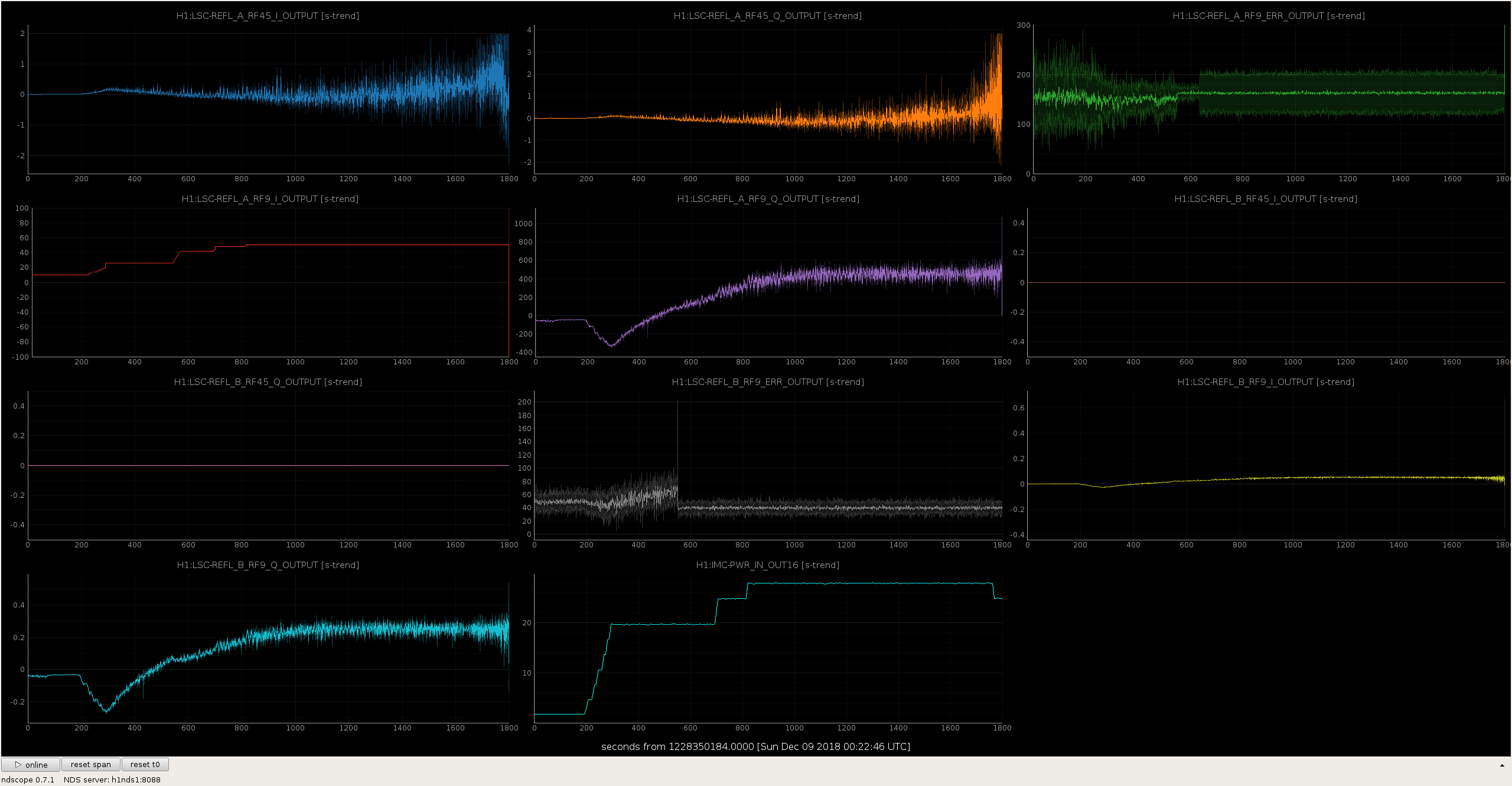
In the second time, still after about 15 mins at 28 W, an oscillation at 0.4 Hz grew in CHARD YAW ASC. This might be related to the CHARD blending (for yaw, DC part from REFL 9 and AC part from TR QPD combo) which was designed to happen at 0.4 Hz. As we kept losing optical response in the REFL9 signal, this might then lead to an instability in the signal blending. This hypothesis is also consistent with the fact that we did not see similar behavior in CHARD PITCH, as we changed the input matrix for CHARD PIT DC path to REFL45 (LHO:43633) which decayed much less then the RF9 signal and therefor the pitch stayed stable. The solution might thus be either changing the CHARD YAW to using REFL 45 like we did for pitch, or monitoring the signal strength in both REFL9 and QPD combo to keep their ratio constant, or (for a single lock) servo CHARD YAW only to QPD combos as a quick test.

Comments related to this report
stefan.ballmer@LIGO.ORG - 17:45, Saturday 08 December 2018 (45780)

Here is a plot of what LSC REFL does when going to 30W. THe growth in the final 50 seconds corresponds to the 0.4Hz instability.

Images attached to this comment
thomas.vo@LIGO.ORG - 10:07, Monday 10 December 2018 (45811)

We also tried a common lens adjusted on the CO2 lasers to try and re-gain some POP18 build up but we couldn't get back much (about 2 counts) compared to the drop from about 70 to 55 counts.  Two caveats though, we only waited about 5 minutes before moving on so maybe it would have gotten better and also the REFL9_Q_ERR seems to get noisier going from 20 watts to 25 watts which could get better with differential lens tuning.

H1 ISC
stefan.ballmer@LIGO.ORG - posted 16:30, Saturday 08 December 2018 - last comment - 17:32, Tuesday 18 December 2018(45777)
IMC_power_adjust_func() updated to enable ramping down input sliders

Hang, TVo, Stefan,

Worrying abut high frequency saturation in the CARM servo (https://alog.ligo-wa.caltech.edu/aLOG/index.php?callRep=45768), we updated the IMC_power_adjust_func() in ISC_library.py to start scaling down the input sliders instead of the output sliders.

Specifically, if IMC-REFL_SERVO_FASTGAIN drops below a certain threshold (FG_THRESH), instead of adjusting IMC-REFL_SERVO_FASTGAIN and LSC-MCL_GAIN, we switch to adjusting IMC-REFL_SERVO_IN1GAIN and LSC-REFL_SUM_A_IN2GAIN.

Since we start off with IMC-REFL_SERVO_FASTGAIN = 0 dB at 2W, FG_THRESH=-20 corresponds to 20W, and would leave everything the same up to 20W.


For now we left FG_THRESH at -10dB (6.3W) to give us an extre factor of 3 saturation headroom.

Below is the source code (in ISC_library.py), which is checked into SVN.


We tested the script for functionality and went to 28W for 15min (92Mpc), but then still lost lock. More work to be done.


#################################################
# check input power
#################################################
def IMC_power_adjust_func():
    # at 2.0 Watts input power the nominal gain on IMC Fast Gain should be 0 dB
    calc_gain = 20.0*math.log10(2.0/ezca['IMC-PWR_IN_OUTMON']) 
    calc_gain = min(calc_gain, 31)

    # it only changes the power if there is a difference of 1 dB.  
    # This is intended to prevent repeated 1 dB gain changes
    #  if we are on the edge between two gain settings with the input power. 
    FG_THRESH=-10    # was -20
    IMC_NOM  = 28
    CMB_NOM  =  8
    PWR_MIN  =  4.0

    if ezca['IMC-PWR_IN_OUTMON'] < PWR_MIN:
        # use old logic - ignore the input sliders
        # this is to avoid interfering with the common mode engage sequence
        diff_gain = calc_gain - ezca['IMC-REFL_SERVO_FASTGAIN']

        if abs(diff_gain) >= 1:
            R_diff_gain=round(diff_gain)
            log('power_adjust is changing IMC Common Mode Board IN1 gain by a bit...' )
            ezca['IMC-REFL_SERVO_FASTGAIN'] += R_diff_gain

            time.sleep(0.2)
            if abs(ezca['LSC-MCL_GAIN']) > 1e-9:
                ezca['LSC-MCL_GAIN'] *= 10**(R_diff_gain/20.0)

            elif abs(ezca['IMC-MCL_GAIN']) > 1e-9:
                ezca['IMC-MCL_GAIN'] *= 10**(R_diff_gain/20.0)
    else:
        # use new logic - incorporate input sliders, start lowering input sliders once IMC-REFL_SERVO_FASTGAIN falls below FG_THRESH
        diff_gain_old = calc_gain - ezca['IMC-REFL_SERVO_FASTGAIN']
        diff_gain = calc_gain - ezca['IMC-REFL_SERVO_FASTGAIN'] + CMB_NOM - ezca['LSC-REFL_SUM_A_IN2GAIN']

        if abs(diff_gain) >= 1:
            R_diff_gain_old=round(diff_gain_old)
            
            if ezca['IMC-REFL_SERVO_FASTGAIN'] + R_diff_gain_old >= FG_THRESH:            
                log('power_adjust is changing IMC Common Mode Board IN1 gain by a bit...' )
                ezca['IMC-REFL_SERVO_FASTGAIN'] += R_diff_gain_old
                if abs(ezca['LSC-MCL_GAIN']) > 1e-9:
                    ezca['LSC-MCL_GAIN'] *= 10**(R_diff_gain_old/20.0)
                elif abs(ezca['IMC-MCL_GAIN']) > 1e-9:
                    ezca['IMC-MCL_GAIN'] *= 10**(R_diff_gain_old/20.0)
                # and set back the input gains where they need to be
                ezca['IMC-REFL_SERVO_IN1GAIN'] = IMC_NOM
                ezca['LSC-REFL_SUM_A_IN2GAIN'] = CMB_NOM
            else:
                # set the output gains where they need to be
                R_diff_gain = FG_THRESH - ezca['IMC-REFL_SERVO_FASTGAIN']
                if abs(ezca['LSC-MCL_GAIN']) > 1e-9:
                    ezca['LSC-MCL_GAIN'] *= 10**(R_diff_gain/20.0)
                elif abs(ezca['IMC-MCL_GAIN']) > 1e-9:
                    ezca['IMC-MCL_GAIN'] *= 10**(R_diff_gain/20.0)            
                ezca['IMC-REFL_SERVO_FASTGAIN'] =FG_THRESH
                # set the output gains
                diff_gain_new = calc_gain - (FG_THRESH) +CMB_NOM - ezca['LSC-REFL_SUM_A_IN2GAIN']
                R_diff_gain_new = round(diff_gain_new)
                ezca['IMC-REFL_SERVO_IN1GAIN'] += R_diff_gain_new
                ezca['LSC-REFL_SUM_A_IN2GAIN'] += R_diff_gain_new
 

Comments related to this report
sheila.dwyer@LIGO.ORG - 17:32, Tuesday 18 December 2018 (46053)

Craig, Sheila

We have reverted this change, because in the past we had locklosses caused during power up by glitches on the input sliders.  We fixed those locklosses when we changed to instead adjusting the output slider during the power up.  See 44422

We can lower the input gain by changing the gain used in ANALOG_CARM

H1 SQZ (SQZ)
nutsinee.kijbunchoo@LIGO.ORG - posted 11:51, Saturday 08 December 2018 - last comment - 18:15, Sunday 09 December 2018(45774)
SQZ intensity noise at various places

Daniel, Nutsinee

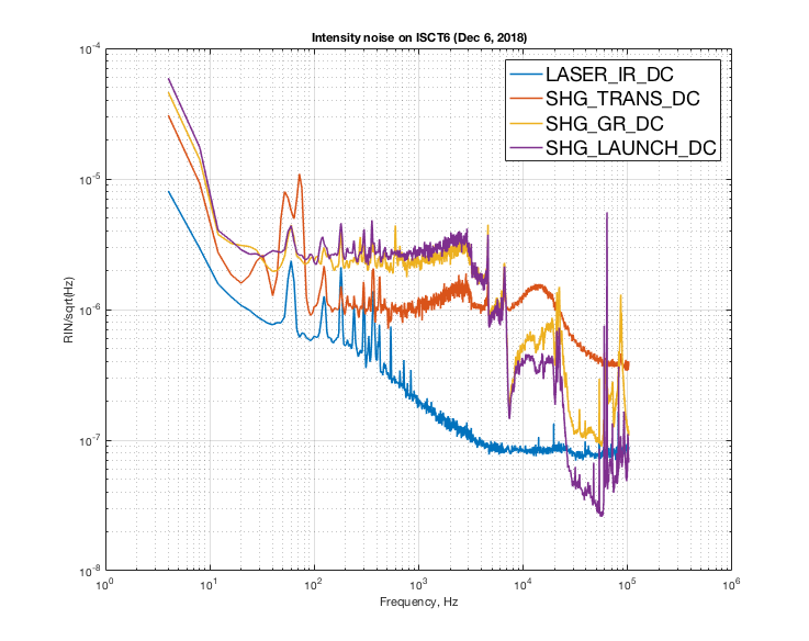
Attached a RIN plot of various detectors on ISCT6 table. The blue plot is the intensity noise measured off the laser monitor diode. By the time we get to SHG trans PD the noise is worsen by a factor of 10 at ~2-3kHz. The factor of two difference between SHG trans (red) and the green PDs is due to red->green conversion. Question is, this is what we saw in the IFO squeezing attempt in alog45767 ?   To be sure that switching scheme helps we need the same intensity noise data from LLO to compare. If LLO intensity noise is not as bad as ours switching scheme may not solve the problem. 


Images attached to this report
Comments related to this report
sheila.dwyer@LIGO.ORG - 18:15, Sunday 09 December 2018 (45787)

Terry, Sheila

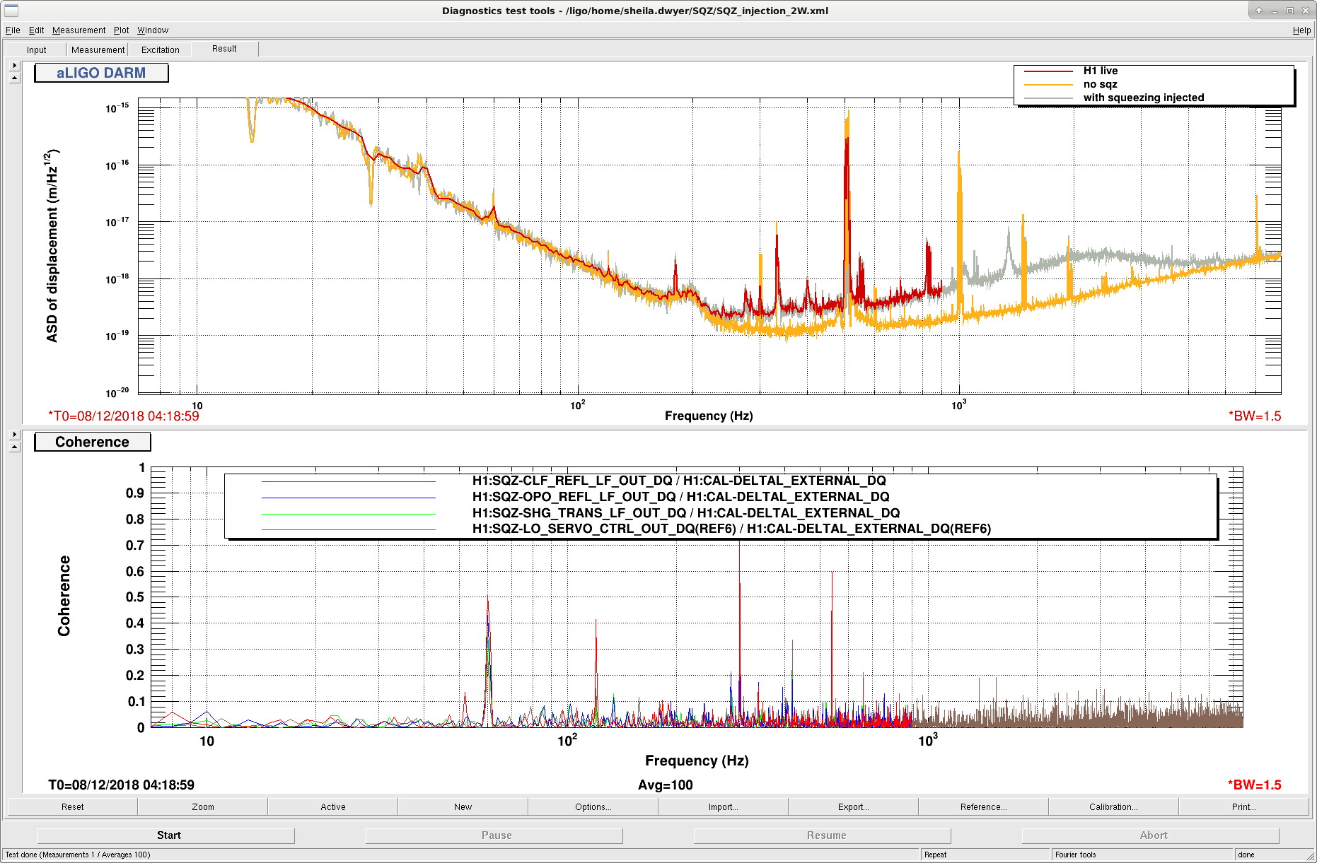
We looked at coherence between DARM when we had injected squeezing on Friday night, with intensity noise on a few of the diodes which are recorded at 2kHz.  (OPO REFL, SHG trans, and CLF refl).  We don't see any coherence with intensity noise and DARM.  

We also looked at the additive offset channel which was used to detune the OPO from resonance, and we don't see any coherence with DARM. 

We wouldn't expect a linear coupling from either of these things to DARM in the first place, unless we have a bad seeding problem, but this was just a check.  We will work on setting up a diode to test for seeding.   


Images attached to this comment
H1 CDS
david.barker@LIGO.ORG - posted 11:46, Saturday 08 December 2018 - last comment - 08:46, Sunday 09 December 2018(45773)
making space on /opt/rtcds

The 1TB SSD raid for the /opt/rtcds file system is at 90% full. 513G of this is in the target_archive area. I'm currently creating compressed tar images of these directories (and then deleting the source). This will take several hours to complete. (these directories compress by a factor of roughly an order of magnitude).

Comments related to this report
david.barker@LIGO.ORG - 08:46, Sunday 09 December 2018 (45783)

Yesterday I compressed most of /opt/rtcds/lho/h1/target_archive. Because we are keeping about a month of hourly ZFS snapshots on h1fs0 (and its backup machine h1fs1) the recovered disk space is not immediately available. To offset the additional space needed for the compressed tar files, I manually deleted ten days of snapshots from 10th - 20th November. As the archived snapshots get rotated out, the disk space used will fall dramatically. At that point I'll compress the remaining targets and extend the lookback to a month again.

LHO VE
kyle.ryan@LIGO.ORG - posted 08:29, Saturday 08 December 2018 - last comment - 09:19, Saturday 08 December 2018(45769)
Y2-8 beamtube ion pump

New problem?  This is showing that it has shut off.  This is very recent and will show up as a pressure increase soon if it is real -> I will monitor and make comment to this entry when data confirms or refutes.

Comments related to this report
chandra.romel@LIGO.ORG - 08:35, Saturday 08 December 2018 (45770)

It could be that the solar PV charged battery that powers that gauge is low due to the cloudy, cold days we've had (we had this issue last year....need more solar! :). I looked at both these pumps yesterday and they were ON. We now have end station IPs valved in so if these BT IPs fail it's not so urgent. Gerardo and I talked about alarming on the voltage of Y2-8 & X2-8 so we know if/when the pump (or HV cable) fails.

kyle.ryan@LIGO.ORG - 09:19, Saturday 08 December 2018 (45771)

 Pressure data indicates that the pump is still pumping and that only the independently-powered CDS read-back is off. 

H1 ISC (ISC)
craig.cahillane@LIGO.ORG - posted 02:14, Saturday 08 December 2018 - last comment - 12:33, Saturday 08 December 2018(45768)
Frequency Noise Injections with Changing DARM offset
Tonight we power up to 20 watts and were locked for 5 hours.

I measured the CARM OLG (UGF ~ 15kHz) and error spectrum from 0.5 Hz to 5 MHz in response to Stefan and Hang looking for CARM saturations. (PDFs 1 and 2)
They may have been correct to worry: the noise is worst at 100 kHz, a full factor of 10 above where it is at 8 kHz, with peaks a factor of 10 above that.  I'll run some RMS calculations later, but high frequency definitely dominates this spectrum.  We'll need to think about the saturation limits of the common mode board, and the kind of signals we are sending through it to control the laser.

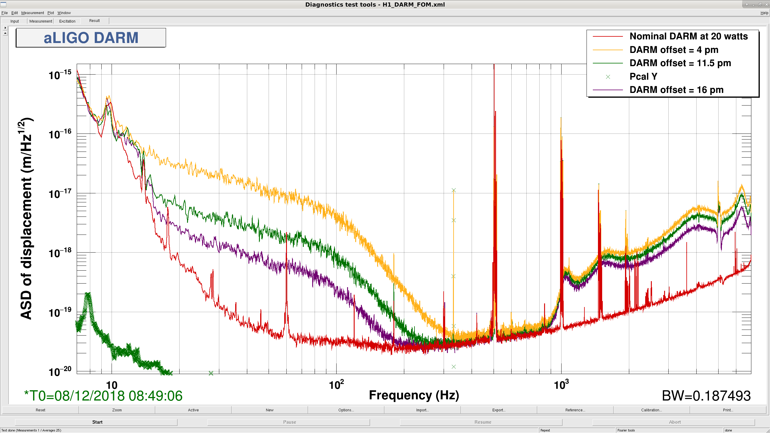
I also ran some bandlimited frequency noise injections with different DARM offsets.  I found that as I reduced the DARM offset, the frequency noise coupling to DARM got worse.  (PNG 1)
This result was counterintuitive to me.  It makes sense for the high frequency noise around 4.1 kHz which masks the OMC dither to cause the low frequency DARM noise to increase with reduced DARM offset, since there is less light in the OMC. But I would have expected the linear Freq to DARM coupling to decrease with reduced DARM offset.  
This prompted me to run a suite of injections which will be analyzed at a later date.
Images attached to this report
Non-image files attached to this report
Comments related to this report
daniel.sigg@LIGO.ORG - 12:33, Saturday 08 December 2018 (45775)

I am particularly puzzled by the scaling. Frequency noise as calculated by T1500461 contains terms that scale linearly with the DARM offset and terms that scale like the third power. The later seems to dominate below a few Hertz. The term that scales linearly would show up as a constant in the sensitivity plot. On the other hand, terms due to higher order modes in the PRC should look like a constant sensing noise, and therefore scale like the inverse of the DARM offset in the sensitivity plot. This scaling at lower frequencies seems roughly inverse if one compares the 4pm and 11.5pm offsets. However, it completely fails to explain the rather significant improvement from 11.5pm to 16pm.

At high frequencies the scaling looks more constant, but this coupling cannot be explained with what's in T1500461 and is thought to be due to higher modes.

H1 SQZ
sheila.dwyer@LIGO.ORG - posted 23:30, Friday 07 December 2018 - last comment - 16:45, Monday 10 December 2018(45767)
squeezer injected into interferometer

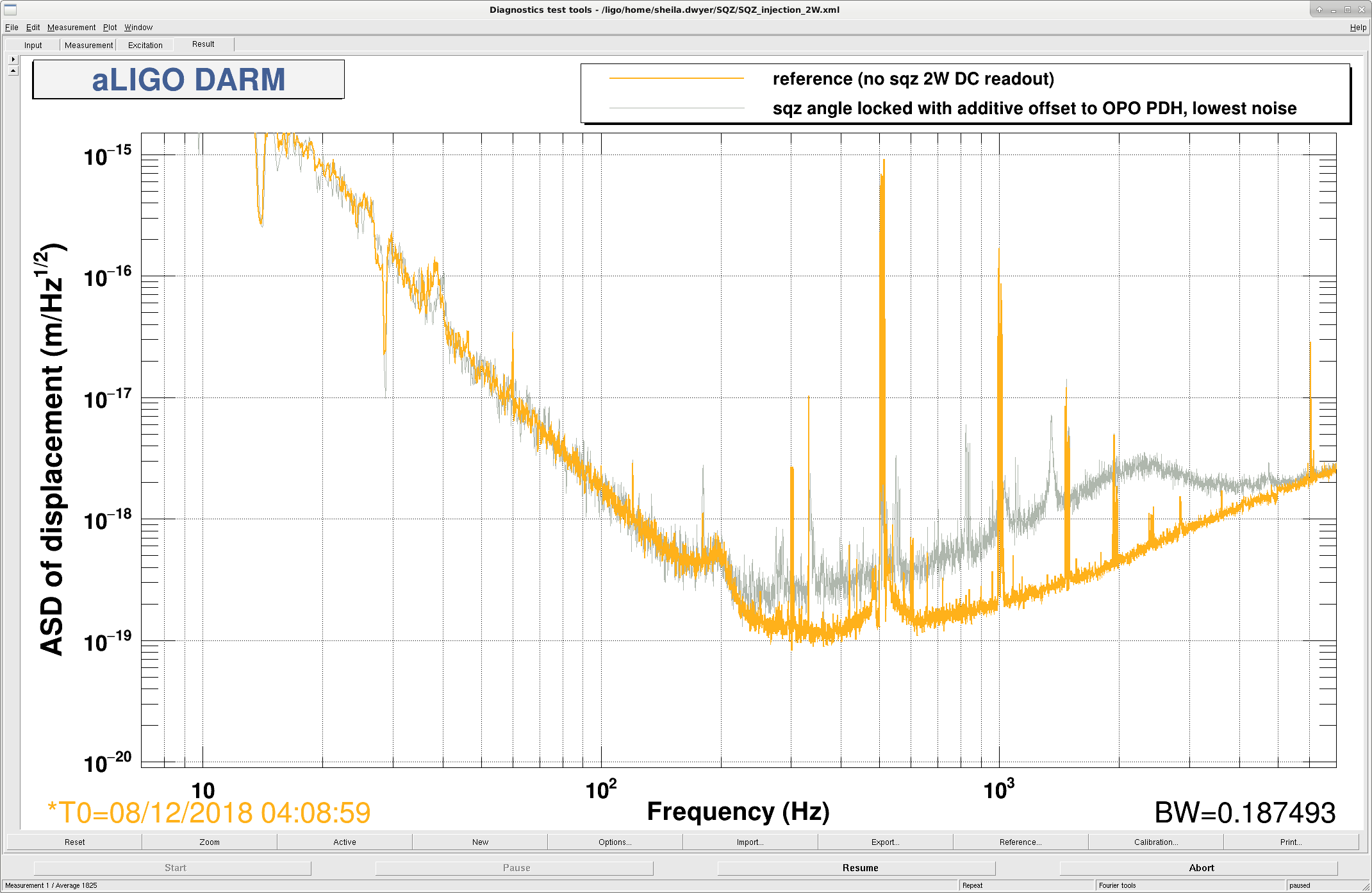
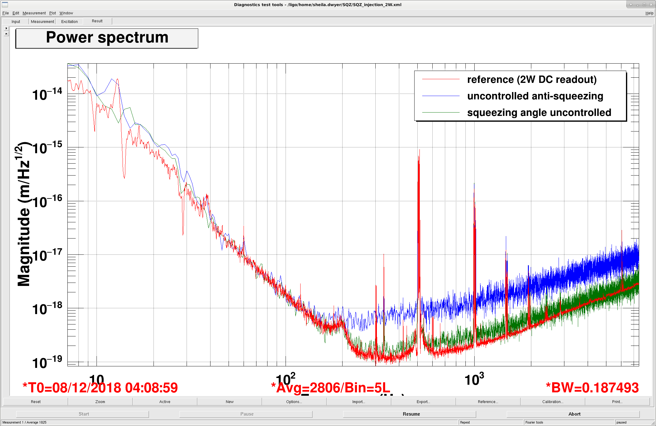
Summary:

We were able to lock the squeezing angle using the 3MHz signal from the OMC DCPD's, and we have caused a few lockloses.  We have found that our locking scheme is introducing a lot of noise, so our next step is to lock the OPO length to the laser frequency.  

Locklosses:

In our first attempt we used the interferometer locked at 2W DC readout to look for the LO error signal.  We caused a lockloss then, and so we then changed to working with the interferometer locked on RF and the OMC locked.  We caused a couple of other locklosses this afternoon, one when the interferometer was locked on RF and the OPO became unlocked with the beam diverter open.  After this we added closing the beam diverter to the OPO guardian DOWN state, and the state CHECK_EOM (which we enter when the TTFSS EOM is railed).  

After successfully locking the squeezer angle, we transitioned to DC readout.  When we attempted to close the beam diverter we lost lock, which we also don't understand.  

We have been injecting ~10uW of CLF (measured on SQZT6), which gives us about 10 dBm of RF on the 3MHz demod.  We are wondering if this is too much and might be part of our lockloss problems.  We tried reducing it by a factor of 2.  

Locking:

Nutsinee will post details of the squeezing angle lock configuration that we used tonight, even though we don't plan to keep using this scheme. 

The basic steps:

Uncontrolled squeezing:

Images attached to this report
Non-image files attached to this report
Comments related to this report
daniel.sigg@LIGO.ORG - 11:39, Saturday 08 December 2018 (45772)

I am not sure what the free-running plot represents. In this case, the 2 lasers differ in frequency by as much as tens of kHz. This would completely invalidate the correlations that are responsible for squeezing. Every now and then the frequencies will cross and one might catch a short glimpse of (anti) squeezing.

The first plot is somewhat of a mystery too. If we really suffer from excess phase noise (as we have measured), why doesn't it effect squeezing at all frequencies? Could it be seeding through the CLF instead?

lisa.barsotti@LIGO.ORG - 14:26, Saturday 08 December 2018 (45776)

For reference, at LLO the nominal CLF power (measured on SQZT6) was 50 uW, tests up to 200 uW didn't show a large amount of seeding ( LLO log 41270). So, in principle 10 uW should be well below the seeding threshold.

On the other hand, some "seed hunting" on the double AOM path on ISCT6 was done before injection in the intererferometer, see for example: LLO log 37945 . I don't recall if you have done a similar characterization at LHO.

sheila.dwyer@LIGO.ORG - 11:20, Sunday 09 December 2018 (45784)

Lisa- no we haven't done any seed hunting here.  

Daniel- I agree that it isn't clear what is happening without the CLF injected, especially since the level of anti squeezing is way too high. 

daniel.sigg@LIGO.ORG - 20:40, Sunday 09 December 2018 (45790)

The 10µW is measured transmitted by the OPO, I believe the 50-200µW at L1 are incident to the OPO. The CLF LO signal is fairly high with ~6 dBm (in the quad phase) when we are locked.

lisa.barsotti@LIGO.ORG - 16:45, Monday 10 December 2018 (45826)

So, about the CLF power: all of the numbers reported in the LLO log so far quote the CLF power as measured on the CLF REFL diode, so BEFORE entering the OPO. The OPO has a 4% transmission for the 3 MHz - so indeed the 10 uW quoted for this LHO attempt, measured AFTER the OPO, are 5 times higher than the 50 uW used at LLO, since 50 uW * 0.04 = 2 uW of CLF AFTER the OPO. So, as we all discussed today, the first test would be to lower this power and see if the extra noise is caused by that.

H1 CDS
patrick.thomas@LIGO.ORG - posted 14:19, Tuesday 27 November 2018 - last comment - 19:17, Sunday 09 December 2018(45534)
'Terminator' terminal emulator bug and work around
I believe I have found a relevant bug report and a work around for various issues using the 'Terminator' terminal emulator program, including:

1. New terminals were placed behind existing terminals.
2. Opening a new terminal on a workspace that did not already have a terminal open on it would move an already existing terminal from another workspace to the workspace that the new terminal was opened on.

The bug report is here: https://bugs.launchpad.net/terminator/+bug/1508531

The work around is mentioned in one of the comments. Edit your ~/.config/terminator/config file and add 'dbus=False' under [global_config]. For example:

[global_config]
	dbus=False
[keybindings]
[profiles]
  [[default]]
    scrollback_infinite = True
[layouts]
  [[default]]
    [[[child1]]]
      type = Terminal
      parent = window0
    [[[window0]]]
      type = Window
      parent = ""
[plugins]


This seems to have resolved the issues mentioned above for me.
Comments related to this report
sheila.dwyer@LIGO.ORG - 11:00, Thursday 29 November 2018 (45577)

Thanks Patrick, this is a great problem to solve.  Can we add this to everyone's profile by default?

rana.adhikari@LIGO.ORG - 19:17, Sunday 09 December 2018 (45788)

can also solve this by using the "Preferences" option in The Terminator:

  1. right-click on Terminator
  2. find "Preferences"
  3. un-select the DBus server check box
Displaying reports 44121-44140 of 88572.Go to page Start 2203 2204 2205 2206 2207 2208 2209 2210 2211 End