Dan, Craig, Jenne, Stefan, Hang
We were able to power up to 30 W and stayed there for ~ 10 mins. Both the ARM ASC and the SRC ASC were fine at 30 W without growing oscillation nor run-away error point. However we kept losing locks due to some fast locklosses.
======================================================
1. Radiation pressure compensation (RPC):
We remeasured the HARD loops at 20 W w/ RPC on. It turned out that due to the TCS improvements, the DC gains for those compensation loops we set months ago was no more accurate, and we over-compensated the loops.
The new RPC gains should be
| |
DH_P |
DH_Y |
CH_P |
CH_Y |
| 20 W |
-0.8 |
-0.8 |
0.8 |
0.6 |
| 25 W |
-1.0 |
-1.0 |
1.0 |
0.8 |
| 30 W |
-1.2 |
-1.2 |
1.2 |
1 |
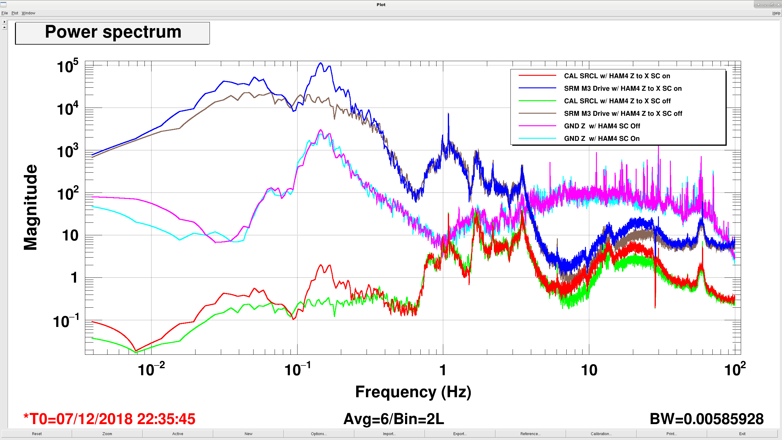
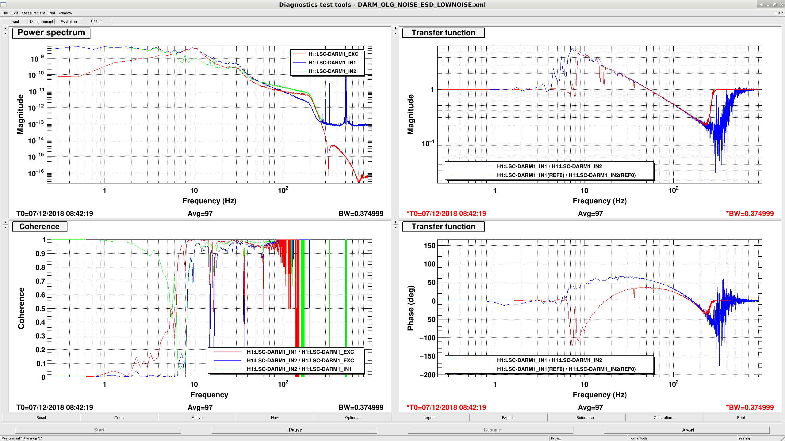
In the attached plots we showed some OLTF measurements for the hard loops at different power levels and with the RPC DC gains listed above. In order to be compared with old references (the 10 W/23 W measurements), the boosts for the hard loops were turned off during the measurements. We only measured at 20 W and 25 W. The values at 30 W were more just an extrapolation. Nonetheless the ASC seemed to be stable with those numbers at 30 W.
2. Boosts in the HARD loops:
As our knowledge on the RPC gains were improved, our effective plant did not change much during the power up, and we could actually leave the boosts (the "boost10W" in the hard loop filter banks) on during the power up. Those boosts turned out to be quite helpful as today's microseismic level was high.
Also previously the boost in CHARD YAW (FM4) was not turned on. This filter was designed for a 10 W plant and due to our previous poor RPC gain settings, it made the loop unstable. Now as we made our CH Y plant more 10 W-like, we could actually turn the FM4 back on.
3. Soft loops:
We also increased the soft pitch loops gain to have more tolerance to the potential dP/dtheta instability. This was done by turning off the FM1 in DS P and increasing CS P gain from 30 to 40. Now the soft pitch loops should have a BW of ~ 1 Hz and matched to the old reference.
We also implemented the RPC for the soft pitch loops based on our loop measurements. The values we used were
| |
DS_P |
CS_P |
| 20 W |
1 |
1 |
| 25 W |
1.5 |
1.5 |
| 30 W |
1.8 |
1.8 |
We did not exactly measure the loops at different input powers yet the settings seemed to be stable. Also to compensate for the soft mode we create digital hard mode which would stabilize the system. As a result the soft mode radiation pressure subtraction had a large error tolerance.
4. SRC ASC:
We opened the SRC loops before the power up and then measured the step responses of SRC1 error to SRM P/Y misalignment at both 20 W and 30 W. The step responses turned out to be very similar, and no sign flip was observed. We were able to re-engage the SRC ASC loops at 30 W and they seemed to be stable before the unknown fast lock losses. We also tried to leave the SRC loop on and powered up to 30 W just fine.


It could be that the solar PV charged battery that powers that gauge is low due to the cloudy, cold days we've had (we had this issue last year....need more solar! :). I looked at both these pumps yesterday and they were ON. We now have end station IPs valved in so if these BT IPs fail it's not so urgent. Gerardo and I talked about alarming on the voltage of Y2-8 & X2-8 so we know if/when the pump (or HV cable) fails.
Pressure data indicates that the pump is still pumping and that only the independently-powered CDS read-back is off.