jim.warner@LIGO.ORG - posted 16:01, Wednesday 05 December 2018 (45722)
Shift Summary
17:00 Chandra to HAM6/HAM1
19:00 Nutsinee to ISCT6
20:00 Danny TJ to EX
23:00 Danny TJ to EY
17:00 Chandra to HAM6/HAM1
19:00 Nutsinee to ISCT6
20:00 Danny TJ to EX
23:00 Danny TJ to EY
J. Kissel

I've gather a new measurement suite for the DARM loop / Sensing Function -- Results are attach, and sensing function parameters are quoted below.
The interferometer conditions during the measurement:
   - 20 W input power
   - DARM actuator configuration: EY L1, EY L2, EX L3. EX L3 ESD Bias set to -4.65 volts at the (20 bit) DAC, or -4.65 * 40 V_ESD/V_DAC = -186 V at the ESD Bias Electrode
   - all modern (red) ASC loops were engaged including SRC (36 MHz BS control, 72 MHz SRC control).
   - let the IFO thermalize for ~30 minutes or so before I began taking the measurement.
   - all calibration lines were OFF (PCAL and SUS).

The optical gain is consistent with what has recently been done to match PCAL calibration lines to DELTAL EXTERNAL (i.e. adjusting the inverse sensing function gain from 1.0 to 1.1).
This is the first quality measurement of the H1 IFO's SRC detuning since we replaced ITMX and the ETMs between O2 and O3 -- and results look good -- the optical spring frequency appears to have been reduced from between ~6-8 Hz (depending on the alignment and thermal state of the IFO) to f_s = 3.6 +/- 0.1 Hz (informed by only one measurement, 68% C.I.). The Q remains unresolved (though we expect the Q to be very close to critically coupled at ~1/2).

More details below.

The processed results based on today's measurements for the sensing function parameters are as follows:

Parameter                              | Quantiles (0.15, 0.50, 0.84)
---------------------------------------------------------------------
Cavity gain, H_c (ct/m)                | 3.245e+06, 3.249e+06, 3.253e+06
Cavity pole, f_cc (Hz)                 | 423.7, 425.2, 426.8
Detuned SRC spring frequency, f_s (Hz) | 3.441, 3.603, 3.758
Detuned SRC spring quality factor, Q_s | 30.71, 23.81, 19.41
Residual time delay, tau_c (usec)      | -2.499, -1.806, -1.112

See previous values (that informed what is currently installed and calibrating DELTAL_EXTERNAL) in LHO aLOG 44364.
Specifically, I draw your attention to the optical gain ratio of (previous / current) = 3.552e6 ./ 3.249e+06 = 1.093 ~~ 1.1, which is what's installed currently in the CAL-CS GAIN field.

If we so chose to update the sensing function filters in the CAL-CS model (probably not yet), those filters should be:
Inverse Sensing FOTON values:
H1:CAL-CS_DARM_ERR Bank
SRCD2N: zpk([425.2376;3.5282;-3.6796],[0.1;0.1;7000],1,"n")gain(1298.18)
Gain: gain(3.078e-07)

Inverse Sensing without cavity pole FOTON values for CFTD path:
H1:CAL-CS_DARM_CFTD_ERR Bank
SRCD2N: zpk([3.5282;-3.6796],[0.1;0.1],1,"n")gain(1298.18)
Gain: gain(3.078e-07)

Data was taken with the templates:
/ligo/svncommon/CalSVN/aligocalibration/trunk/Runs/O3/H1/Measurements/FullIFOSensingTFs
2018-12-05_H1DARM_OLGTF_23to800Hz_10min.xml
2018-12-05_H1_PCAL2DARM_TF_23to800Hz_2min.xml

Results were processed and produced with
/ligo/svncommon/CalSVN/aligocalibration/trunk/Runs/O3/H1/Scripts/FullIFOSensingTFs$ python3.5 process_sensingmeas_20181205.py


And updated DARM loop model comparison to come -- but we know we at least need to make the updates described in LHO aLOG 44667.
Forgot to mention -- it looks like the systematic error between PCAL and DELTAL EXTERNAL is at ~5% / 5 deg at maximum, indicating our frequency dependent systematic error in the response function is quite small -- almost at the level of O2. Nice!
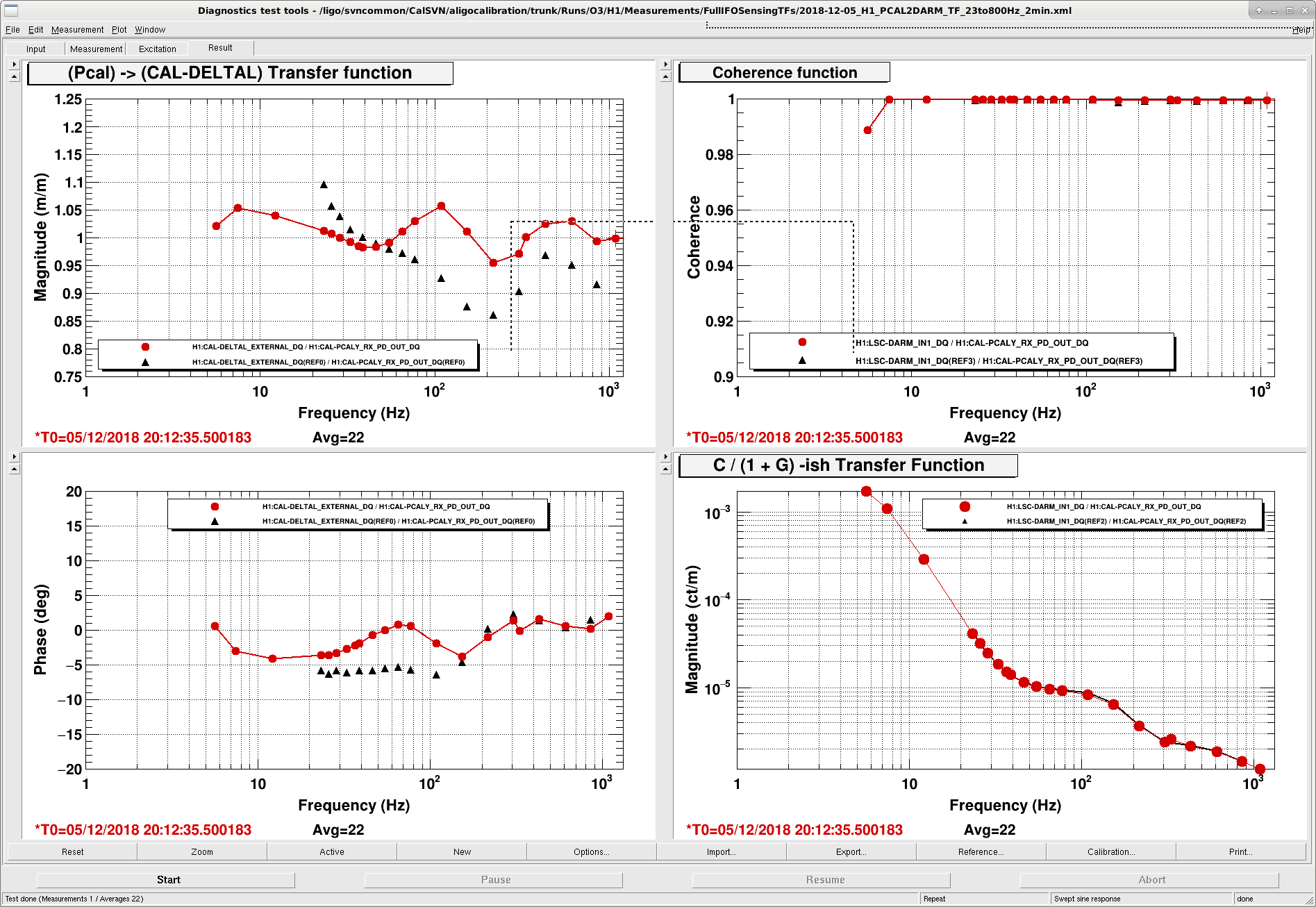
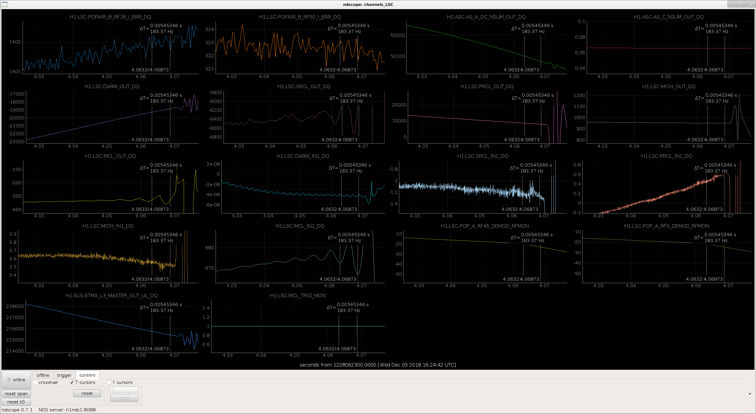
Attached is a screenshot of relevant channels that state the DARM loop parameters during this measurement suite.
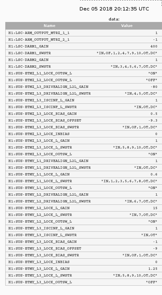
J. Kissel (in concurrence with others in the control room)

Upon investigating parameters for the DARM Loop Model, I found that the ETMY ESD Bias was ON. While some previous noise investigations have indicated that the bias doesn't impact the noise (e.g. LHO aLOG 45113), it seems bad practice (due to general charging concerns) to leave this on. Thus, I've turned OFF the ETMY ESD bias, and captured that in the SDF system (in the "safe" snap) so it sticks. Note that the HV driver is still *on*, we're just not requesting it to drive any voltage. The binary switches are in the configuration where the the low-voltage (LV) output is selected, the high-voltage input to the LV driver is disconnected, and the LV driver's low-pass filter is engaged.

Also -- while I was in there, I unmonitored the distracting "inputs to the violin mode damping filters" for all 4 quads which are controlled by guardian. There are 40 of them, so they pollute the check against the safe.snap and OBSERVE.snap SDF file when looking for other problems.
Following on from the Monday Log, thought it prudent to look closer at the V1 sensor. Plot one of that alog suggested the V1 and possibly the H1 sensors were outliers.
The first attachment here shows high and low gain responses during quiet ground motion times. You'd expect the signals to be the same unless the GM is different. All sensors show differences at lower frequencies with V1 starting to diverge at 150 mHz. Below about 70mHz, the other two vertical traces diverge while the horizontal stays similar to as low as 40mHz.
The second attachment shows all High Gain responses between quiet and large EQ times. On this plot, the before noted problem of the V1 sensor is not presenting itself, that is, all the vertical signals look similar well below 10mHz. Does this suggest the V1 low gain signal path has issues? Otherwise, why would not all the vertical sensors reflect the same GM condition...?


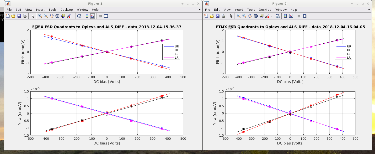
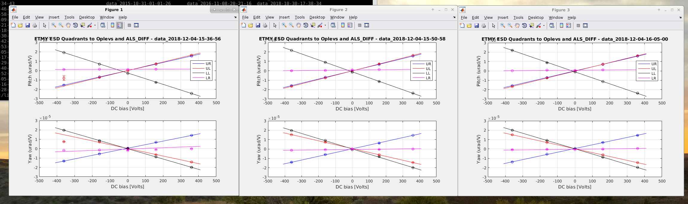
Came in a little early to run ETM Charge Measurements before Maintenance & followed the usual procedure.
Log: (Times in PDT)
Notes on the procedure/measurements:
Here are the original Slider Values (which I returned to after the measurement):
ETMx:
ETMy:

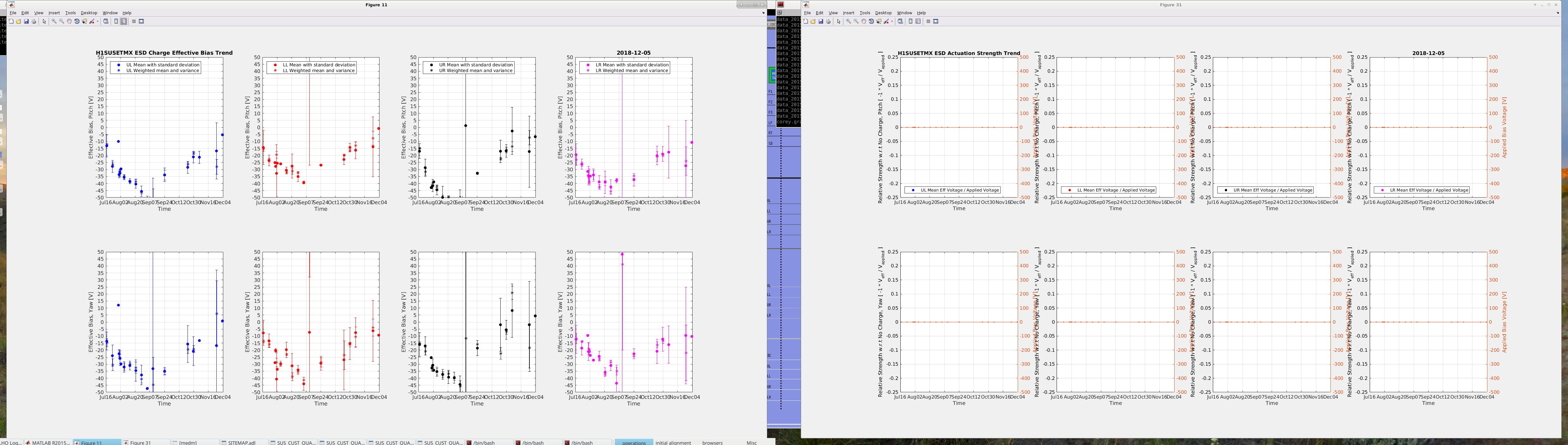
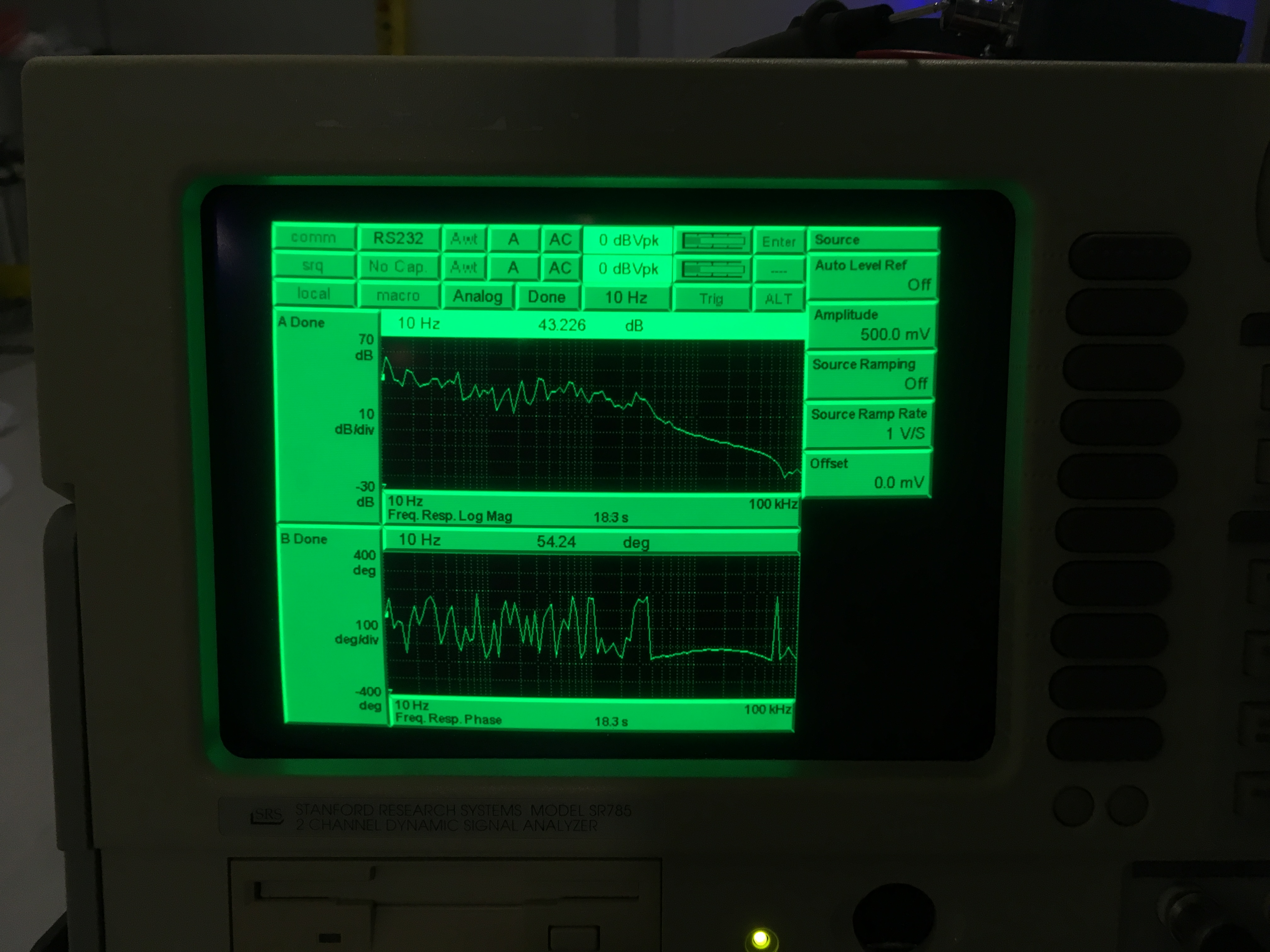
Attached a transfer function from yesterday and today along with the pump laser output.
Basically when we had >840mW, something was noisy and EOM couldn't handle it.
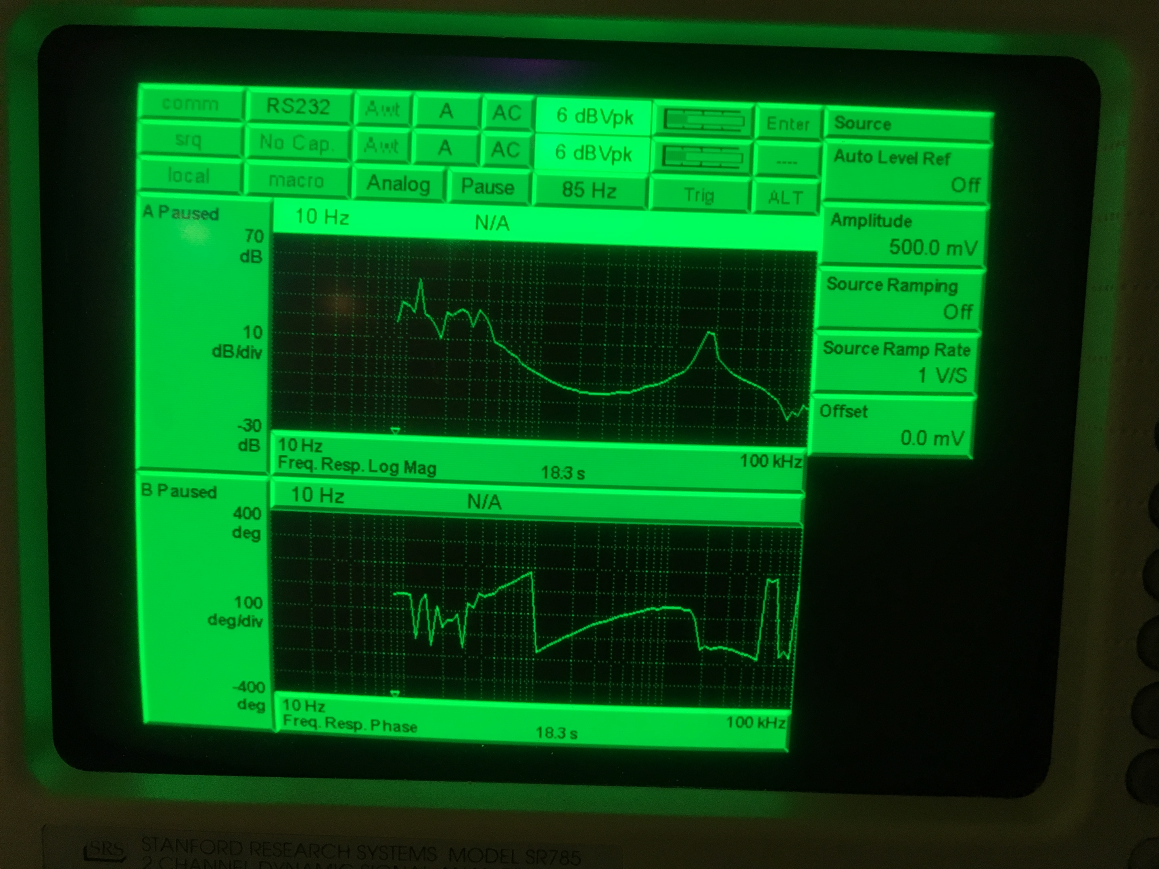
Now that we're down to 770-780mW the loop behaves okay again.
This is the laser output and green production out of the SHG (1day)

SHG scan looked fine. There was no obvious multimode or misalignment yesterday.
We had >840mW yesterday with less green production out of the SHG compared to today. Funny.

The transmission of green from the coupler to SQZT6 also has dropped to 20%. I was able to recover some yesterday with the two pick-off mirrors before the coupler but once the power started to fluctuate it's difficult to do any optimization. I'm still hopeful that this is an alignment drift issue. Would be nice to install additional picomotors there.
Note that the current temperature readout off the controller box is 29.71 C, current is 2.116A. This number has drifted since Haocun and Sheila adjusted the knob last week (alog45604, the 25 was probably 29 but I believe the decimal point to be accurate).
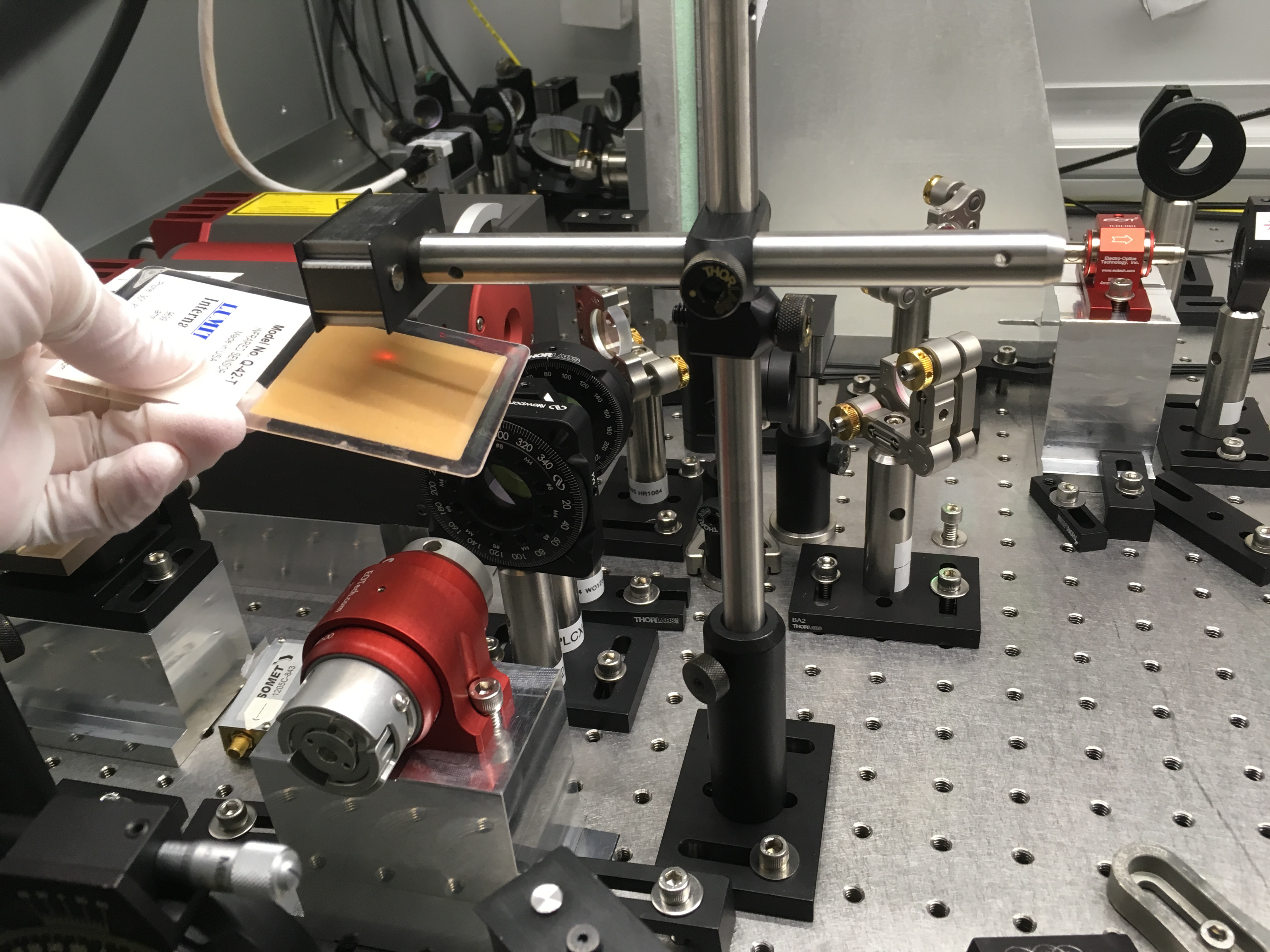
Turned out the pump laser monitor PD sees the back reflected beam from SHG. So the plot above makes sense. When amount of green power and red trans goes up, back reflected red goes down. I found that the faraday holes were never opened to let rejected light out. I also installed extra beam dump to dump the beam that shoots upward. Both beam (see attachments) shows in the photos belong to back reflection. Opening the holes seems to help with the back reflected problem that leaks into the monitor PD (though it doesn't solve the problem, hopefully it makes diagnosing issue less confusing).
I installed another Thorlabs PD to look at the Mephisto (pump) reflected beam off the first QW. This is as close to the Mephisto as I could get before it hits the faraday. The output is plugged into the extra AI channel 3 on the SQZ rack. This is just in case the monitor PD is still contaminated with the SHG back reflection (I think it still is). And might help with the diagnostic if faraday is the problem. Hopefully not...

I removed the turbo controller cables from the pumps on top of HAM 1 & 6 and parked the carts away from HEPIs.
Vacuum is now fully recovered from Nov. vent.
HAM 6 scaffolding can be removed.
Craig, Sheila (TJ on the phone)
We were warned about this EQ by seismon, which predicted an R wave velocity of 1400 um/sec (rms or peak to peak I am not sure). Since there were changes to the sensor correction automation today Craig called TJ who gave us instructions for turning it off manually. We are leaving all ISIs damped, the EQ BLRMs reached 50 um/s (rms). Nothing has tripped so far.
I was able to recover the interferometer tonight up to INCREASE_POWER.
Probably this is a readback problem and thus not that important, but there's a bump at around 10kHz in dark noise of IOP channels of LSC-REFL_A_RF9_I_IN1 and Q_IN1, coherence is large between these two channels, and both the shape of the bump and the coherence are dependent on whitening gain.
In the attached, TP_CH28 and 29 correspond to RF9_Q_IN1 and I_IN1 respectively.
Red/blue is with 12dB of whitening gain, green/brown 45dB, pink/cyan 0dB, all with two stages of whitening filters. I don't understand this.
It seems to be a small effect and these digital signals are not used for control, but we need to check if this is present in channels that are actually used for control and on the same whitening board (H1:IOP-LSC0_MADC1_TP24=POP_A_RF9_Q, TP25=I, TP26=POP_A_RF45_Q, TP27=I, TP30=REFL_A_RF45_Q, TP31=I).

When MC unlocked for whatever reason, I misaligned MC2 and PRM and measured the IOP channels that are on the same whitening chassis as LSC-REFL_A_RF9 (1st attachment), and nothing looks too crazy except REFL_A_RF9 channels (28 and 29). POP_A_RF9_I and Q (24 and 25) have a bit of a bump at around 4.2kHz or so, which shows up in POP_A_RF9_Q in-lock (2nd attachment) but it looks harmless there.
For IOP-frontend channel name relation see top left of the 1st attached.
I'll look at the analog signal of REFL_A_RF9 again on the floor, but if I find nothing I won't investigate further.


Keita, Stefan
We re-centered the green QPD offsets in full-lock (2W but with 20W soft offsets) and physically moved the Green camera back to the screen center. (work permit 7985 with Chandra's verbal approval).
We need a sturdier camera enclosure than this.
Green camera enclosure is the higher and smaller of two boxes in the attached picture.
The problem is that the entire structure is too flimsy.
You'll notice in the third picture that the screws for the lid of the enclosure are loose. Tightening these was unproductive as it twisted the structure, changing the camera pointing, and it was difficult to compensate for this by the manual adjustment of the camera (which, apparently, we have to do with the lid removed).
If you push the enclosure by your finger the camera pointing changes (though it mostly goes back to the original position after removing the pressure). If the tension of the cable coming out of the box changes probably the pointing changes though we haven't tested this.
This is really not a good system to be used as our initial alignment reference. It would be extremely useful if the camera enclosure is much sturdier (made out of metal plates instead of sheet metal, or sheet metal covering the rigid frame).


J. Driggers, J. Kissel, N. Lecoeuche, E. Merilh, H. Yu, C. Vorvick

We've had a rough time recovering from maintenance activity today, and are still struggling.

Thus far (as far as we can tell) the biggest offender appears to be debugging work on the Y-ARM Red camera system that appears to have moved the Y-ARM Green camera, thus (we think) spoiling our green alignment reference. Thus initial alignment was particularly painful (the error signals on the P/Y green camera loops were in the ~5-6 range, when they should be below 0.1), which we eventually "solved" by
    - reverting the ITMY, ETMY and TMSY alignment (via moving sliders and steering to top mass OSEM values) to the last time the green arms were locked (yesterday, Dec 4 2018 @ 10:00 UTC),
    - with ISC_LOCK set to INITIAL_ALIGNMENT, (and thus ALIGN_IFO already in SET_SUS_FOR_ALS_FPMI), set ALS_YARM to LOCK_NO_SLOW_NO_WFS and confirm that the transmitted power in the YARM is above 1.0
    - while confirming the the camera loops are OFF (using your favorite method, today we chose to hold the outputs of the camera loop filters at 0.0), set ALS_YARM to INITIAL_ALIGNMENT. This turns on the green WFS, but forces a zero to the control output of the camera servos (even though it looks like they've been turned on by the guardian.)
    - wait for the ALS WFS error signals to converge toward oscillating around zero with small amplitude. Accept that the camera loop error signals are large, and request GREEN_WFS_OFFLOADED
    - move on with the rest of initial alignment.
As such, aligning MICH was a little more difficult, and aligning the SRC was more difficult.
With this path forward, we'll not know that we have a good alignment -- and PRMI/DRMI lock acquisition will be more challenging -- until we *get* PRMI/DRMI locked, start running *red* WFS, get through the CARM reduction, get the arm HARD and SOFT loops engaged. Once we get the full red ASC systems running -- then we'll be sure to check the green camera offset settings and confirm that this was indeed the cause of our problems.

We've also noticed that the arm cavities are flashing a lot faster than normal during all of this. We suspected the great ISI model change today (LHO aLOG 45641), the potential resulting spoiling of sensor correction, and/or or the binary IO miswiring (LHO aLOG 45687), but have triple-confirmed that all settings are as normal, even though the user interface is not yet functional (thanks to TJ and Jim!).

We also have suspected the temporary settings changes on the PSL loops (PMC, ISS, FSS) that were required after the long PSL incursion today (LHO aLOG 45692), but those have been restored several hours later (i.e. after the PSL has re-thermalized) and we believe we're operating under normal conditions and performance (thanks to Jason and Cheryl).

Once we got past initial alignment, there was a small hiccup with the ETMX ESD system, which just needed to be turned ON after this morning's charge measurements were stopped prematurely. (This usually confuses the ISC_LOCK guardian's DOWN state, which has some out-of-date checks for ESD driver functionality.) This has been fixed.

Finally -- As I'm writing this log, we've also suddenly started seeing large, ~28 Hz oscillations in the red arm powers when locked on ALS COMM and DIFF.... and then now they've disappeared. The times at which we saw this problem were from about Dec 5 12:30 UTC to Dec 5 01:24 UTC.

While Jenne and Hung are sticking it out, the investigation continues with renewed vigor thanks to Sheila and Stefan, and we've only once achieved a DRMI lock.
Just a note about the ESD checks in the PREP_FOR_LCOKING state (not down). They are correct checks, it correctly did it's job (told us the ESD wasn't on) before we started trying to use it to lock ALS.
Also, the noisy ALS problem that Jeff mentioned at the end of his log was due to some bounce and roll notches in MC2 M2 L that were turned off on monday night to try to diagonse the problems we were having powering up. We've turned them back on.
J. Oberling, R. Schofield
At Robert's request I lowered the flow rates of the PSL cooling circuits by ever so slightly opening the bypass valve in the chiller room. Our target was to get the flows close to 1.5 lpm. In the past, the flow meters were happy with flows at this level (unlike when we were running with a flow closer to 1.0 lpm and the meters became very glitchy). Robert will assess how this small change effects PSL table motion; I will keep an eye on the flow meter readings to see if they become glitchy again.
Flow rates before change:
Flow rates after change:
Attached are the relevant flow rates for the last 2 days; the change in flow is clearly seen. What looks like a single glitch shortly after the change is actually not. While we were in the PSL enclosure Robert requested that we slightly open the bypass valve on the manifold (the valve on the old HPO crystal cooling circuit) for a few seconds to release any trapped air bubbles. This is the cause of the apparent flow glitch, not an actual glitch in the reading from the flow meters. Therefore, after >24 hours there have been no glitches in the flow rate. I will continue to monitor this, but so far everything looks stable.

Danny, Craig, Dan Brown
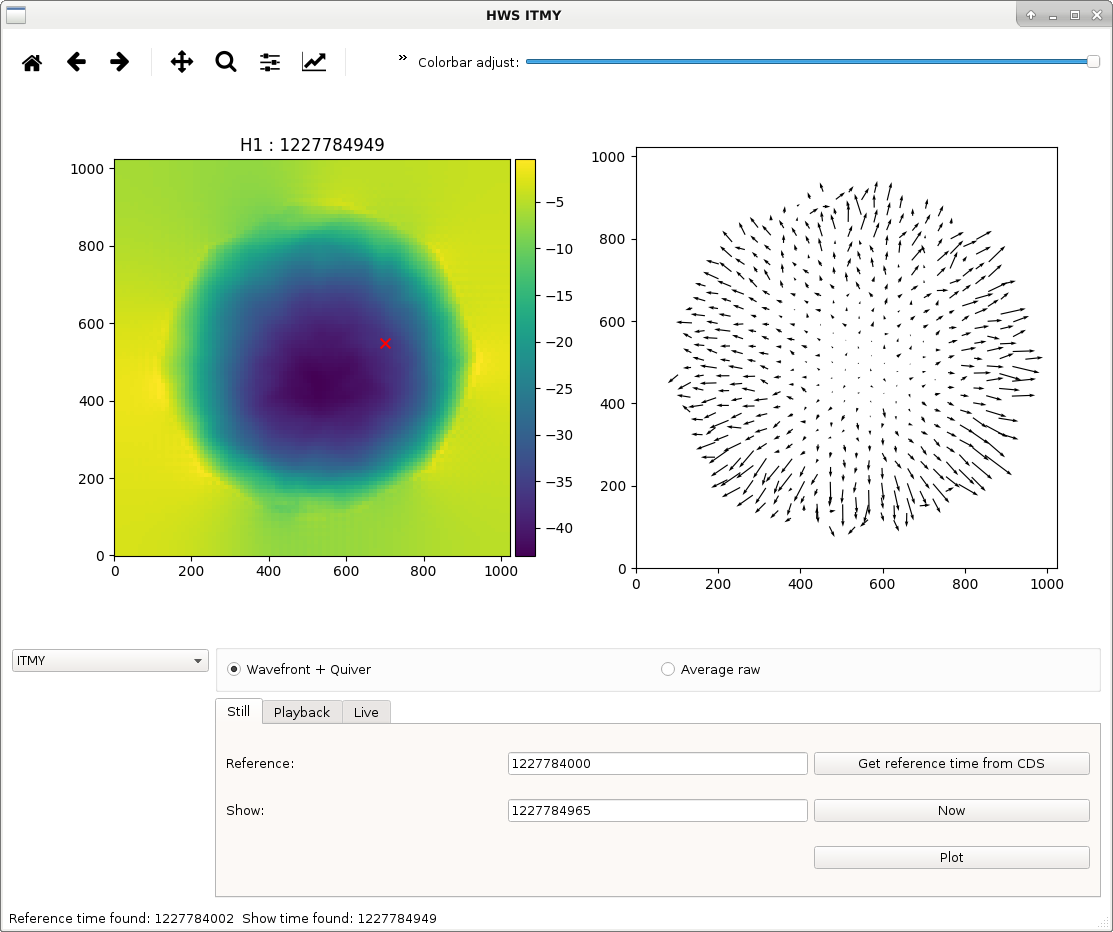
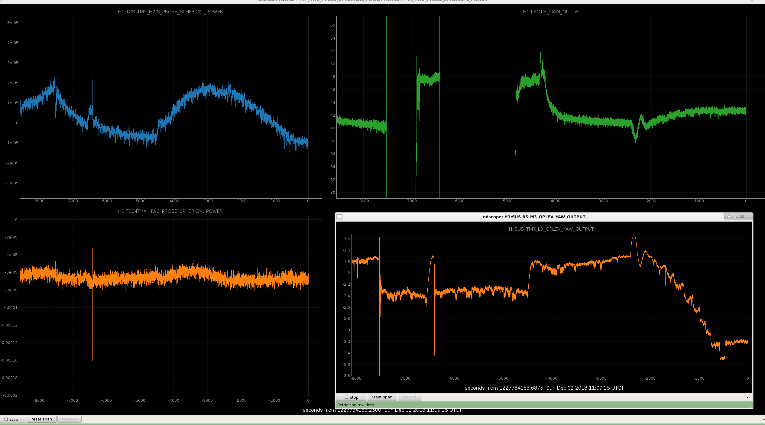
We had a long lock run in low noise tonight. During this we were adjusting the PRC1 offset resulting in some slight alignment drifts of the BS and ITMs (45623). You can see the affect this has on the HWS spherical power here. The alignment offsets started around -3000 seconds on the time axis, first in pitch and then in yaw.
This drift was enough to see how the self heating spot moves relative to the HWS probe beam: ITMY before and after. The red cross is where the IFO beam was before the vent. The other thing to notice is that by choosing the reference time for when the point absorbers have heated up we can get the wavefront distortion without them included, so we see the broader absorption. We also ramped the CO2 heater to get a position of the CO2 relative to the interferometer beam, which is noticeably offset.
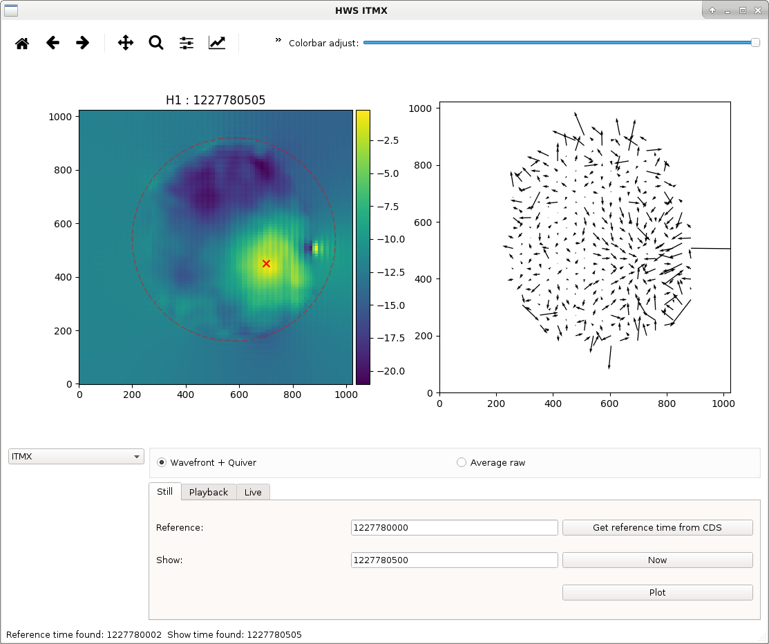
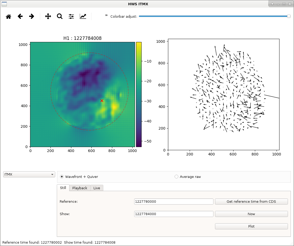
We did the same alignment shift images for ITMX, before and after. For ITMX the self heating spot wasn't in a bad position to begin with, however with the new offsets it's become misaligned to the HWS probe beam, so we need to do some picoing.
Lastly, we ramped CO2Y up and down to find the position on HWSY but also to see how the PRC gain and noise was affects. Turning the CO2Y power up 2X resulted in the ASC becoming unstable and noise increased at low frequencies, PRC gain didn't really change. Turning it down 1/2X did the same, DHARD yaw became unstable and we lost lock. We did notice a high frequency bump appearing at several kHz, similar to the frequency noise bump when changing the CO2 laser significantly. More investigation needed on that though. When HWSX is sorted out again we'll run some better comm and diff CO2 tuning.


Added movie of ITMY point absorber heatup. First movie is with a reference before powerup. The second is using a reference when the point absorbers have reached a steady state. Zip files contains Numpy compressed npz files, each of these have the wavefront aberration data for the CO2 reduction and the ITMY heatup without point absorbers.


