Danny V., Dan Brown, TVo
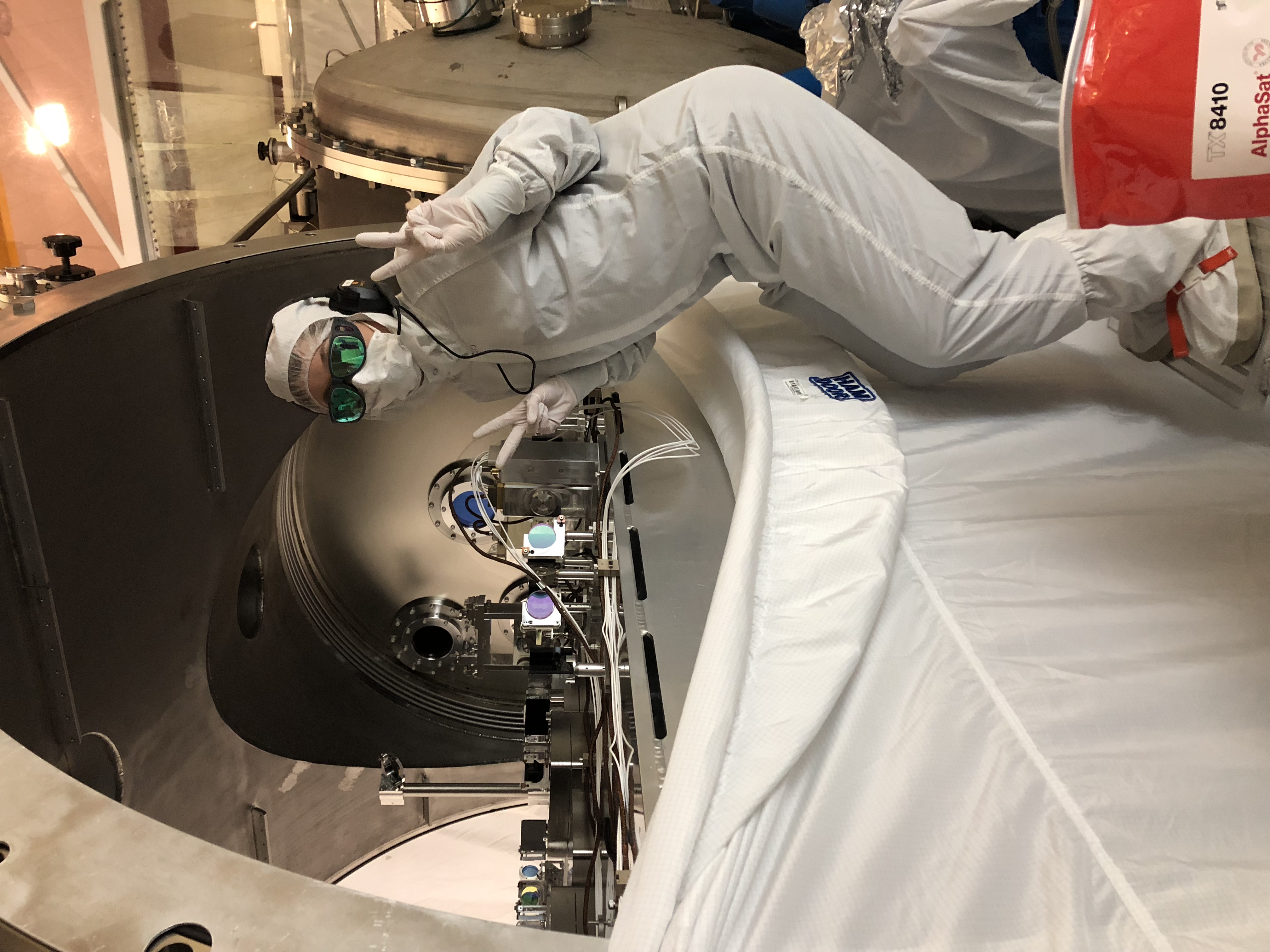
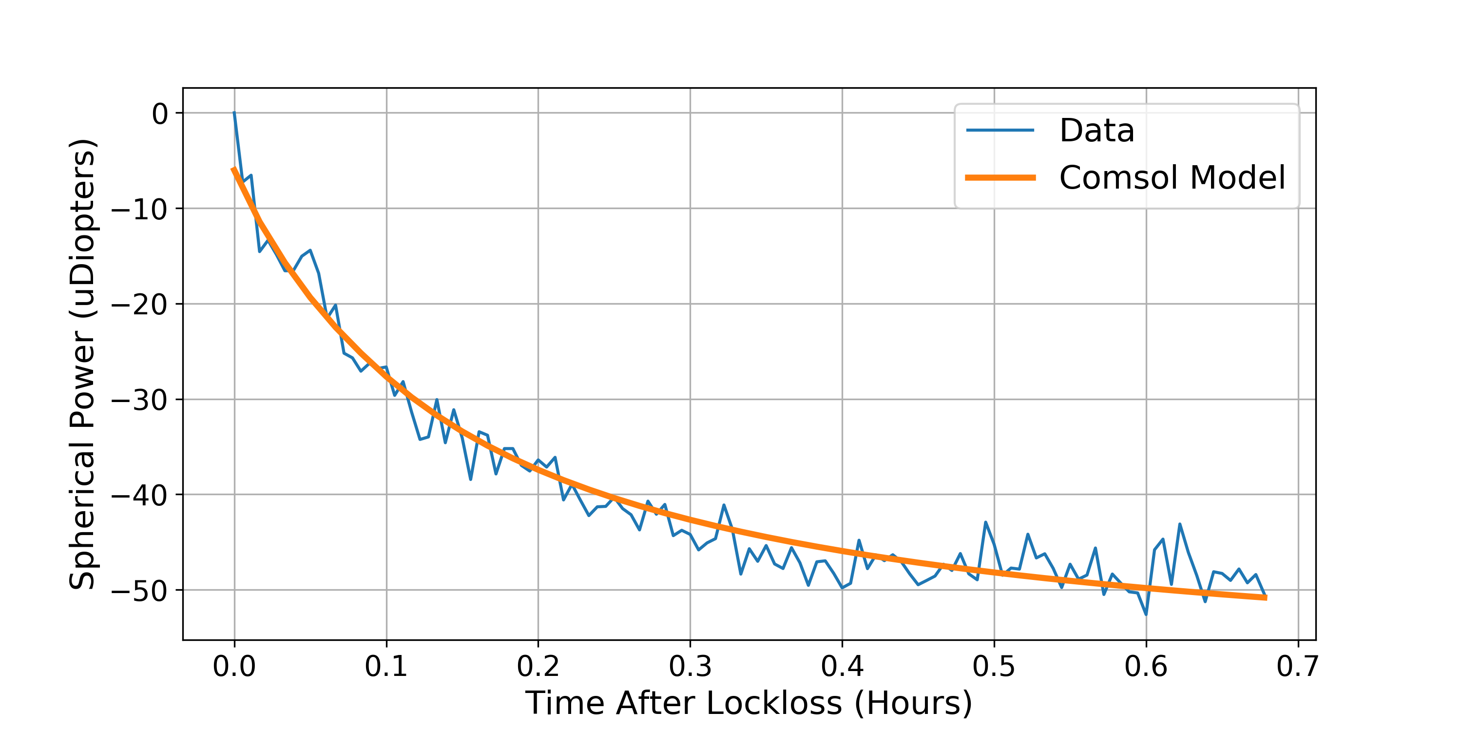
During one of the lock losses last week, we paused the CO2 compensation on both ITMs in order to get an absorption measurement with just IFO cooling. Also during this time, Dan did some post processing on the Hartmann data in order to better fit the spherical power to the wavefront distortion. Previously, the HWS code provided did not take into account for an offset in the IFO beam relative to the center of the Hartmann camera and Dan was able to add the ability to re-fit using the IFO beam as the center and this has cleaned up our data a lot. With this new data we use the exponential decay from a COMSOL model from this ALOG-14634 and provides a pretty good fit for both ITMs ( Figure 1 and 2), the largest uncertainty is estimated by varying the starting time for our fits from when the lock loss actually occurred because the optics swinging around caused a lot of noise in the Hartmann sensor. It should be noted that we haven't subtracted any point absorbers from the ITMY data which will over-estimate the amount of ring heater compensation, this means that we could have some CO2 left over at 50 watts for CO2Y.
ITMX absorption: 304 +/- 38 ppb
ITMY absorption: 804+/- 42 ppb
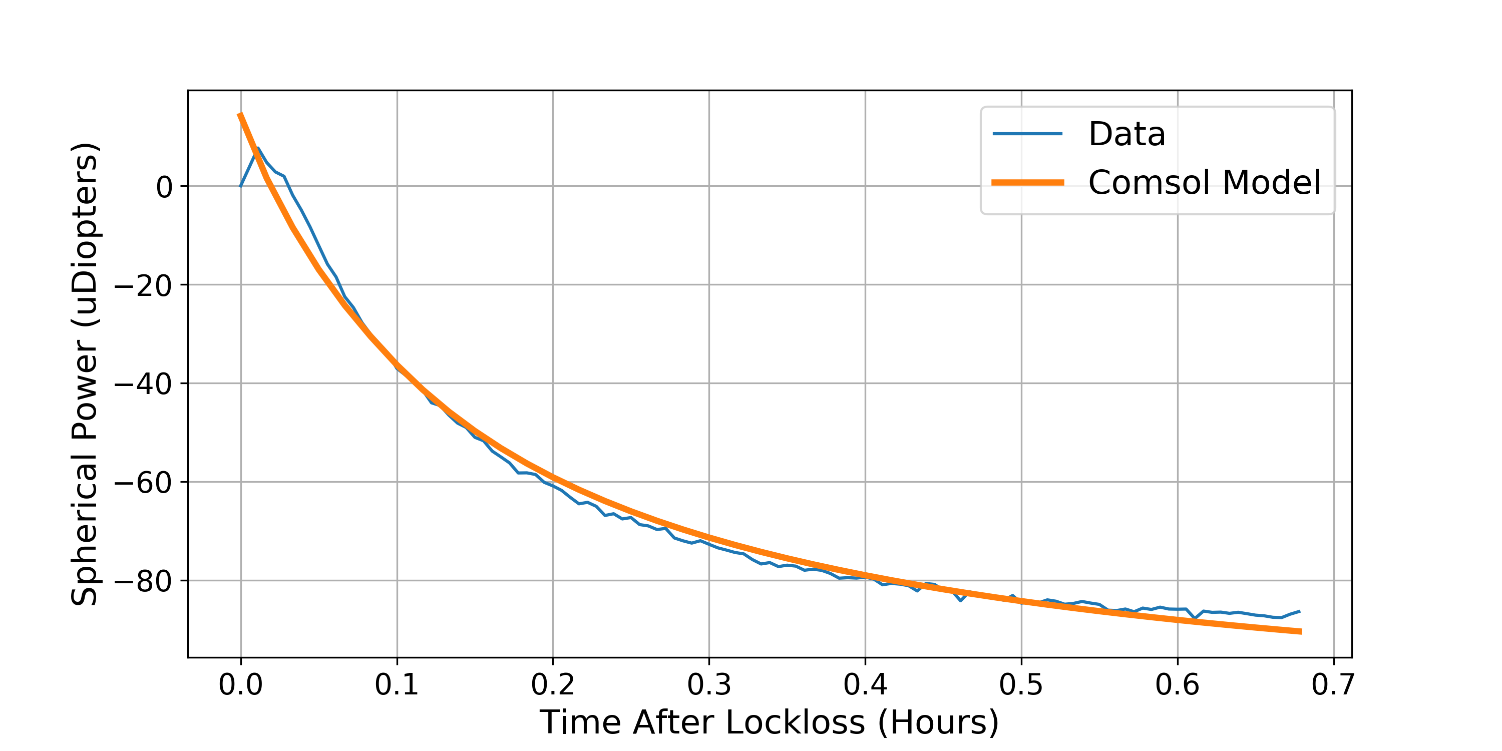
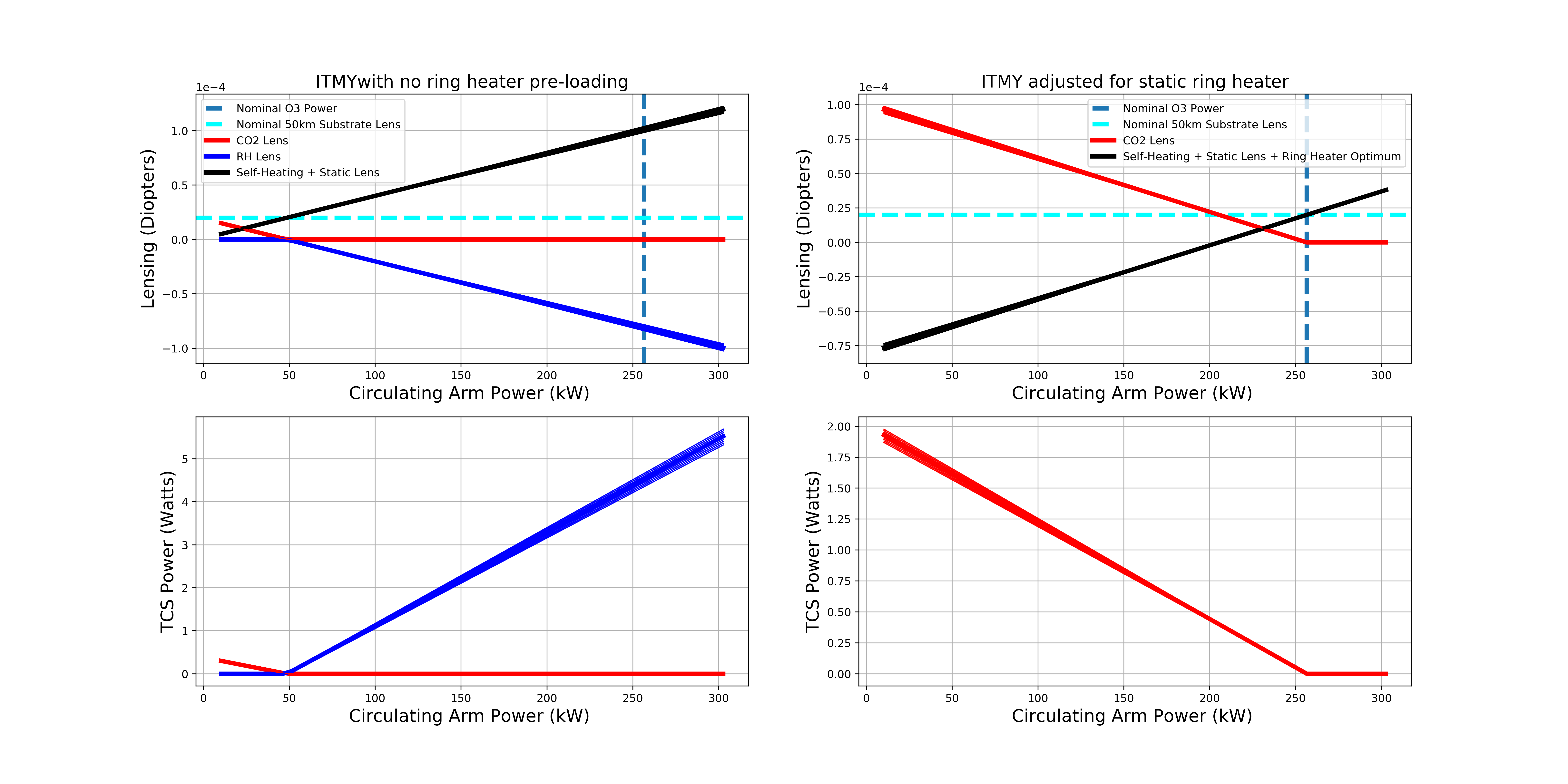
Figure 3 and 4 provide the pre-loading settings estimates for 50 Watts using this absorption data and some actuator calibrated numbers which we fine-tuned during this quiet vent break (while the corner is under vacuum but HAM1&6 are open) , interestingly, the amount of spherical power for ITMX-CO2 differs ITMY-CO2 by a factor of two according to the HWSs, we're still trying to track this down.
Parameters used to work out the TCS settings for O3 (diopters/watt):
#factor of 2 for the double pass
RH_SUBdef = -2*9e-6
#factor of 2 for the double pass
ITMX_CO2_SUBdef = 2*1.5e-5
ITMY_CO2_SUBdef = 2*2.5e-5
SelfSUBdef = 4.87e-4
# Parameters for surface deformation
RH_SURFdef = 9.91e-7
SelfSURFdef = -3.60e-5
Calculated O3 Actuator:
ITMX:
Self Lensing is 41.2594 uDiopters
Required RH Lensing is -0.0 uDiopters
RH Power required is 1.1811 Watts
CO2 Lensing required 42.9709 uDiopters
CO2 Power required 1.4324 Watts
ITMY:
Self Lensing is 101.4137 uDiopters
Required RH Lensing is -100.0 uDiopters
RH Power required is 4.523 Watts
CO2 Lensing required 100.4321 uDiopters
CO2 Power required 2.0086 Watts
We can dial in the CO2 laser power now and when we have reached the Paschen limit, we will turn on the ring heaters and use the HWS to track the wavefront through this process.


Now I'm checking all the models compile before we change anything.