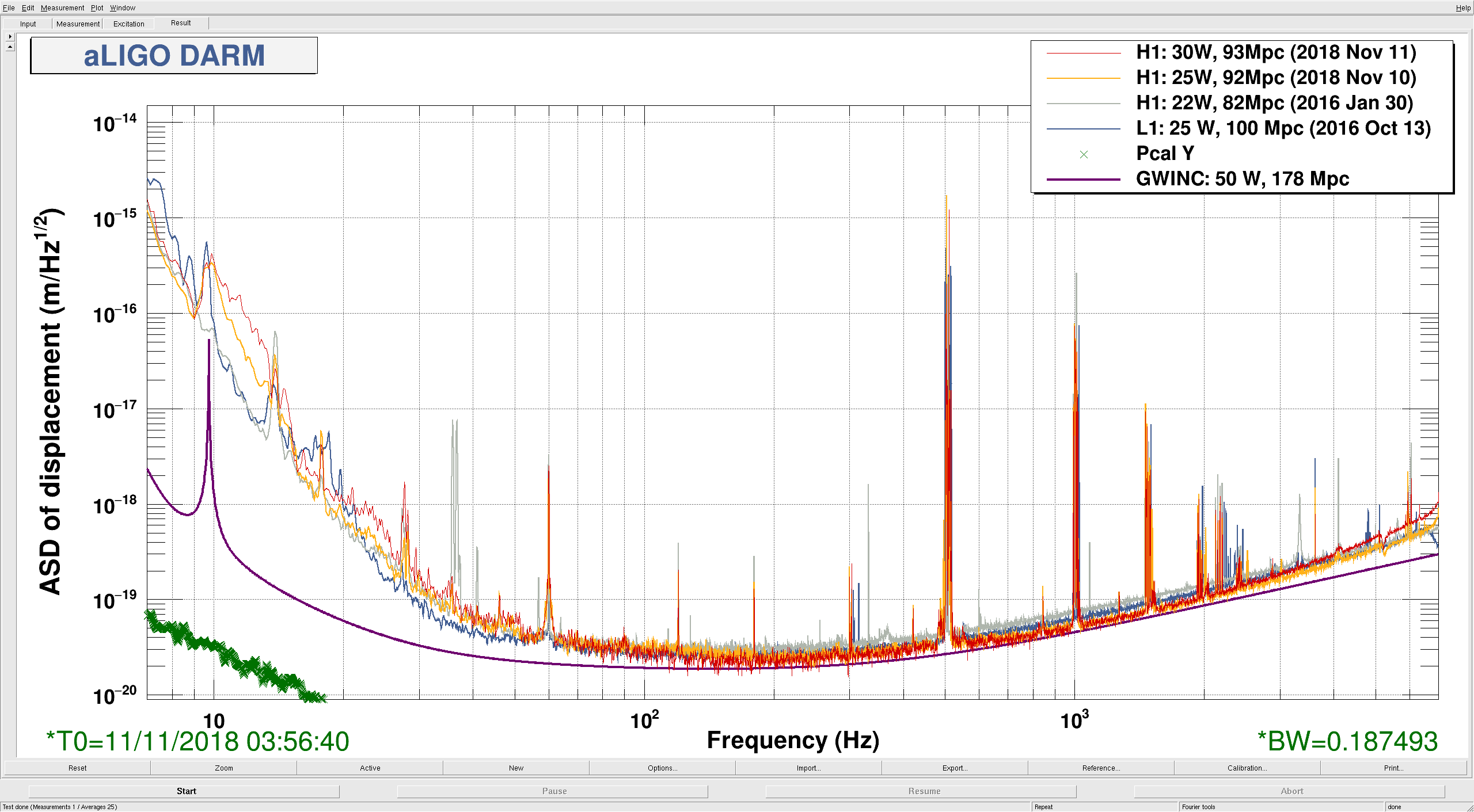
Displaying reports 44561-44580 of 83945.Go to page Start 2225 2226 2227 2228 2229 2230 2231 2232 2233 End
Reports until 16:02, Tuesday 13 February 2018
LHO General
thomas.shaffer@LIGO.ORG - posted 16:02, Tuesday 13 February 2018 (40512)
Ops Day Shift Summary

TITLE: 02/13 Day Shift: 16:00-00:00 UTC (08:00-16:00 PST), all times posted in UTC
STATE of H1: Planned Engineering
INCOMING OPERATOR: None
SHIFT SUMMARY:
LOG:

H1 SUS (CDS)
jeffrey.kissel@LIGO.ORG - posted 15:39, Tuesday 13 February 2018 - last comment - 12:50, Wednesday 14 February 2018(40517)
H1 SUS ETMY R0 F2 OSEM's Test/Coil Enable BIO Frozen in OFF Position
J. Kissel, T. Sadecki, B. Weaver

Betsy and Travis are beginning to resurrect the top mass OSEMs on the newly re-suspended H1 SUS ETMY. In doing so, they've found R0 F2 OSEM's Test/Coil Enable BIO Frozen in OFF Position. Toggling the test/coil enable (TCE) state from 0 or 1 moves all of the rest of the R0 TCE switches, but F2's remains in the stuck position. This could be either the readback stuck, which wouldn't be a priority to fix, or it could actually be the switch that's dead, which would be a major blocker for activity. 

I attach a screenshot of the M0 / R0 corner of the binary IO screen showing the problem.
Images attached to this report
Comments related to this report
jeffrey.kissel@LIGO.ORG - 15:43, Tuesday 13 February 2018 (40518)CDS
Opened corresponding FRS Ticket 9953.
filiberto.clara@LIGO.ORG - 12:50, Wednesday 14 February 2018 (40533)

This morning we looked at the electronics for the SUS test/coil enable readback for ETMY R0 F2 OSEM. Alog 40517 reports readback stuck in OFF state. We verified test/coil bit is switching inside the coil driver but the readback status change is not being captured by the binary card inside the IO chassis. Plan is to power cycle IO chassis. If error does not clear, binary card inside the IO chassis will need to be replaced.

F. Clara, R. McCarthy

H1 CDS (DAQ)
david.barker@LIGO.ORG - posted 14:06, Tuesday 13 February 2018 - last comment - 16:50, Tuesday 13 February 2018(40516)
CDS maintenace summary

Power cycle h1oaf0 in attempt to fix h1oaf overrun issue.

h1oaf0 was power cycled. The sequence was: kill models, take h1oaf0 out of the Dolphin fabric, power down cpu, power up cpu.

Note: no software was changed, no modified filter files were loaded.

The only restart issue was a brief IRIG-B negative excursion for h1iopoaf0, which invalidated the DAQ data and IPC channels for about 5 minutes.

Unfortunately, this does not fixed the h1oaf0 overrun problem (which started when h1ngn was decommissioned).

DAQ Restart

The DAQ restart was to:

use the latest H1EDCU_HEPIPUMPEX.ini

use a new H1EDCU_SEISMON.ini which I created from the new 6-eq_event code.

WP7346 Vacuum Alarms Reconfiguration

Chandra, Dave:

The cell phone alarm system was reconfigured to:

remove CP4 LN2 pump level alarms (value and error channels) from the system

increase CP4's vacuum gauge alarm level from 1.0e-07 to 5.0e-05 Torr.

The removal of CP4 LN2 pump data has impacted on the daily CP reports, which will require a code change later today.


Comments related to this report
david.barker@LIGO.ORG - 16:50, Tuesday 13 February 2018 (40522)

2018_02_13 09:42 h1iopoaf0
2018_02_13 09:42 h1pemcs
2018_02_13 09:44 h1calcs
2018_02_13 09:44 h1iopoaf0
2018_02_13 09:44 h1oaf
2018_02_13 09:44 h1odcmaster
2018_02_13 09:44 h1pemcs
2018_02_13 09:44 h1susprocpi
2018_02_13 09:44 h1tcscs
2018_02_13 11:56 h1dc0
2018_02_13 11:56 h1nds1
2018_02_13 11:58 h1broadcast0
2018_02_13 11:58 h1fw0
2018_02_13 11:58 h1fw1
2018_02_13 11:58 h1fw2
2018_02_13 11:58 h1nds0
2018_02_13 11:58 h1tw1


H1 PSL
jeffrey.bartlett@LIGO.ORG - posted 12:08, Tuesday 13 February 2018 (40515)
Changes to PSL Chiller Manifold
   Made several changes to PSL Chiller manifold in preparation for the 70w amplifier change. 

   (1). Disconnected the HPO Crystal Chamber circuit from the oscillator. Connected the supply to the return to make a short termination loop. Installed a throttling valve on the return side for flow control. Not happy with how the termination loop is configured. Looking into ways to improve the termination loop run.

   (2). Removed the laser head circuit. Connected the supply to the return port to keep water circulating until ready to connect the 70w. 

   (3). Removed and plugged off an unused circuit. 

   (4). Upgraded all the main manifold supply and return plastic fittings with all 316 SS. 
       
H1 PSL
jeffrey.bartlett@LIGO.ORG - posted 11:43, Tuesday 13 February 2018 (40513)
Change PSL Filters (WP #7337)
   Changed Crystal and Diode filters in both the chiller room and in the PSL enclosure. 

   Crystal Chiller: Some darkening of the 0.5um filter in the enclosure. This darkening runs a bit more than half way up the filter, which means there was plenty of life left in this filter. There was a small amount of debris in the bottom of the filter. One was a small piece of metal,one small piece of what looked like some sealer material, and one bit of fuzz with a tail. This looked like plastic, perhaps from the installation. 

   The 1.0um Crystal chiller filter has some slight yellowing; but no debris of any size.   

   Diode Chiller: Both the 1.0um and the 0.5um filters showed no signs of any issues with this cooling circuit. Only a very slight yellowing of the 1.0um filter. NO debris in either filter.  

   After more than a year of continuous operations all four of these filters look great. The debris found the the 0.5um Crystal chiller filter is not significant. 

Closing WP #7337      
Images attached to this report
LHO VE
chandra.romel@LIGO.ORG - posted 11:35, Tuesday 13 February 2018 - last comment - 16:30, Tuesday 13 February 2018(40514)
CP4 progress

This morning at 9:20am local I reduced CP4's LLCV setting to 0% open to cut off LN2 flow into pump reservoir. Kyle connected the HAM 6 backing cart with safety valve to CP4's turbo and will valve in turbo this morning before the pump warms up too much. Currently CP4 is at 58% full. Dave B. readjusted text/email alarms.

Mark D. is removing insulation from GN2 lines - sections that fall within bake inclosure.

Ken is removing electrical conduit, wiring, and supports and will continue this work throughout the week.

Kyle and Gerardo are stripping GV 11,12 of its wiring, controllers, annulus piping, etc.

I'm working with bake enclosure contractor on last minute "gotchas."

Images attached to this report
Comments related to this report
chandra.romel@LIGO.ORG - 16:16, Tuesday 13 February 2018 (40519)

Rather than make Kyle work the graveyard shift, I've programmed the set point of CP4 to 20% full with some flow in the transfer line. Ideally we want the pump to dry out during the day when we're in 'work mode' to monitor the turbo-scroll throughput. Reservoir is currently 45% full. Linearally extrapolating yields ~5 hrs duration to fall from 20% to 0%.

The crew made excellent progress today stripping away external components.

We valved out the small ion pump connected to the bottom of CP4. 

AIP is still pumping on GV12 due to leaky gate annulus and a pump cart is connected and running (valved out) in case of emergency.

chandra.romel@LIGO.ORG - 16:30, Tuesday 13 February 2018 (40520)

CP4 will fall to 20% full at around 11 pm tonight (if linear) but will likely happen faster.

H1 SUS
jeffrey.kissel@LIGO.ORG - posted 18:44, Monday 12 February 2018 - last comment - 09:28, Wednesday 14 February 2018(40509)
H1SUSETMY Newly, Fully Suspended Test Mass Fiber Violin Modes Mostly Measured
J. Kissel, T. Sadecki

Travis and I used a HeNe Laser, QPD, and speaker array to begin characterizing H1SUSETMY's PUM-to-TST fused silica fiber violin modes. We were able to complete the characterization of 3 of the 4 fibers, but we began to have (we believe to be) electronics problems during characterization of the last fiber, so we've left the set turned off but otherwise as is, in hopes the the gremlins will go away by tomorrow morning to characterize the final fiber.

I've exported the data, and intent to process it in detail as I've done for ITMX (see LHO aLOG 39163), but for now preliminary results are as follows (under the "Answer" column):

Freq resolution 62.5mHz
(400 lines with 25 Hz span)

+X / +Y (S1400157; Partial Suspended Fundamental: 504.5 Hz)

	Freq Band / Hz	Answer / Hz	nAvgs	Exc Amp / mV		FileName
1st 	490 515		504.8 		10 	250 		0003
2nd 	990 1015	999.8125	10	250 		0004
3rd	1460 1485	1471.3125	10	250		0005
4th	1975 2000	1980		10	250	        0006
5th	2450 2475	2460.3125	10	500 		0007
6th	2925 2950	2939.625	10	500 		0008

-X / +Y (S1400159; Partially Suspended Fundamental: 503.0 Hz)

1st	490 515		503.625		10	500		0009
2nd	990 1015	1000.3125	10	500		0010
3rd	1460 1485	1470.375	10	500		0011		
4th	1975 2000	1979.4375	10	500		0012
5th	2450 2475	2459.4375	10	500		0013
6th	2925 2950	2939.375	10	500		0014

+X / -Y  (S1800486; Partially Suspended Fundamental: 513.25 Hz)

1st	500 525		512.75		10	500		0015
2nd	1000 1025	1016.8125	10	500		0016	
3rd	1490 1515	1500.375	10	500		0017
4th	1975 2000	1979.5625	10	500		0018
5th	2450 2475	2459.375	10	500		0019
6th	2925 2950	2939.3125	10	500		0020


So far, the difference between fully suspended and partially suspended values look consistent with the ~0.5 Hz shift down in frequency as seen on ITMX.

Note, we tried upgrading the HeNe laser to a spare fiber-coupled optical lever laser as requested by Angus in LHO aLOG 40300, but the output coupler we were given collimated the beam to much larger than we needed (a ~10mm beam for a ~3mm QPD). Also, we were seeing a large amount of glitch-like impulses while taking the ASD of the QPD SUM output. A scope, time-series reading of the QPD output showed no glitching at any time scale. Suspecting the new laser, we tried out the old, supposedly noisy one. Simultaneously, I found that the SR785 input settings were DC coupled, and switched to A-B with AC coupling. Either the laser swap or the AC coupling fixed the problem, but since we were on a roll, we didn't switch back to the new spare optical lever laser. All of today's measurements were taken with the old HeNe laser.
Comments related to this report
jeffrey.kissel@LIGO.ORG - 09:28, Wednesday 14 February 2018 (40525)
I've fully processed the data, and I'm sad to say that this data set us much more poor than what we got for ITMX (LHO aLOG 39163).

(1) With all of the electronics problems, and the lack of outside-world wifi at the end stations, we couldn't look at ITMX's results results during the measurement, and I ended up chasing features of the electronics above the 3rd harmonic. In other words, the frequencies of the ~2kHz and above modes are junk. Don't trust them.

(2) We didn't spend the time to characterize the partially suspended violin mode fibers beyond the fundamental, so the comparison between partially suspended and fully suspended is not as complete.

Attached are the same plots as before however, just for consistency.

Below is the completed table -- to the best we can -- for the fully suspended, in-air violin mode measurements.

Fiber       S/N         Harmonic     Partially      Fully       df (F-P)
+X / +Y     S1400157    1st          504.5          504.81       +0.31
                        2nd          No Data        999.81       n/a
                        3rd          No Data       1471.31       n/a

-X / +Y     S1400159    1st          503.0          503.63       +0.63
                        2nd          No Data       1000.19       n/a
                        3rd          No Data       1470.38       n/a

+X / -Y     S1800486    1st          513.25         512.75       -0.50
                        2nd          No Data       1016.75       n/a
                        3rd          No Data       1500.31       n/a

-X / -Y     S1800491    1st          510.5          509.88       -0.63
                        2nd          No Data       1008.69       n/a
                        3rd          No Data       1492.31       n/a

Please note I state in the above entry that "So far, the difference between fully suspended and partially suspended values look consistent with the ~0.5 Hz shift down in frequency as seen on ITMX." From the table in this entry, it is obvious this is incorrect, and some skew up and others skew down in frequency.
Non-image files attached to this comment
H1 CAL (CAL, ISC, SUS)
evan.goetz@LIGO.ORG - posted 18:29, Monday 12 February 2018 - last comment - 16:34, Wednesday 28 March 2018(40508)
Compensation zero moved from ESD output filter bank
Evan G., Jeff K.

We moved a compensation zero out of the ESD output filter bank for each quadrant that had generated an uncompensated 5.2 kHz pole in the DARM loop (see LHO aLOG 33927). This resulted in an effective delay of ~20 usec. There is adequate roll off already from a low pass filter in the ESD driver, so moving this out of the DARM loop will be minimally impactful. Instead, the compensation zero will be a compensation pole in the CAL-CS path and doesn't result in an additional 5.2 kHz zero being added to the Foton filter.

We leave the filter in place and turned on, but the design string is now simply zpk([], [], 1, "n")

The new filter is installed in CS_DARM_ANALOG_ETMY_L3, FM5: zpk([], [3245.33075], 1, "n") (this comes from the mean of the summing node poles, see 27619)

Removing this from the DARM path means that we need to include these as an uncompensated poles in the DARM model and reduce the unknown actuation delay by 20 usec. This will bring the unknown actuation delay down to ~40 usec.
Comments related to this report
jeffrey.kissel@LIGO.ORG - 16:34, Wednesday 28 March 2018 (41189)
Associated with FRS Ticket 7351.
LHO VE
kyle.ryan@LIGO.ORG - posted 16:45, Monday 12 February 2018 - last comment - 20:08, Monday 12 February 2018(40506)
CP4 decommissioning status
see WP #7343 

1630 hrs. local -> Lowered CP4's level via CDS PI control set point to 70% down from 75%.  I expect this new pump level value should be reached prior to my leaving tonight.

Will start tomorrow morning with step 2 of WP #7343 (as step 1 was done this weekend).  Delay is the result of competing employee requirement/task in addition to my desire to complete construction of a relay box that will act as a second interlock and isolate the scroll pump as a function of foreline pressure.  As is, the foreline isolates only at the absence of 120VAC as seen by the scroll pump motor windings (i.e. one layer of protection - prefer two layers).  
Comments related to this report
kyle.ryan@LIGO.ORG - 18:41, Monday 12 February 2018 (40510)
1830 hrs. local -> Lowered CP4 level target down to 65% from 70%
kyle.ryan@LIGO.ORG - 20:08, Monday 12 February 2018 (40511)
2010 hrs. local -> looks stable.  Going home now.
H1 AOS (CDS, DetChar)
joshua.smith@LIGO.ORG - posted 16:25, Monday 12 February 2018 (40505)
First impressions of units in NDS2

Cross-posting from LLO alog here: https://alog.ligo-la.caltech.edu/aLOG/index.php?callRep=37737 

H1 SUS
betsy.weaver@LIGO.ORG - posted 16:03, Monday 12 February 2018 (40504)
ETMX AERM07 Prism #1 glued

Today, I knocked out the jig calculations for the AERM07 prism placements and updated the spreadsheet for all 4 new AERMs (05, 06, and 08 have been finished, spreadsheet E1000828).  Gerardo did a quick spotcheck of my work, then I went to the lab and glued the first prism on (specifically "180 ARM").  The EP30-2 epoxy is a newly procured vial and passed the usual pre-bake test, as usual.

LHO General
thomas.shaffer@LIGO.ORG - posted 16:00, Monday 12 February 2018 (40492)
Ops Day Shift Summary

TITLE: 02/12 Day Shift: 16:00-00:00 UTC (08:00-16:00 PST), all times posted in UTC
STATE of H1: Planned Engineering
INCOMING OPERATOR: None
SHIFT SUMMARY: PSL was shut down and 70W amplifier work began. More work continuing down at MY for CP4. Team SUS working on ETMY. And SQZ crew is prepping for next week's install.
LOG:

H1 IOO (IOO, PSL)
cheryl.vorvick@LIGO.ORG - posted 12:59, Monday 12 February 2018 (40501)
PSL ISS Second Loop (in HAM2) QPD segment offsets set

Given that we have no laser light, confirmed by images of the PSL and cameras looking into HAM2, I set the PSL ISS Second Loop Array QPD dark offsets.  I accepted the values into SDF, and also had to accept the offset switch being on for all 4 segments, and I've confirmed that these offsets were zero in Feb 2017, during O2.

OFFSETS: Seg1 = 0.180, Seg2 = 0.180, Seg3 = 1.540, Seg4 = 2.370, and the SUM, which had been at +4.2, is now oscillating around zero.

I put an offset of -2.0 on the SUM to prevent it from going negative.  I tried using -1.0, but the pitch and yaw signals were still occasionally railing +/-32K.  The SUM during Feb 2017 reached 60K counts, so an offset of -2.0 is small.

Changes are recorded in the attached screenshot:  Left side shows current settings, rich side shows a snapshot of the QPD segment settings as found (zeros).

Images attached to this report
H1 PSL
sheila.dwyer@LIGO.ORG - posted 12:53, Saturday 10 February 2018 - last comment - 15:52, Monday 12 February 2018(40480)
PSL is off

I came in to do some last DRMI/PRMI tests, and found the laser is off.  This happened about 4:15 am pacific time.  THe epics channels don't show any problems with the chillers, and it looks like the power watch dog tripped after the laser went off. (screenshot attached)

Images attached to this report
Comments related to this report
sheila.dwyer@LIGO.ORG - 15:56, Saturday 10 February 2018 (40481)

It looks like this possibly was the power watchdog. The NPRO power and currents have been stable since the HPO has been off, but the PSL-AMP_PWR channels show that the power had been dropping before the laser shut off.  The Beckhoff status screen shows that everything is normal except the power watchdog. 

Images attached to this comment
sheila.dwyer@LIGO.ORG - 18:04, Saturday 10 February 2018 (40483)

Jason logged in remotely and restarted the PSL.

peter.king@LIGO.ORG - 05:32, Monday 12 February 2018 (40490)
Various data trends are attached.  At the time the power watchdog was engaged the output power was ~34.8 W.
There is no indication that the power decreased by 15% since the watchdog was enabled.  Trend data also
suggests that the amplifier dropped out before the NPRO.
Images attached to this comment
peter.king@LIGO.ORG - 15:52, Monday 12 February 2018 (40503)
Indeed the front end laser was tripped off by the power watchdog.  The trigger signal for the watchdog is the output of the third
amplifier stage and not the output of the front end - something that is rectified with the upcoming front end laser modifications.
When the watchdog was last engaged the power was ~106.  The watchdog tripped in at ~90, ie at the 15% drop level.  So the watchdog
worked as it should.

    Oh and the drop in power is most likely due to the large drop in relative humidity.  We know the e-beam sputtered coatings
for the pick-offs have issues with relative humidity.
Images attached to this comment
H1 ISC
sheila.dwyer@LIGO.ORG - posted 18:40, Friday 09 February 2018 - last comment - 14:15, Monday 12 February 2018(40477)
measuring spot positions in PRC

This afternoon Georgia and I locked PRMI and ran a2l for PRM, PR2, and PR3.  

  PRM PR2 PR3
P2L 1.099 0.173 2.614
Y2L 0.046 -8.34 -0.050

There is a file called by the a2l scripts (for the matrices) that is no longer in the place it used to be.  We added the ads matrix to the list of matrices used in ISC_library, so that these scripts now import and use that.  

Comments related to this report
georgia.mansell@LIGO.ORG - 14:15, Monday 12 February 2018 (40502)

I have converted these P2L and A2L values to spot position using Alexa and Kiwamu's numbers for the HSTS (PRM & PR2) and HLTS (PR3), shown in alog-14788, and the same maths as in alog-40422.

  A2L L_{euler} a_{euler} alpha spot position* [mm]
PRM p 1.099 .25 5.2382

0.0524

-2.21
PRM y

.046

.25 5.2382 0.00220 0.0926
PR2 p .173 .25 5.2382 0.00826 -0.348
PR2 y -8.34 .25 5.2382 -0.398 -16.797
PR3 p 2.614 .25 2.4096 0.271 -14.2
PR3 y -0.05 .25 2.4096 -0.00518 -0.492

*spot position relative to center of mirror, face-on.

H1 ISC (ISC)
thomas.vo@LIGO.ORG - posted 20:31, Tuesday 06 February 2018 - last comment - 16:52, Monday 12 February 2018(40447)
Loss Measurement, Locked and Unlocked XARM

[For the commissioning team]

We did a quick measurement of the loss in the x-arm after improving the pointing into the cavity using IM4 and PR2.

It is important to note that there were no angular loops closed when doing this measurement, so the power build up wasn't optimized ( LSC-TR_X_QPD_B_SUM ~ 0.95).   We were running short on time and verified that the DC angular alignment was good enough so that the locked vs unlocked state gave us a big enough dip to estimate a visibility.  

Channel Locked Power(Cts) Unlocked Power(Cts) Visibility Loss PPM (calc'd)
AS_A_DC_NSUM 286 307 93% 302

Comparing the above numbers to alog-38493. They are close, but I can't say anything definitive about the change in loss between the two ITMXs (before and after swap), we can redo this measurement when we have more time to close angular loops (and maybe try a more sophisticated loss measurement).  Also important to note, mode-matching contributes to the loss as well and this is not taken into account with this measurement.

Images attached to this report
Comments related to this report
thomas.vo@LIGO.ORG - 16:52, Monday 12 February 2018 (40498)

Sheila commented that the visibility/loss is a bit concerning, so I trended some other channels to see if they gave any other estimates, unfortunately, the ones I could think of (REFL and AS) were not of much use because they didn't show an obvious dip (First and second attachment) .  It is important to also note that the dark offsets for ASC-AS_A_DC_NSUM were on and roughly correct.

That got us thinking, if there is alignment or modal mismatch, will we be over or under estimating the total loss with this measurement? And how much does the modulation depth from the sidebands cause a difference in the power ratio between unlocked and locked compared to the losses of the ITM?

Using Finesse and the as-built Nebula page, I modeled the  single x-arm with input power of 1 W.  The modulation depths for 9 and 45 MHz was measured by Kiwamu in aLOG-8867.  Also, setting the arm cavity eigenmodes as the basis, I estimated 15% mode-mismatch and 15% alignment mismatch by injecting 01 and 02 modes alongside the 00 into the cavity.  Another parameter is of course the loss at the input coupler which for display purposes I used 5ppm. (Third attachment)

Conclusion:

The loss of the input-coupler dominates over the modulation depth from the sidebands, and the mismatch either from modal or misalignment will cause us to underestimate the total losses.

Images attached to this comment
Displaying reports 44561-44580 of 83945.Go to page Start 2225 2226 2227 2228 2229 2230 2231 2232 2233 End