After successfully subtracting the Sidles-Sigg torque for the yaw HARD modes (LHO:44349), we are now able to subtract the pitch modes as well.
To compensate for the HARD modes, we need to digitally send in a torque signal corresponding to the soft mode motion. This means if we over-subtract the SS hard mode, we will create a digital soft mode which de-stabilize the system. To avoid such a situation, we should deliberately under-subtract the hard mode so that small errors in the radiation compensation path won't de-stabilize the plant. Consequently, instead of aiming to recover the free (0 W) pendulum, we only compensate the suspension back to the plant corresponding to 10 W input power (~ 65 kW arm circulating power).
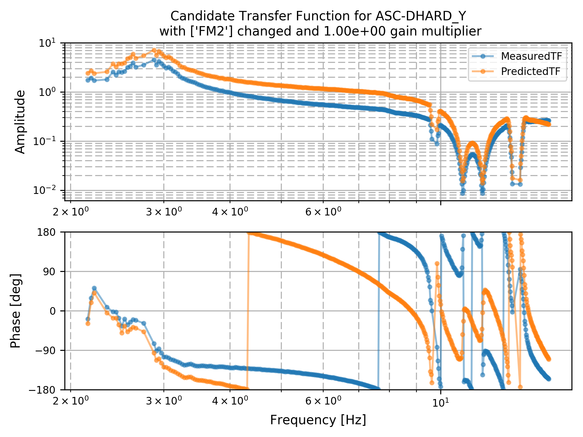
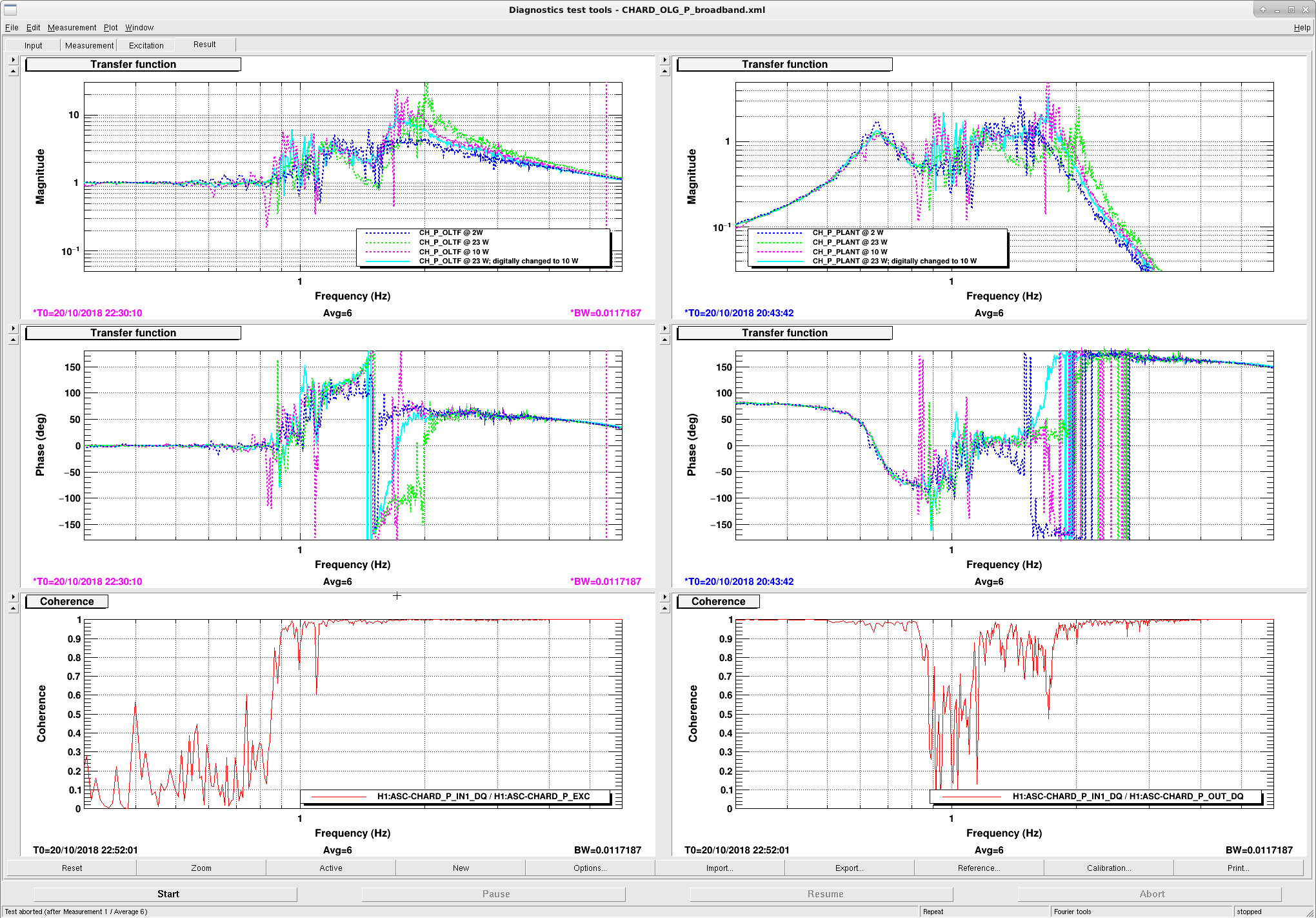
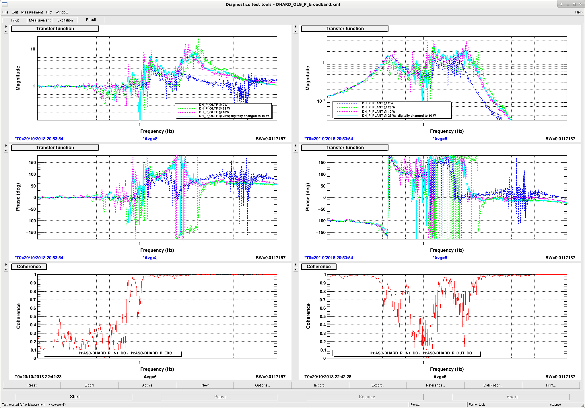
Please see the attached plots for the results. The first one is for CHARD and second for DHARD.
In the plots the left panels correspond to the OLTF (IN2/IN1), and the right ones proportional to the suspension plant (OUT/IN1).
We use the following color convention: blue for 2 W input power, pink for 10 W input power (no digital compensation), green for 23 W input power (no digital compensation), and cyan for the 23 W input power together with digital subtraction of the SS torque. As said above, we intentionally subtract the plant back to the 10 W one instead of the 2 W one so that the subtraction is robust against both fluctuations in arm power & the sensing (i.e. the optical) gain.
In the future to use the RPC, we should put in a gain corresponds to
RPC gain = sign(ASC ctrl) * (P_in - 10 W) / (10 W),
where sign(ASC ctrl) is the sign of the DC gain in the regular ASC ctrl filter bank. E.g., currently the DHARD ASC ctrl filters have negative gains, then the sign of the RPC for the DHARD P/Y should be negative.


Recovery started a few minutes ago. So far, resetting all SEI watchdogs and then requesting "recover EQ" seems to be bringing everything back online.
Suspensions reset okay, and I also brought the SEI_Config node to windy_nobrsx, so we've got sensor correction going as well.