peter.king@LIGO.ORG - posted 06:14, Wednesday 26 September 2018 (44169)
ISS
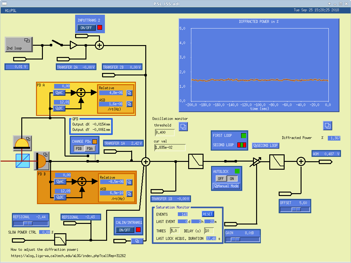
Yesterday I tried to get some pieces of the puzzle as to why the second loop ISS is not suppressing as
it should. Starting off with the first loop.
I confirmed that there are only 4 positions of the half waveplate in 360 degrees that correspond
to maximum output of one of the ISS photodiodes, PDA in this case. There is no reason to believe why
this would be any different for PDB. The positions of the rotation stage were 90 degrees apart,
indicative of the half waveplate rotating the plane of polarisation as it should. Naively this would
confirm that only one polarisation is incident on the photodiode. As a check a polarising beamsplitter
cube was inserted between the two mirrors that steer the output of the pre-modecleaner into the ISS
PD box. Oriented to transmit horizontally polarised light, no reflected light was observed when an
IR viewer was used. This would seem to confirm that there is only one output polarisation. This
does not explain the lack of suppression with the second loop however.
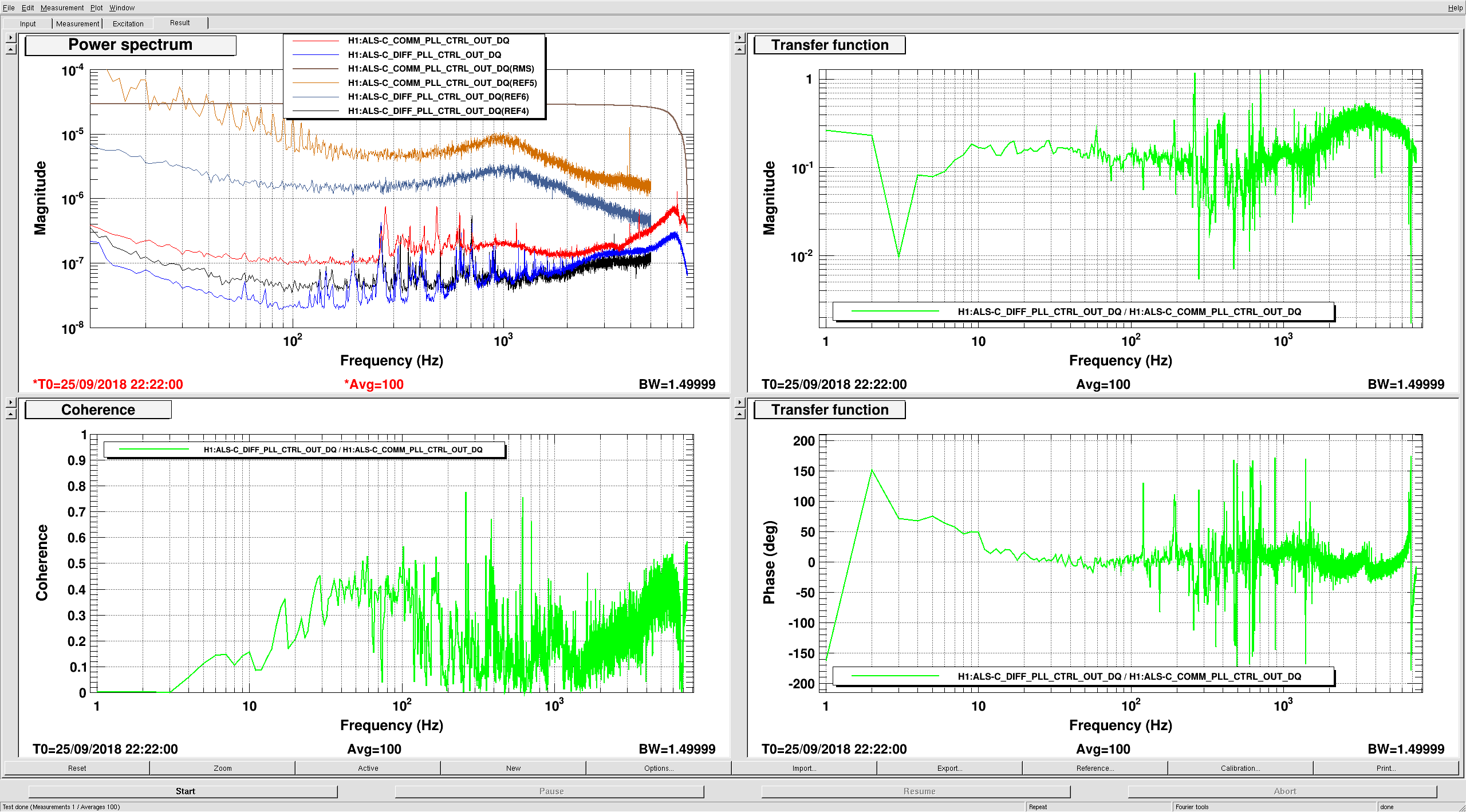
The UGF with the gain slider at 8.0 was measured to be 82 kHz with a phase of -170.6 deg. Looking
at the power noise at 1 kHz, there was ~50 dB of suppression (as measured by the out of loop photodiode
PDA) with the integrators off. With the integrators on, there did not appear to be any extra noise
suppression. With the gain slider at 0.0, the UGF was 33.7 kHz with a phase of -137.4 deg. At 1 kHz
there was ~40 dB of suppression with the integrators off and somewhere between 2 and 3 dB more with the
integrator on.
The polariser was subsequently removed and the hardware restored.