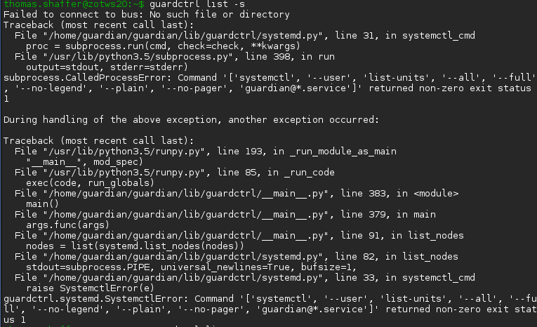
Displaying reports 45461-45480 of 86634.Go to page Start 2270 2271 2272 2273 2274 2275 2276 2277 2278 End
Reports until 16:02, Thursday 07 June 2018
H1 AOS
yannick.lecoeuche@LIGO.ORG - posted 16:02, Thursday 07 June 2018 (42388)
Shift Summary - Day

TITLE: 06/07 Day Shift: 15:00-23:00 UTC (08:00-16:00 PST), all times posted in UTC

STATE of H1: Planned Engineering

INCOMING OPERATOR: None

SHIFT SUMMARY:

14:53 (7:53) Jeff B to LVEA H2 Chiller Room -- look for parts

15:00 (8:00) Start of shift

15:06 (8:06) Ken to EX, EY -- electrical work

15:40 (8:40) Jeff B back from LVEA

15:50 (8:50) Christina to EX, EY -- drop off first aid kits

16:50 (9:50) Jason to PSL enclosure -- investigate temperature spike

16:54 (9:54) Jeff B to EX -- recover contamination control kit

16:57 (9:57) Marc to MX -- testing vault magnetometer

17:03 (10:03) Hugh to EX -- check out HEPI pump

17:31 (10:31) Jeff B back from EX

17:31 (10:31) Jeff B to PSL -- make measurement

17:45 (10:45) Jason to LVEA

17:50 (10:50) Hugh back from EX

18:18 (11:18) Georgia and Craig to EX -- pack up EFM equipment

18:22 (11:22) Ed and Jason to EX -- pack up alignment equipment

18:33 (11:33) Marc back from MX

18:48 (11:48) Craig and Georgia back from EX

19:11 (12:11) Jeff B out of PSL enclosure

19:30 (12:30) Jason and Ed back from EX

19:41 (12:42) Jeff B and Jason to PSL enclosure -- make sure environmental controls are set right

19:50 (12:50) Jeff B and Jason back from PSL enclosure

20:28 (13:28) Fil to LVEA‌ -- Beckhoff upgrade preparation

20:35 (13:35) Gerardo to EX -- purge air skid

20:51 (13:51) Ken to EX -- work on overhead door switches

21:07 (14:07) TVo to LVEA -- Set up barriers around CO2 laser tables, open and start them, inject CO2 into chamber

21:12 (14:12) Marc and Ed to vault

21:40 (14:40) Ken back from EX

22:25 (15:25) Marc and Ed back from vault

22:59 (15:59) TVo back from LVEA

23:00 (16:00) End of shift

H1 PSL
daniel.sigg@LIGO.ORG - posted 14:15, Thursday 07 June 2018 - last comment - 16:08, Thursday 07 June 2018(42386)
Wrong reference cavity resonance

Noticed that the EX ALS laser wouldn't lock. After last Tuesday, the PSL was locked to the wrong reference cavity resonance. Unfortunately, this shifts the frequencies of the ALS and SQZ lasers by ~600MHz.

Non-image files attached to this report
Comments related to this report
daniel.sigg@LIGO.ORG - 15:04, Thursday 07 June 2018 (42387)

And something oscillating in the FSS...

Non-image files attached to this comment
keita.kawabe@LIGO.ORG - 16:08, Thursday 07 June 2018 (42389)

As for frequency, refcav temperature was (and still is) swinging, we need to wait until things settle down: https://alog.ligo-wa.caltech.edu/aLOG/index.php?callRep=42377.

As for oscillation, PMC transmission used to be ~43W, dropped to ~20 and was continuing to go down until they tweaked the alignment today, at which point it got back to ~40W. So this might have been just UGF getting too low.

Images attached to this comment
H1 ISC
daniel.sigg@LIGO.ORG - posted 12:11, Thursday 07 June 2018 (42384)
New ALS Parameters

The new green power transmission coefficients for the test masses are:

  Old New
ETMX 37% 7.9%
ETMY 32% 7.9%
ITMX  1.1% 0.96%
ITMY 1.1% 1.1%

Assuming 10 mW input power, the expectations for the new arm cavity parameters are:

  Old New
  X-arm Y-arm X-arm Y-arm
Finesse 13 16 68 67
Cavity Pole 1.4 kHz 1.2 kHz 275 Hz 280 Hz
Intra cavity power 83 mW 99 mW 390 mW 380 mW
Reflected power 9.1 mW 8.9 mW 6.2 mW 5.8 mW
Transmitted power 0.9 mW 1.1 mW 3.8 mW 4.2 mW

The attached plot shows cavity power and PDH signals for fundamental, first-order and second-order modes as function of round-trip wavelength. The left column is for the old cavity parameters.

Non-image files attached to this report
H1 PSL (PSL)
yannick.lecoeuche@LIGO.ORG - posted 11:14, Thursday 07 June 2018 (42383)
Weekly PSL Chiller Reservoir Top-Off

Added 50 mL to crystal chiller

H1 CDS
patrick.thomas@LIGO.ORG - posted 11:11, Thursday 07 June 2018 (42382)
Two additional NIC cards added to h1ecat0
Finished WP 7631. The HEPI pump servo appears to have continued to run unaffected.
H1 PSL
jason.oberling@LIGO.ORG - posted 10:38, Thursday 07 June 2018 (42381)
PSL PMC Beam Alignment Tweaked

E. Merilh, J. Oberling

We tweaked the beam alignment into the PMC this morning (done via picomotors from the control room).  When we started the PMC was transmitting ~19 W, upon finishing the PMC was transmitting ~39.8 W.  This is not quite at the 42 W we were transmitting after Peter and I installed the ISS AOM; this may be due to the temperature being ~10 °F hotter than normal, will monitor the PMC trans once PSL temps return to normal.

After the tweak we turned the ISS ON.  The Reference Signal was set to -1.70V, which gives a 1.5% diffracted power percentage.

H1 PSL
edmond.merilh@LIGO.ORG - posted 09:45, Thursday 07 June 2018 - last comment - 10:19, Thursday 07 June 2018(42377)
PSL Weekly Report - 10 Day Trends FAMIS #6739

70W Laser power anomalies due to Bulls-eye swapping and calibration. All other plots seem nominally ok.

Images attached to this report
Comments related to this report
edmond.merilh@LIGO.ORG - 09:58, Thursday 07 June 2018 (42378)

Oversight: There seems to be something shifty about the temps around the table. Jason is out investigating.

Images attached to this comment
jason.oberling@LIGO.ORG - 10:19, Thursday 07 June 2018 (42380)

The lights in the laser room were left on after the last incursion (this is on us, as we were the last ones in there Tuesday evening) and the make-up air was OFF.  This is surprising as Rick and myself confirmed (via listening for the fan to make sure it was running) the make-up air was ON when we left the enclosure Tuesday evening.  It's entirely possible that after a long day in the enclosure I was mistaken when I thought I could hear the make-up air fan running (at the 20% level we run during Science mode, it is difficult to hear the fan) when in actuality it wasn't.  The lights have been turned off and the make-up air fan is now running at 20% (confirmed via listening for the fan.  I checked multiple times while I was out there to hopefully make sure I wasn't fooling myself).  Jeff B. and Robert both want to make quick trips into the enclosure this morning, so this will give us an excuse to turn the AC on and get the temps back down to a normal level.

H1 IOO (IOO, ISC, PSL)
georgia.mansell@LIGO.ORG - posted 23:07, Wednesday 06 June 2018 - last comment - 11:19, Friday 08 June 2018(42373)
Beam jitter on PSL bullseye PD

Thomas, Sheila, Georgia

Summary

We have calibrated the width, pitch, and yaw outputs of the PSL bullseye PD, accounting for the larger beam size incident on the detector.

We then compared the PSD at the bullseye with the IMC-WFS (on reflection, measured with IMC unlocked) and IMC-IM4_TRANS (with IMC locked) to look for jitter coupling.

The jitter measured by the bullseye PD is 2-3 orders of magnitude below the WFS noise, implying that our jitter does not originate from the 70 W amplifier.


Bullseye PD calibration

Keita reported yesterday on the installation of the bullseye PD, on a pick off directly after the 70 W amplifier stage (alog 42344). TVo and I set about updating the filter banks, which convert the individual segments to width, pitch and yaw, relative to the beam width on the photodiode. We calculated the beam width based on the power on the outer and inner segments, and following Vaishali and Kiwamu's note (DCC-T1700126) calculated the new responses. The new gains are:

g_width = 0.55

g_pit = 0.61

g_yaw = 1.06

Which is only a few percent off the previous gains.


Comparing bullseye PD and IMC spectra

To calibrate the bullseye PD, IMC-WFS, and IMC-IM4_trans such that they can be compared quantitatively, we did a calibration similar to alog 39434 - including the PMC and IMC suppressions, and converting the IMC PDs to units of beam width. The bullseye raw data is multiplied by the PMC and IMC suppressions; the IMC-WFS data is multiplied by the IMC suppression and the factor of sqrt(pi/8) to convert to units relative to beam width, and the IMC-IM4_TRANS data is multiplied by the factor of sqrt(pi/8).

The PMC suppression was calculated from DCC-T0900616, S_PMC = 0.0163. The IMC suppression was calculated from DCC-T060269, and the finesse from DCC-G1400096, giving S_IMC = 0.0039.

The calibrated plot is attached. The bullseye PD spectra are well below the IMC-WFS (showing lots of jitter) and IMC-TRANS traces.

Images attached to this report
Comments related to this report
thomas.vo@LIGO.ORG - 00:07, Thursday 07 June 2018 (42375)

Attached is the spectra of the bullseye photodiode, now versus O2.  The references are from 20170817, which show significantly higher noise in pit, yaw, and wid compared.  This supports the idea that the 70W amplifier has much lower jitter motion and the increased jitter seen at the IMC_WFSs (aLOG-42362‌ and aLOG-41947) could be coming from something downstream of the laser.

Images attached to this comment
daniel.sigg@LIGO.ORG - 08:53, Thursday 07 June 2018 (42376)

Somewhat puzzled. The plot indicates that at 10-100Hz the jitter as measured by IM4 is larger than before the IMC, but coherent with the bullseye at the 0.1 to 0.3 level!?

How are the IMC WFS DC signals calibrated? The DC signals are good for measuring jitter, when unlocked. In the past, we had to apply a 1/3 factor when locked, see alog 34845.

georgia.mansell@LIGO.ORG - 10:03, Thursday 07 June 2018 (42379)

I interpreted the plot to mean that the noise on IM4-TRANS is too high to see the jitter. I forgot to mention that the broadband coherence between the bullseye and IM4-trans depended on the incident laser power and looked much higher at low powers. This confused me as well.


Also note in this plot the WFS was measured at ~5W input power (if I've remembered correctly) while the IM4-TRANS was at ~17W input power.

keita.kawabe@LIGO.ORG - 12:57, Thursday 07 June 2018 (42385)

Vaishali/Kiwamu's document calculates dw/w/sqrt(2) instead of dw/w where dw is the beam radius change and w is the beam radius, both at the detector, you need to multiply sqrt(2).

The normalized amplitude of the first radial LG mode that the detector is sensitive to is dw/w, not dw/w/sqrt(2).

I'll leave the check of PIT and YAW calculation to Georgia and Thomas.


If you're interested:

The misunderstanding might have come from some confusion about HG VS LG but I'm not sure.

When the waist size of the beam changes from w0 to w0+dw0 and the waist is displaced by dz, the resulting beam will be expressed by a linear combination of the lowest LG mode LG0 and the first LG radial mode LG1 as

E = LG0 + (dw0/w0+i*dz/zR/2) * exp(i*2*pG) * LG1

where zR is the Rayleigh range and pG is the Gouy phase at the detector. The amplitude of the higher order mode is abs(dw0/w0+i*dz/zR/2), not dw0/w0/sqrt(2) nor dw/w/sqrt(2).

Only the real part of LG1 term is detected as the change of the beam radius when you use DC detector like Bull's eye. pG rotates the complex mismatching parameter and selects the DOF that is measured. For example if pG=0 (detector is at the waist) or +-pi/2 (the detector is in the far field) abs(dw/w)=abs(dw0/w0), and the detector is insensitive to the waist position change to the first order. If pG=+-pi/4 (detector is away from the waist by Rayleigh range) dw/w=-+dz/zR/2 and it's insensitive to the waist size change.

In general, the radius change at the detector is

dw/w=dw0/w0*cos(2*pG)-dz/zR/2*sin(2*pG)

and the detector is insensitive to the orthogonal DOF i.e.

dw0/w0*sin(2*pG)+dz/zR/2*cos(2*pG).

thomas.vo@LIGO.ORG - 11:19, Friday 08 June 2018 (42401)

Georgia and I checked the Pit and Yaw calibration for how Vaishali and Kiwamu scaled the units and they are in terms of dw/w which Keita had pointed out is the correct way to compare the bullseyes to the QPD.  So we'll change the calibration factor of the width by a sqrt(2) and leave pitch and yaw alone.

H1 IOO (IOO, ISC)
sheila.dwyer@LIGO.ORG - posted 22:55, Wednesday 06 June 2018 (42372)
MICH_BRIGHT dither alignment, IMC unlocking

This afternoon and this evening the IMC has not been staying locked for long, 10-30 minutes at a time.  Thomas and I checked the OLG, which seems fine at around 40kHz.  The alignment of the IMC also seems fine. 

I don't know what the problem is.  Earlier this afternoon I disabled the ISS since that was railing, Jason is planning to adjust the alignment into the PMC in the morning which will probably help.  We can see if the PMC adjustment tomorrow helps with the problem.  

We were planning to set up a single bounce measurement with the IMC VCO scan, but since it is a long measurement it won't work with the IMC not staying locked.  

Earlier tonight I also started a guardian state for a MICH dither alignment in the ALIGN_IFO guardian.  The plan is to replace the step that operators do by hand in the initial alignment, Craig and I I edited PREP_MICH_BRIGHT_ALIGN to set up the oscillators and demods, and checked that the signals look promising.  This job will also be easier to finish with the IMC staying locked.  

H1 TCS (TCS)
aidan.brooks@LIGO.ORG - posted 19:05, Wednesday 06 June 2018 (42371)
HWS code moved out of USERAPPS folder

I’ve removed the HWS code from the current working copy of the CDS SVN. These changes are in Committed Revision 17358.

We're moving the code to a separate GIT repo so we can get a working copy back up to the sites.

(see LLO aLOG 39308)

H1 AOS
suresh.doravari@LIGO.ORG - posted 18:08, Wednesday 06 June 2018 - last comment - 16:51, Thursday 07 June 2018(42370)
ETMY oplev 3rd whitening stage switched on & Laser moved to quieter location.

[Robert S. , Jason O., Suresh D.]

Objective: 

    1) At present the oplev signal is dominated by electronic noise above 1 Hz.  In attempt to see if increasing the whitening helps wished to increase the whitening stages on the signal.

    2) We wished to investigate the EMI emission from the He-Ne laser power supply using the magentometer.

Things we did:

    1) First, Robert investigated the EMI emissions.  During this process we shifted the location of the He-Ne laser and its power supply to a new location that is further away from all other power supplies and electronic devices.   See picture below.  Robert will report on the results of this investigation in a separate alog.

    2) Then Jason switched on the third analog whitening stage and also the digital dewhitening stage on the ETMY oplev QPD segments.  The new dip-switch state on the binary switch card is attached.  

Note:  We also reduced the gain by about 20dB, because at high gain of 39dB, switching  on the third whitening stage probably caused saturation of  an opamp in the chain and the output signal flipped sign.  

We will analyse ETMY oplev signals under this new condition and see if we can get a better signal to noise ratio than before.

Images attached to this report
Comments related to this report
robert.schofield@LIGO.ORG - 16:51, Thursday 07 June 2018 (42390)

The laser power supply is quite noisy as shown in the figure. In addition to broad band noise there is also a 2 Hz comb, and it draws a lot of power, about 30W. I compared it to a rouge switcher that somehow made it into the VEA and the magnetic noise was orders of magnitude louder from the laser power supply. All of these observations suggest it may be a noise source. I think that we would need to do a more careful test when DARM is at high sensitivity before we could be sure that the noise from the laser power supply will not be a problem. Short of passing this further test, I dont think we should let the SIOS SL-03 in the VEA.

Images attached to this comment
H1 SUS
jeffrey.kissel@LIGO.ORG - posted 17:18, Wednesday 06 June 2018 (42367)
Progress on Suspension Health Checks Post-Pump-Down
J. Kissel

I'm slowly working through measuring the standard health-check transfer functions and ASDs for all suspensions now that most chambers are closed and pumped down. I'm seeing a few suspicious things along the way that I'll need to go back and run more tests (see "notes" below), but for now I'm moving on when I see weird things, trying to get all that are "OK to GO" measured and confirmed good. I list the progress below. Where there are suspensions that are "OK to GO" I list the date of the measurement.


Suspension       Measured          Data Processed       Notes
RM1              Not Yet                n/a
RM2              Not Yet                n/a

MC1              Not Yet                n/a
MC3                 |                    |
IM1                 |                    |
IM2                 |                    |
IM3                 |                    |
IM4                 |                    |
PRM                 |                    |
PR3                 V                    V

MC2              Not Yet                n/a
PR2              Not Yet                n/a

BS               Not Yet                n/a

ITMX             M0 done, R0 Not Yet    Not Yet           

ITMY             M0 done, R0 Not Yet    Not Yet

ETMX             Not Yet                n/a
TMSX             Not Yet                n/a

ETMY             Yes                    Not Yet            All good. 2018-06-05_2125, 2018-06-05_2244
TMSY             Somewhat                                  Suspiciously nasty Roll to Roll TFs. Need to investigate further.                    

SR2              M1 done                Not Yet            Icky looking results with currently desired alignment offsets. Took "no offsets" data -- looks good. Need to investigate further

SR3              M1 done                Not Yet            All good. 2018-06-06_2256 
SRM              M1 done                Not Yet            Icky looking results with currently desired alignment offsets. Took "no offsets" data -- looks good. Need to investigate further
OFI              M1 done                Not Yet            All good. 2018-06-06_2308
ZM2              M1 done                Not Yet            All good. 2018-06-06_2323

OM1              Not Yet                n/a
OM2                 |                   n/a
OM3                 |                   n/a
OMC                 |                   n/a
ZM1                 |                   n/a
OPO                 V                   n/a    
LHO VE (VE)
gerardo.moreno@LIGO.ORG - posted 17:15, Wednesday 06 June 2018 - last comment - 17:23, Wednesday 06 June 2018(42368)
X-End MTP Now On Scroll Pump

Switched the configuration from QDP80 to scroll, to be able to do the switch, pump down was interrupted for a bit.

Comments related to this report
gerardo.moreno@LIGO.ORG - 17:23, Wednesday 06 June 2018 (42369)

4 hour trend data of X-End pressure during MTP modifications.

Images attached to this comment
Displaying reports 45461-45480 of 86634.Go to page Start 2270 2271 2272 2273 2274 2275 2276 2277 2278 End