[DanB, Jenne, TVo, Alexei, Daniel]
Upon heading into HAM6 today, we found that the AS_C beam was quite far off the QPD, hitting the case. This required about 3 times as many picomotor steps to get the beam onto the diode than I was using yesterday during my raster scan. When we got in there, the yaw actuator was near the edge of its range, but recentering the beam brought it back closer to the center.
We were a bit confused later in the day, that it looked like the picomotor wasn't actuating in the way that one would expect, but I think it turns out that I had moved the beam off the QPD and not realized it. When we went back in after lunch and redid the centering of the beam, everything looks normal again (as it did before lunch).
We see PRMI and MICH fringes on the diode with 5W injected into vacuum, in single-bounce config. The QPD also passes a flashlight test - since the diode's back faces the doorway, we used a clean dental mirror to reflect a flashlight beam onto the QPD, and we see signals on all 4 segments. With the beam confirmed on the QPD when flashing, we misaligned ITMY and PRM, and then are able to steer the beam around the diode using the picomotors.
So, in the end, nothing was broken, just super misaligned. We likely would have found this, if we had done a much larger raster scan than I did yesterday. I'm glad we know this now, at a time we were pulling the door anyway, rather than having to vent specifically for this.
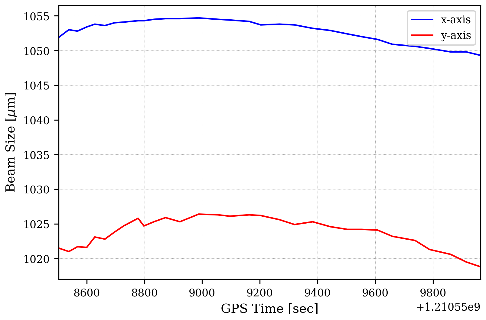
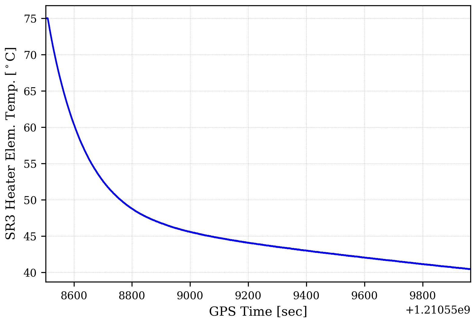
TVo, Dan, and Alexei are going to take some beam scans of the main beam today and tomorrow morning as part of the diagnostic of the astigmatism problem we think we have, but we're likely ready for the HAM6 north door to go back on tomorrow or Friday. We'll decide at the morning meeting tomorrow.