Derek Davis, Laurel White, Miriam Cabero
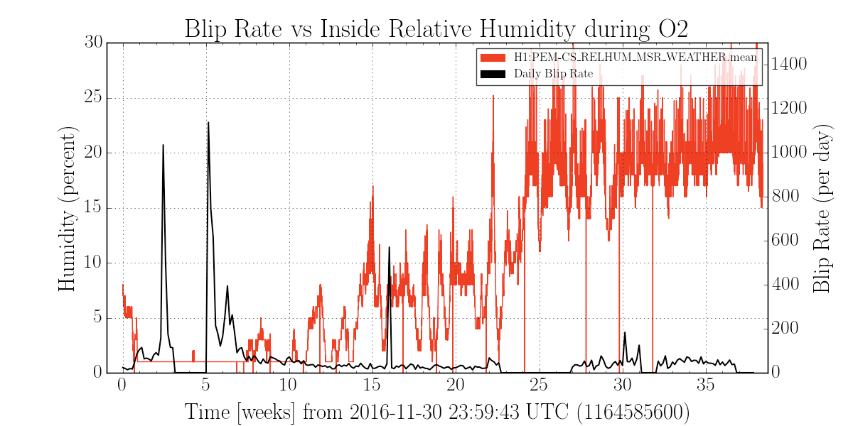
Following up a study done in O1 (see alog 28534) connecting internal humidity rates to an increase in the number of blips glitches, we repeated this analysis for O2. A plot of the blip glitch rate (based on Gravity Spy classifications) and relative humidity inside the CS mass storage room is attached.
The highest blip rates for the run in weeks 2-7 did correspond with a time of extremely low internal humidity, adding support to the previous theory that these trends are related. However, periods of similarly low humidity rates past week 7 did not correlate with elevated blip rates. Further follow up of how blip glitches during each of these low humidity periods (as was done in the previous study) may also help understand what is driving these large increases in blip glitch rate and whether efforts to better control the internal humidity are warranted.